2005 MERCEDES-BENZ SPRINTER clock
[x] Cancel search: clockPage 525 of 1232
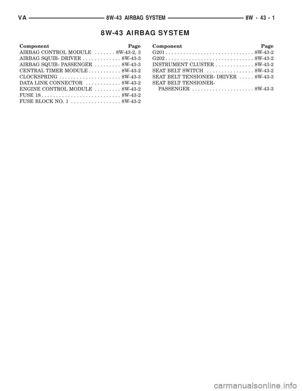
8W-43 AIRBAG SYSTEM
Component Page
AIRBAG CONTROL MODULE....... 8W-43-2, 3
AIRBAG SQUIB- DRIVER............. 8W-43-3
AIRBAG SQUIB- PASSENGER......... 8W-43-3
CENTRAL TIMER MODULE........... 8W-43-2
CLOCKSPRING..................... 8W-43-3
DATA LINK CONNECTOR............ 8W-43-2
ENGINE CONTROL MODULE......... 8W-43-2
FUSE 18........................... 8W-43-2
FUSE BLOCK NO. 1................. 8W-43-2Component Page
G201.............................. 8W-43-2
G202.............................. 8W-43-2
INSTRUMENT CLUSTER............. 8W-43-2
SEAT BELT SWITCH................ 8W-43-2
SEAT BELT TENSIONER- DRIVER..... 8W-43-3
SEAT BELT TENSIONER-
PASSENGER..................... 8W-43-3
VA8W-43 AIRBAG SYSTEM 8W - 43 - 1
Page 627 of 1232
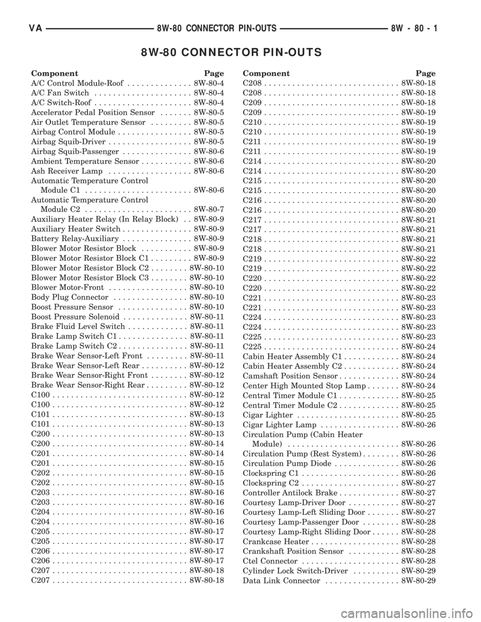
8W-80 CONNECTOR PIN-OUTS
Component Page
A/C Control Module-Roof.............. 8W-80-4
A/C Fan Switch..................... 8W-80-4
A/C Switch-Roof..................... 8W-80-4
Accelerator Pedal Position Sensor....... 8W-80-5
Air Outlet Temperature Sensor......... 8W-80-5
Airbag Control Module................ 8W-80-5
Airbag Squib-Driver.................. 8W-80-5
Airbag Squib-Passenger............... 8W-80-6
Ambient Temperature Sensor........... 8W-80-6
Ash Receiver Lamp.................. 8W-80-6
Automatic Temperature Control
Module C1....................... 8W-80-6
Automatic Temperature Control
Module C2....................... 8W-80-7
Auxiliary Heater Relay (In Relay Block) . . 8W-80-9
Auxiliary Heater Switch............... 8W-80-9
Battery Relay-Auxiliary............... 8W-80-9
Blower Motor Resistor Block........... 8W-80-9
Blower Motor Resistor Block C1......... 8W-80-9
Blower Motor Resistor Block C2........ 8W-80-10
Blower Motor Resistor Block C3........ 8W-80-10
Blower Motor-Front................. 8W-80-10
Body Plug Connector................ 8W-80-10
Boost Pressure Sensor............... 8W-80-10
Boost Pressure Solenoid.............. 8W-80-11
Brake Fluid Level Switch............. 8W-80-11
Brake Lamp Switch C1............... 8W-80-11
Brake Lamp Switch C2............... 8W-80-11
Brake Wear Sensor-Left Front......... 8W-80-11
Brake Wear Sensor-Left Rear.......... 8W-80-12
Brake Wear Sensor-Right Front........ 8W-80-12
Brake Wear Sensor-Right Rear......... 8W-80-12
C100............................. 8W-80-12
C100............................. 8W-80-12
C101............................. 8W-80-13
C101............................. 8W-80-13
C200............................. 8W-80-13
C200............................. 8W-80-14
C201............................. 8W-80-14
C201............................. 8W-80-15
C202............................. 8W-80-15
C202............................. 8W-80-15
C203............................. 8W-80-16
C203............................. 8W-80-16
C204............................. 8W-80-16
C204............................. 8W-80-16
C205............................. 8W-80-17
C205............................. 8W-80-17
C206............................. 8W-80-17
C206............................. 8W-80-17
C207............................. 8W-80-18
C207............................. 8W-80-18Component Page
C208............................. 8W-80-18
C208............................. 8W-80-18
C209............................. 8W-80-18
C209............................. 8W-80-19
C210............................. 8W-80-19
C210............................. 8W-80-19
C211 ............................. 8W-80-19
C211 ............................. 8W-80-19
C214............................. 8W-80-20
C214............................. 8W-80-20
C215............................. 8W-80-20
C215............................. 8W-80-20
C216............................. 8W-80-20
C216............................. 8W-80-20
C217............................. 8W-80-21
C217............................. 8W-80-21
C218............................. 8W-80-21
C218............................. 8W-80-21
C219............................. 8W-80-22
C219............................. 8W-80-22
C220............................. 8W-80-22
C220............................. 8W-80-22
C221............................. 8W-80-23
C221............................. 8W-80-23
C224............................. 8W-80-23
C224............................. 8W-80-23
C225............................. 8W-80-23
C225............................. 8W-80-24
Cabin Heater Assembly C1............ 8W-80-24
Cabin Heater Assembly C2............ 8W-80-24
Camshaft Position Sensor............. 8W-80-24
Center High Mounted Stop Lamp....... 8W-80-24
Central Timer Module C1............. 8W-80-25
Central Timer Module C2............. 8W-80-25
Cigar Lighter...................... 8W-80-25
Cigar Lighter Lamp................. 8W-80-26
Circulation Pump (Cabin Heater
Module)........................ 8W-80-26
Circulation Pump (Rest System)........ 8W-80-26
Circulation Pump Diode.............. 8W-80-26
Clockspring C1..................... 8W-80-26
Clockspring C2..................... 8W-80-27
Controller Antilock Brake............. 8W-80-27
Courtesy Lamp-Driver Door........... 8W-80-27
Courtesy Lamp-Left Sliding Door....... 8W-80-27
Courtesy Lamp-Passenger Door........ 8W-80-28
Courtesy Lamp-Right Sliding Door...... 8W-80-28
Crankcase Heater................... 8W-80-28
Crankshaft Position Sensor........... 8W-80-28
Ctel Connector..................... 8W-80-28
Cylinder Lock Switch-Driver.......... 8W-80-29
Data Link Connector................ 8W-80-29
VA8W-80 CONNECTOR PIN-OUTS 8W - 80 - 1
Page 652 of 1232
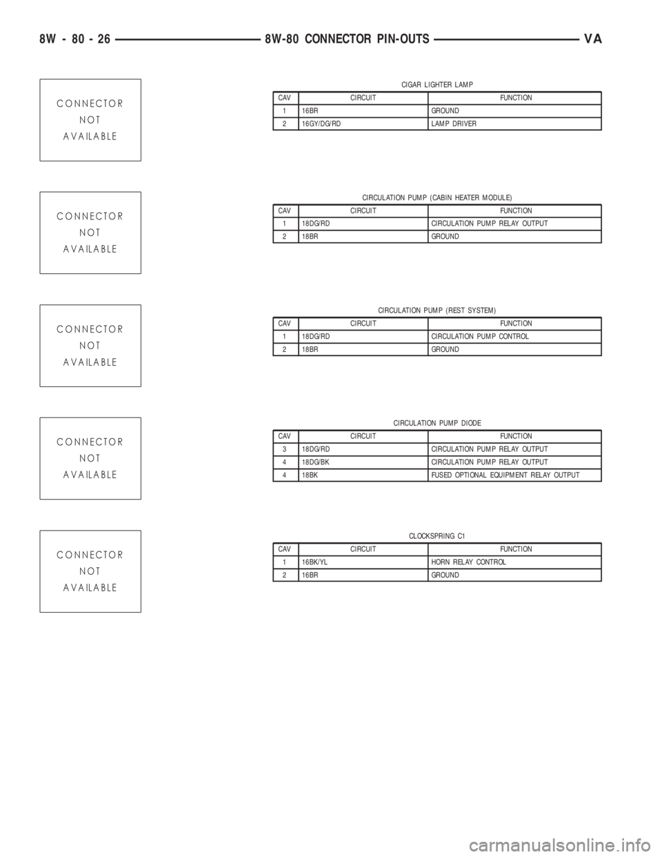
CIGAR LIGHTER LAMP
CAV CIRCUIT FUNCTION
1 16BR GROUND
2 16GY/DG/RD LAMP DRIVER
CIRCULATION PUMP (CABIN HEATER MODULE)
CAV CIRCUIT FUNCTION
1 18DG/RD CIRCULATION PUMP RELAY OUTPUT
2 18BR GROUND
CIRCULATION PUMP (REST SYSTEM)
CAV CIRCUIT FUNCTION
1 18DG/RD CIRCULATION PUMP CONTROL
2 18BR GROUND
CIRCULATION PUMP DIODE
CAV CIRCUIT FUNCTION
3 18DG/RD CIRCULATION PUMP RELAY OUTPUT
4 18DG/BK CIRCULATION PUMP RELAY OUTPUT
4 18BK FUSED OPTIONAL EQUIPMENT RELAY OUTPUT
CLOCKSPRING C1
CAV CIRCUIT FUNCTION
1 16BK/YL HORN RELAY CONTROL
2 16BR GROUND
8W - 80 - 26 8W-80 CONNECTOR PIN-OUTSVA
Page 653 of 1232
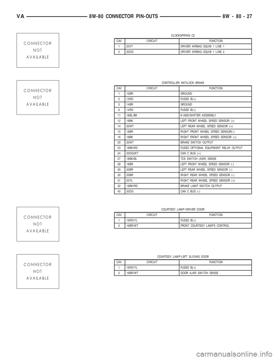
CLOCKSPRING C2
CAV CIRCUIT FUNCTION
1 20VT DRIVER AIRBAG SQUIB 1 LINE 1
2 20DG DRIVER AIRBAG SQUIB 1 LINE 2
CONTROLLER ANTILOCK BRAKE
CAV CIRCUIT FUNCTION
1 12BR GROUND
2 12RD FUSED B(+)
5 14BR GROUND
6 14RD FUSED B(+)
11 18BL/BK K-ABS/SHIFTER ASSEMBLY
12 18BK LEFT FRONT WHEEL SPEED SENSOR (+)
14 20WT LEFT REAR WHEEL SPEED SENSOR (+)
15 18BR RIGHT FRONT WHEEL SPEED SENSOR(-)
16 18BK RIGHT FRONT WHEEL SPEED SENSOR (+)
20 20WT BRAKE SWITCH OUTPUT
23 18BK/RD FUSED OPTIONAL EQUIPMENT RELAY OUTPUT
24 20DG/WT CAN C BUS (+)
27 18BK/BL TCS SWITCH (ASR) SENSE
28 18BR LEFT FRONT WHEEL SPEED SENSOR (-)
29 20BR LEFT REAR WHEEL SPEED SENSOR (-)
30 20BR RIGHT REAR WHEEL SPEED SENSOR (-)
31 20YL RIGHT REAR WHEEL SPEED SENSOR (+)
32 18BK/RD BRAKE LAMP SWITCH OUTPUT
40 20DG CAN C BUS (-)
COURTESY LAMP-DRIVER DOOR
CAV CIRCUIT FUNCTION
1 16RD/YL FUSED B(+)
2 16BR/WT FRONT COURTESY LAMPS CONTROL
COURTESY LAMP-LEFT SLIDING DOOR
CAV CIRCUIT FUNCTION
1 16RD/YL FUSED B(+)
2 16BR/WT DOOR AJAR SWITCH SENSE
VA8W-80 CONNECTOR PIN-OUTS 8W - 80 - 27
Page 697 of 1232
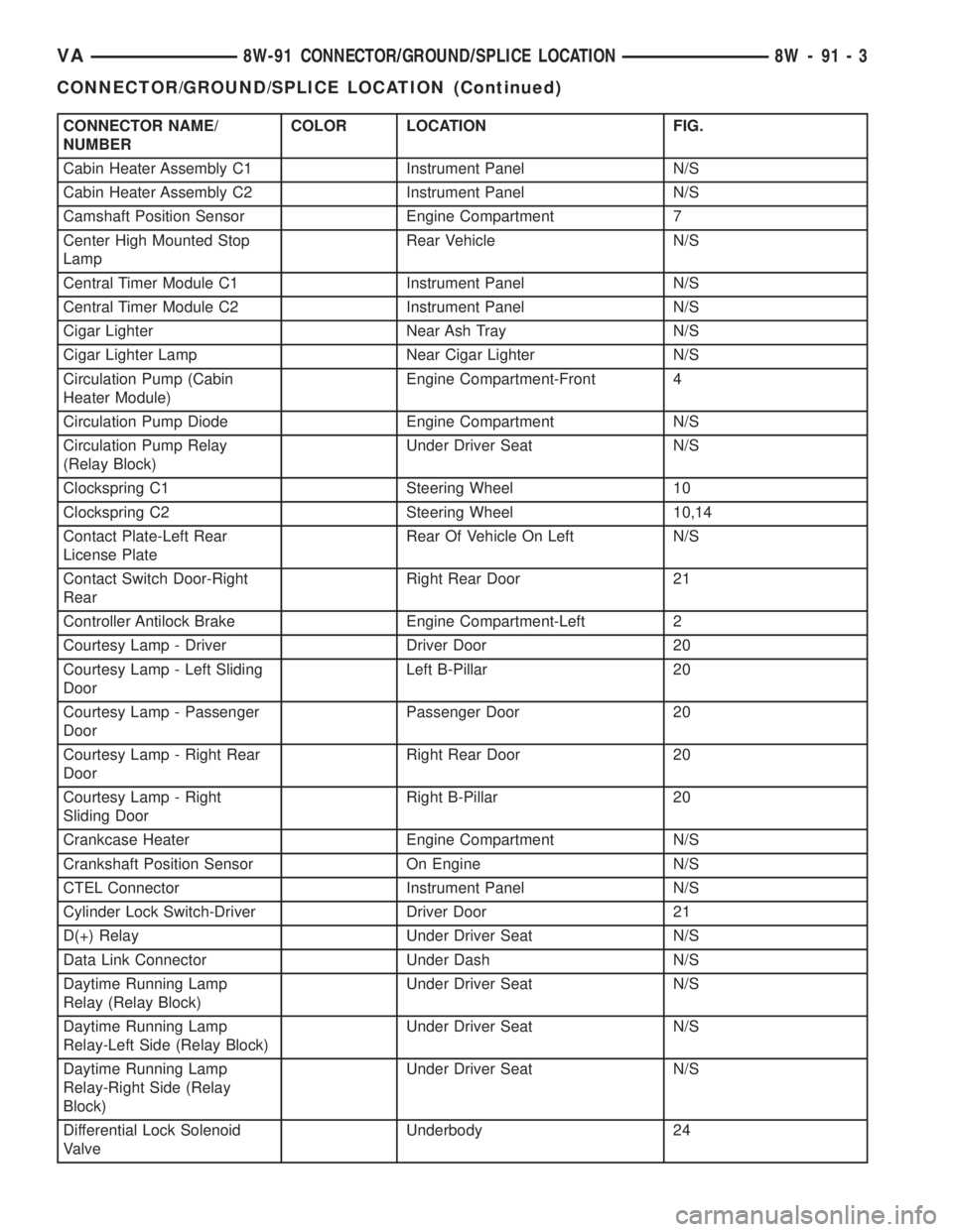
CONNECTOR NAME/
NUMBERCOLOR LOCATION FIG.
Cabin Heater Assembly C1 Instrument Panel N/S
Cabin Heater Assembly C2 Instrument Panel N/S
Camshaft Position Sensor Engine Compartment 7
Center High Mounted Stop
LampRear Vehicle N/S
Central Timer Module C1 Instrument Panel N/S
Central Timer Module C2 Instrument Panel N/S
Cigar Lighter Near Ash Tray N/S
Cigar Lighter Lamp Near Cigar Lighter N/S
Circulation Pump (Cabin
Heater Module)Engine Compartment-Front 4
Circulation Pump Diode Engine Compartment N/S
Circulation Pump Relay
(Relay Block)Under Driver Seat N/S
Clockspring C1 Steering Wheel 10
Clockspring C2 Steering Wheel 10,14
Contact Plate-Left Rear
License PlateRear Of Vehicle On Left N/S
Contact Switch Door-Right
RearRight Rear Door 21
Controller Antilock Brake Engine Compartment-Left 2
Courtesy Lamp - Driver Driver Door 20
Courtesy Lamp - Left Sliding
DoorLeft B-Pillar 20
Courtesy Lamp - Passenger
DoorPassenger Door 20
Courtesy Lamp - Right Rear
DoorRight Rear Door 20
Courtesy Lamp - Right
Sliding DoorRight B-Pillar 20
Crankcase Heater Engine Compartment N/S
Crankshaft Position Sensor On Engine N/S
CTEL Connector Instrument Panel N/S
Cylinder Lock Switch-Driver Driver Door 21
D(+) Relay Under Driver Seat N/S
Data Link Connector Under Dash N/S
Daytime Running Lamp
Relay (Relay Block)Under Driver Seat N/S
Daytime Running Lamp
Relay-Left Side (Relay Block)Under Driver Seat N/S
Daytime Running Lamp
Relay-Right Side (Relay
Block)Under Driver Seat N/S
Differential Lock Solenoid
ValveUnderbody 24
VA8W-91 CONNECTOR/GROUND/SPLICE LOCATION 8W - 91 - 3
CONNECTOR/GROUND/SPLICE LOCATION (Continued)
Page 741 of 1232
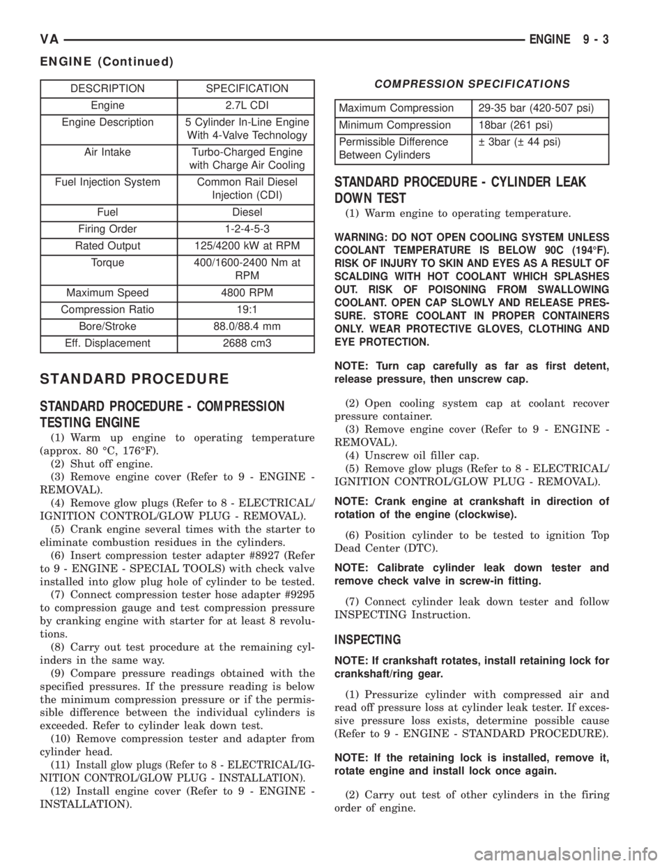
DESCRIPTION SPECIFICATION
Engine 2.7L CDI
Engine Description 5 Cylinder In-Line Engine
With 4-Valve Technology
Air Intake Turbo-Charged Engine
with Charge Air Cooling
Fuel Injection System Common Rail Diesel
Injection (CDI)
Fuel Diesel
Firing Order 1-2-4-5-3
Rated Output 125/4200 kW at RPM
Torque 400/1600-2400 Nm at
RPM
Maximum Speed 4800 RPM
Compression Ratio 19:1
Bore/Stroke 88.0/88.4 mm
Eff. Displacement 2688 cm3
STANDARD PROCEDURE
STANDARD PROCEDURE - COMPRESSION
TESTING ENGINE
(1) Warm up engine to operating temperature
(approx. 80 ÉC, 176ÉF).
(2) Shut off engine.
(3) Remove engine cover (Refer to 9 - ENGINE -
REMOVAL).
(4) Remove glow plugs (Refer to 8 - ELECTRICAL/
IGNITION CONTROL/GLOW PLUG - REMOVAL).
(5) Crank engine several times with the starter to
eliminate combustion residues in the cylinders.
(6) Insert compression tester adapter #8927 (Refer
to 9 - ENGINE - SPECIAL TOOLS) with check valve
installed into glow plug hole of cylinder to be tested.
(7) Connect compression tester hose adapter #9295
to compression gauge and test compression pressure
by cranking engine with starter for at least 8 revolu-
tions.
(8) Carry out test procedure at the remaining cyl-
inders in the same way.
(9) Compare pressure readings obtained with the
specified pressures. If the pressure reading is below
the minimum compression pressure or if the permis-
sible difference between the individual cylinders is
exceeded. Refer to cylinder leak down test.
(10) Remove compression tester and adapter from
cylinder head.
(11)
Install glow plugs (Refer to 8 - ELECTRICAL/IG-
NITION CONTROL/GLOW PLUG - INSTALLATION).
(12) Install engine cover (Refer to 9 - ENGINE -
INSTALLATION).
COMPRESSION SPECIFICATIONS
Maximum Compression 29-35 bar (420-507 psi)
Minimum Compression 18bar (261 psi)
Permissible Difference
Between Cylinders 3bar ( 44 psi)
STANDARD PROCEDURE - CYLINDER LEAK
DOWN TEST
(1) Warm engine to operating temperature.
WARNING: DO NOT OPEN COOLING SYSTEM UNLESS
COOLANT TEMPERATURE IS BELOW 90C (194ÉF).
RISK OF INJURY TO SKIN AND EYES AS A RESULT OF
SCALDING WITH HOT COOLANT WHICH SPLASHES
OUT. RISK OF POISONING FROM SWALLOWING
COOLANT. OPEN CAP SLOWLY AND RELEASE PRES-
SURE. STORE COOLANT IN PROPER CONTAINERS
ONLY. WEAR PROTECTIVE GLOVES, CLOTHING AND
EYE PROTECTION.
NOTE: Turn cap carefully as far as first detent,
release pressure, then unscrew cap.
(2) Open cooling system cap at coolant recover
pressure container.
(3) Remove engine cover (Refer to 9 - ENGINE -
REMOVAL).
(4) Unscrew oil filler cap.
(5) Remove glow plugs (Refer to 8 - ELECTRICAL/
IGNITION CONTROL/GLOW PLUG - REMOVAL).
NOTE: Crank engine at crankshaft in direction of
rotation of the engine (clockwise).
(6) Position cylinder to be tested to ignition Top
Dead Center (DTC).
NOTE: Calibrate cylinder leak down tester and
remove check valve in screw-in fitting.
(7) Connect cylinder leak down tester and follow
INSPECTING Instruction.
INSPECTING
NOTE: If crankshaft rotates, install retaining lock for
crankshaft/ring gear.
(1) Pressurize cylinder with compressed air and
read off pressure loss at cylinder leak tester. If exces-
sive pressure loss exists, determine possible cause
(Refer to 9 - ENGINE - STANDARD PROCEDURE).
NOTE: If the retaining lock is installed, remove it,
rotate engine and install lock once again.
(2) Carry out test of other cylinders in the firing
order of engine.
VAENGINE 9 - 3
ENGINE (Continued)
Page 767 of 1232
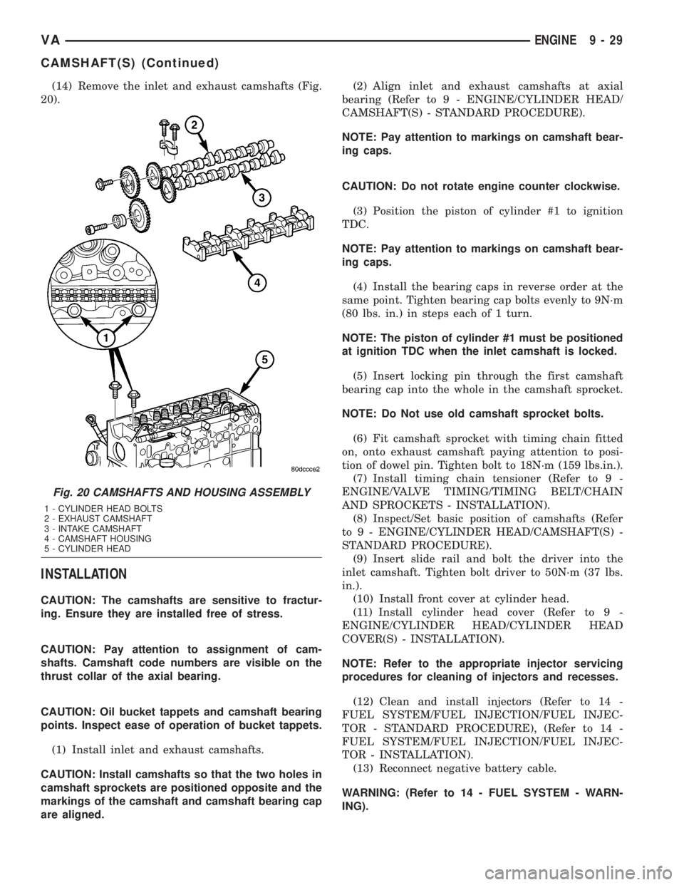
(14) Remove the inlet and exhaust camshafts (Fig.
20).
INSTALLATION
CAUTION: The camshafts are sensitive to fractur-
ing. Ensure they are installed free of stress.
CAUTION: Pay attention to assignment of cam-
shafts. Camshaft code numbers are visible on the
thrust collar of the axial bearing.
CAUTION: Oil bucket tappets and camshaft bearing
points. Inspect ease of operation of bucket tappets.
(1) Install inlet and exhaust camshafts.
CAUTION: Install camshafts so that the two holes in
camshaft sprockets are positioned opposite and the
markings of the camshaft and camshaft bearing cap
are aligned.(2) Align inlet and exhaust camshafts at axial
bearing (Refer to 9 - ENGINE/CYLINDER HEAD/
CAMSHAFT(S) - STANDARD PROCEDURE).
NOTE: Pay attention to markings on camshaft bear-
ing caps.
CAUTION: Do not rotate engine counter clockwise.
(3) Position the piston of cylinder #1 to ignition
TDC.
NOTE: Pay attention to markings on camshaft bear-
ing caps.
(4) Install the bearing caps in reverse order at the
same point. Tighten bearing cap bolts evenly to 9N´m
(80 lbs. in.) in steps each of 1 turn.
NOTE: The piston of cylinder #1 must be positioned
at ignition TDC when the inlet camshaft is locked.
(5) Insert locking pin through the first camshaft
bearing cap into the whole in the camshaft sprocket.
NOTE: Do Not use old camshaft sprocket bolts.
(6) Fit camshaft sprocket with timing chain fitted
on, onto exhaust camshaft paying attention to posi-
tion of dowel pin. Tighten bolt to 18N´m (159 lbs.in.).
(7) Install timing chain tensioner (Refer to 9 -
ENGINE/VALVE TIMING/TIMING BELT/CHAIN
AND SPROCKETS - INSTALLATION).
(8) Inspect/Set basic position of camshafts (Refer
to 9 - ENGINE/CYLINDER HEAD/CAMSHAFT(S) -
STANDARD PROCEDURE).
(9) Insert slide rail and bolt the driver into the
inlet camshaft. Tighten bolt driver to 50N´m (37 lbs.
in.).
(10) Install front cover at cylinder head.
(11) Install cylinder head cover (Refer to 9 -
ENGINE/CYLINDER HEAD/CYLINDER HEAD
COVER(S) - INSTALLATION).
NOTE: Refer to the appropriate injector servicing
procedures for cleaning of injectors and recesses.
(12) Clean and install injectors (Refer to 14 -
FUEL SYSTEM/FUEL INJECTION/FUEL INJEC-
TOR - STANDARD PROCEDURE), (Refer to 14 -
FUEL SYSTEM/FUEL INJECTION/FUEL INJEC-
TOR - INSTALLATION).
(13) Reconnect negative battery cable.
WARNING: (Refer to 14 - FUEL SYSTEM - WARN-
ING).
Fig. 20 CAMSHAFTS AND HOUSING ASSEMBLY
1 - CYLINDER HEAD BOLTS
2 - EXHAUST CAMSHAFT
3 - INTAKE CAMSHAFT
4 - CAMSHAFT HOUSING
5 - CYLINDER HEAD
VAENGINE 9 - 29
CAMSHAFT(S) (Continued)
Page 769 of 1232
(5) Connect the camshaft position sensor.
(6) Connect the return flow line.
(7) Attach oil separator hose.
(8) Install the fuel injector lines (Refer to 14 -
FUEL SYSTEM/FUEL DELIVERY/FUEL LINES -
INSTALLATION).
(9) Connect negative battery cable.
WARNING: (Refer to 14 - FUEL SYSTEM - WARN-
ING).
WARNING: USE EXTREME CAUTION WHEN ENGINE
IS OPERATING. DO NOT STAND IN A DIRECT LINE
WITH FAN. DO NOT PUT YOUR HANDS NEAR PUL-
LEYS, BELTS OR FAN. DO NOT WEAR LOOSE
CLOTHES.
(10) Start engine and inspect for leaks. Care must
be take to observe the fuel system warning (Refer to
14 - FUEL SYSTEM - WARNING).
VALVE SPRINGS
REMOVAL
REMOVAL - VALVE SPRINGS
(1) Disconnect negative battery cable.
(2) Remove glow plugs (Refer to 8 - ELECTRICAL/
IGNITION CONTROL/GLOW PLUG - REMOVAL).
(3) Remove injectors (Refer to 14 - FUEL SYS-
TEM/FUEL INJECTION/FUEL INJECTOR -
REMOVAL).
(4) Remove cylinder head cover (Refer to 9 -
ENGINE/CYLINDER HEAD/CYLINDER HEAD
COVER(S) - REMOVAL).
(5) Remove timing chain tensioner (Refer to 9 -
ENGINE/VALVE TIMING/TIMING BELT/CHAIN
AND SPROCKETS - REMOVAL).
(6) Remove front cover at cylinder head (Refer to 9
- ENGINE/CYLINDER HEAD - REMOVAL).
(7) Remove top guide rail (Refer to 9 - ENGINE/
CYLINDER HEAD - REMOVAL).
(8) Remove camshafts (Refer to 9 - ENGINE/CYL-
INDER HEAD/CAMSHAFT(S) - REMOVAL).
NOTE: The timing chain must be held in up position
so as not to jam during procedure.
(9) Position piston of cylinder to be processed to
DTC by rotating the crankshaft clockwise.DO NOT
crank engine.DO NOT rotate engine backward.
(10) Install crankshaft lock, special tool #8932.
(11) Seal injector hole with connection piece and
retain with orginal tensioning claw.(12) Connect cylinder leak tester with adaptors
and pressurize the cylinder to 5 bar (73 psi.).
WARNING: Valve springs and retainers must be
kept in order of the cylinder they were removed.
NOTE: Using valve service tools #9307, screw
retaining fork into threaded edge of cylinder head
and position thrust piece vertically at top of valve
spring retainer.
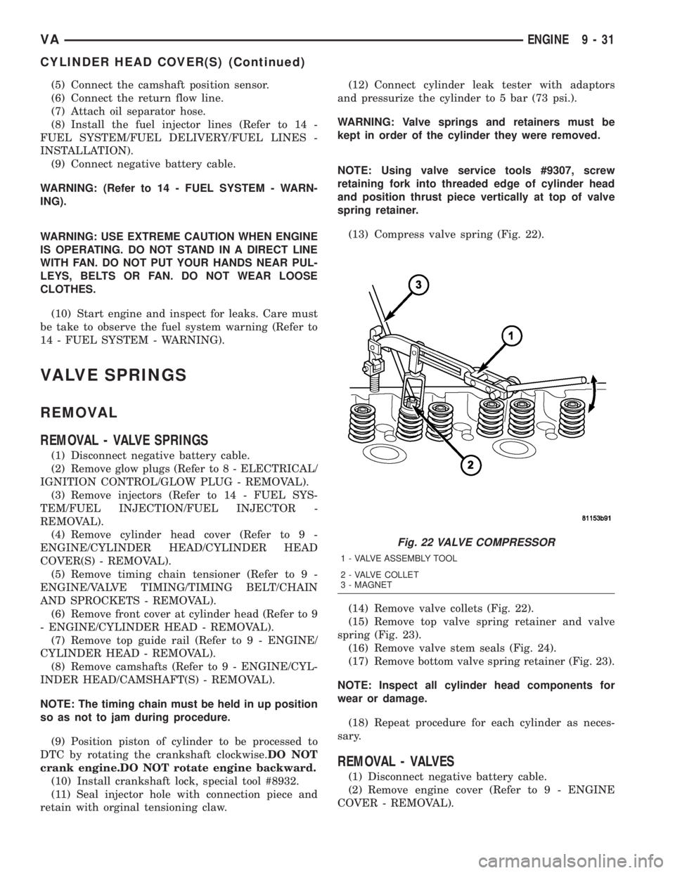
(13) Compress valve spring (Fig. 22).
(14) Remove valve collets (Fig. 22).
(15) Remove top valve spring retainer and valve
spring (Fig. 23).
(16) Remove valve stem seals (Fig. 24).
(17) Remove bottom valve spring retainer (Fig. 23).
NOTE: Inspect all cylinder head components for
wear or damage.
(18) Repeat procedure for each cylinder as neces-
sary.
REMOVAL - VALVES
(1) Disconnect negative battery cable.
(2) Remove engine cover (Refer to 9 - ENGINE
COVER - REMOVAL).
Fig. 22 VALVE COMPRESSOR
1 - VALVE ASSEMBLY TOOL
2 - VALVE COLLET
3 - MAGNET
VAENGINE 9 - 31
CYLINDER HEAD COVER(S) (Continued)