2005 MERCEDES-BENZ SPRINTER clock
[x] Cancel search: clockPage 770 of 1232
(3) Remove cylinder head (Refer to 9 - ENGINE/
CYLINDER HEAD - REMOVAL).WARNING: Suitably mark the valve and the position
in the cylinder head before removal. Failure to do
so will result in improperly seated valves and pos-
sible engine damage after reassembly.
NOTE: Using tool, screw retaining fork into
threaded edge of cylinder head and position thrust
piece vertically at top of valve spring retainer.
(4) Using a suitable valve spring compressor, com-
press valve spring.
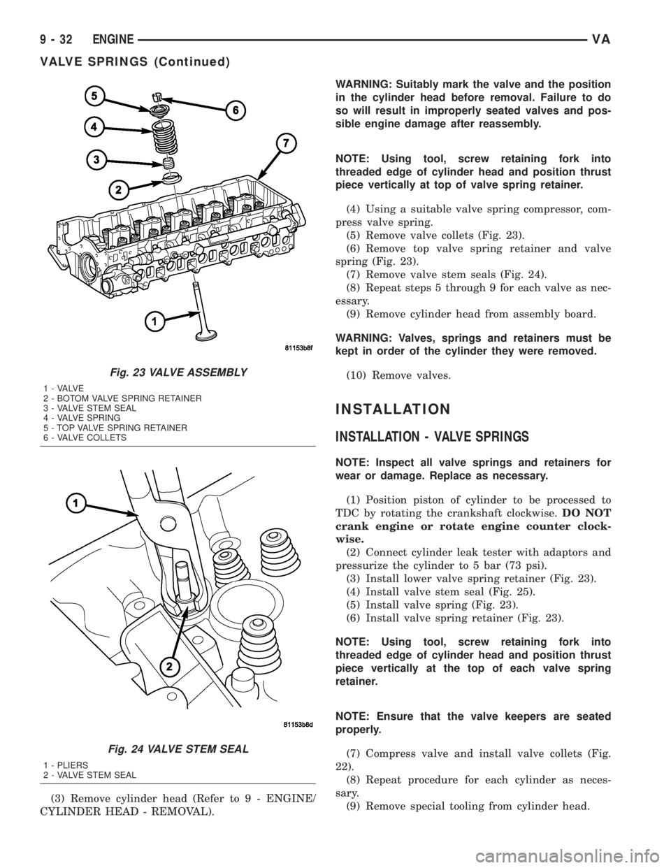
(5) Remove valve collets (Fig. 23).
(6) Remove top valve spring retainer and valve
spring (Fig. 23).
(7) Remove valve stem seals (Fig. 24).
(8) Repeat steps 5 through 9 for each valve as nec-
essary.
(9) Remove cylinder head from assembly board.
WARNING: Valves, springs and retainers must be
kept in order of the cylinder they were removed.
(10) Remove valves.
INSTALLATION
INSTALLATION - VALVE SPRINGS
NOTE: Inspect all valve springs and retainers for
wear or damage. Replace as necessary.
(1) Position piston of cylinder to be processed to
TDC by rotating the crankshaft clockwise.DO NOT
crank engine or rotate engine counter clock-
wise.
(2) Connect cylinder leak tester with adaptors and
pressurize the cylinder to 5 bar (73 psi).
(3) Install lower valve spring retainer (Fig. 23).
(4) Install valve stem seal (Fig. 25).
(5) Install valve spring (Fig. 23).
(6) Install valve spring retainer (Fig. 23).
NOTE: Using tool, screw retaining fork into
threaded edge of cylinder head and position thrust
piece vertically at the top of each valve spring
retainer.
NOTE: Ensure that the valve keepers are seated
properly.
(7) Compress valve and install valve collets (Fig.
22).
(8) Repeat procedure for each cylinder as neces-
sary.
(9) Remove special tooling from cylinder head.
Fig. 23 VALVE ASSEMBLY
1 - VALVE
2 - BOTOM VALVE SPRING RETAINER
3 - VALVE STEM SEAL
4 - VALVE SPRING
5 - TOP VALVE SPRING RETAINER
6 - VALVE COLLETS
Fig. 24 VALVE STEM SEAL
1 - PLIERS
2 - VALVE STEM SEAL
9 - 32 ENGINEVA
VALVE SPRINGS (Continued)
Page 792 of 1232
(6) Remove pressed - out oil pump chain pin from
chain seperation tool.
CAUTION: IT IS ESSENTIAL that the installation pro-
cedure for the oil pump chain is followed exactly.
Failure to do so will result in severe engine dam-
age.
INSTALLATION
INSTALLATION
NOTE: If the oil pump is dry, fill it with clean engine
oil before installation. Clean the oil pick±up tube
and strainer.
(1) Clean all sealing surfaces.
(2) Position the oil pump onto the drive chain and
reset tensioner.
(3) Install oil pump retaining bolts and tighten to
18 N´m (160 lbs. in.).
(4) Install the oil pan (Refer to 9 - ENGINE/LU-
BRICATION/OIL PUMP - INSTALLATION).
(5) Refill the crankcase to the appropriate level
with the proper engine oil (see owners manual).
WARNING: USE EXTREME CAUTION WHEN THE
ENGINE IS OPERATING. DO NOT PUT YOURHANDS NEAR THE PULLEYS, BELTS OR FAN. DO
NOT WEAR LOOSE CLOTHES.
(6) Start the vehicle and inspect for leaks.
INSTALLATION - OIL PUMP CHAIN
CAUTION: IT IS ESSENTIAL that the installation pro-
cedure is followed exactly. Failure to do so will
result in severe engine damage.
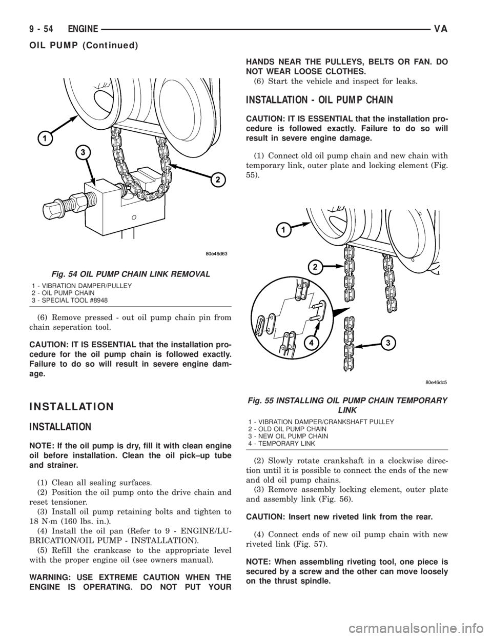
(1) Connect old oil pump chain and new chain with
temporary link, outer plate and locking element (Fig.
55).
(2) Slowly rotate crankshaft in a clockwise direc-
tion until it is possible to connect the ends of the new
and old oil pump chains.
(3) Remove assembly locking element, outer plate
and assembly link (Fig. 56).
CAUTION: Insert new riveted link from the rear.
(4) Connect ends of new oil pump chain with new
riveted link (Fig. 57).
NOTE: When assembling riveting tool, one piece is
secured by a screw and the other can move loosely
on the thrust spindle.
Fig. 54 OIL PUMP CHAIN LINK REMOVAL
1 - VIBRATION DAMPER/PULLEY
2 - OIL PUMP CHAIN
3 - SPECIAL TOOL #8948
Fig. 55 INSTALLING OIL PUMP CHAIN TEMPORARY
LINK
1 - VIBRATION DAMPER/CRANKSHAFT PULLEY
2 - OLD OIL PUMP CHAIN
3 - NEW OIL PUMP CHAIN
4 - TEMPORARY LINK
9 - 54 ENGINEVA
OIL PUMP (Continued)
Page 808 of 1232
(24) Remove camshaft sprocket to timing chain tie
straps.
(25) Install guide rail and tighten low pressure
fuel pump drive to 50N´m (37 lbs. ft.).
(26) Install low pressure fuel pump (Refer to 14 -
FUEL SYSTEM/FUEL DELIVERY/FUEL INJEC-
TION PUMP - INSTALLATION).
(27) Install timing chain tensioner (Refer to 9 -
ENGINE/VALVE TIMING/TIMING BELT/CHAIN
AND SPROCKETS - INSTALLATION).
(28) Install vacuum pump (Refer to 9 - ENGINE/
ENGINE BLOCK/INTERNAL VACUUM PUMP -
INSTALLATION).
(29) Install cylinder head cover (Refer to 9 -
ENGINE/CYLINDER HEAD/CYLINDER HEAD
COVER(S) - INSTALLATION).
(30) Install engine cover (Refer to 9 - ENGINE -
INSTALLATION).
(31) Connect negative battery cable.
WARNING: USE EXTREME CAUTION WHEN THE
ENGINE IS OPERATING. DO NOT PUT YOUR
HANDS NEAR THE PULLEYS BELTS OR FAN. DO
NOT WEAR LOOSE CLOTHES.
(32) Start engine and inspect for leaks. Care must
be taken to observe the fuel system warning (Refer to
14 - FUEL SYSTEM - WARNING).
TIMING CHAIN TENSIONER
REMOVAL
(1) Disconnect negative battery cable.
CAUTION: Rotate engine at crankshaft only. DO
NOT rotate the engine with the bolt of the camshaft
sprocket. DO NOT rotate the engine counter clock-
wise.
NOTE: Markings on the camshaft and camshaft
bearing cap must be aligned.
(2) Position piston of number 1 cylinder to ignition
TDC.
(3) Remove intake air scoop.
(4) Remove accessory drive belt and idler pulley
above generator (Refer to 7 - COOLING/ACCES-
SORY DRIVE/DRIVE BELTS - REMOVAL).
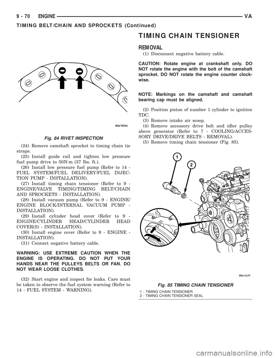
(5) Remove timing chain tensioner (Fig. 85).
Fig. 84 RIVET INSPECTION
Fig. 85 TIMING CHAIN TENSIONER
1 - TIMING CHAIN TENSIONER
2 - TIMING CHAIN TENSIONER SEAL
9 - 70 ENGINEVA
TIMING BELT/CHAIN AND SPROCKETS (Continued)
Page 865 of 1232
COLUMN
TABLE OF CONTENTS
page page
COLUMN
SPECIFICATIONS - TORQUE CHART.........5
INTERMEDIATE SHAFT
REMOVAL.............................5
INSTALLATION..........................5
KEY/LOCK CYLINDER
REMOVAL.............................6INSTALLATION..........................7
STEERING WHEEL
REMOVAL.............................7
INSTALLATION..........................7
COLUMN
SPECIFICATIONS - TORQUE CHART
TORQUE SPECIFICATIONS
DESCRIPTION N´m Ft. Lbs. In. Lbs.
Steering Wheel With
Airbag To Steering Shaft80 59 Ð
Jacket Tube For Steering
Shaft To Waist Rail25 18 221
U-Joint To Steering Gear
Shaft24 18 212
INTERMEDIATE SHAFT
REMOVAL
(1) Disconnect the ground cable from the battery.
(2) Remove the air bag module from the steering
wheel.
(3) Turn the steering wheel and lock the steering
wheel in the straight ahead position.The position
of the steering gear must not be altered again
for the entire duration of the work procedure.
(4) Remove the electrical center.
(5) Remove the steering wheel bolt.
(6) Remove the steering wheel from the steering
column.
(7) Remove the clockspring.Unscrew the retain-
ing bolts just enough to be able to remove the
clockspring. Do not twist or disassemble the
clockspring.
(8) Remove the combination switch.
(9) Disconnect the electrical connector for the igni-
tion lock.(10) Remove the spring for the brake pedal from
the steering column.
(11) Remove the fitted bolt from the universal joint
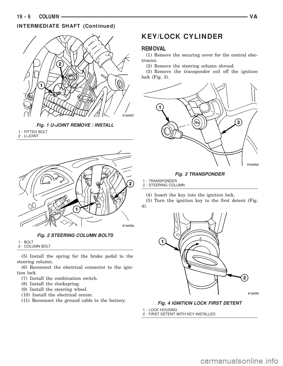
(Fig. 1).
(12) Remove the bolts in the steering column
bracket (Fig. 2).
(13) Remove the steering shaft with the universal
joint off the steering gear drive shaft (Fig. 1).
(14) Pull the steering shaft out of the rubber grom-
met in the cab floor.
INSTALLATION
(1) Install the steering shaft through the rubber
grommet in the cab floor.Ensure that the rubber
grommet is properly seated.
(2) Install the steering shaft with the universal
joint onto the steering gear shaft (Fig. 1).
(3) Install the bolts in the steering column bracket
(Fig. 2). Tighten to 24 N´m (18 ft. lbs.).
(4) Install the universal joint on the steering gear
shaft (Fig. 1). Tighten to 24 N´m (18 ft. lbs.).
VACOLUMN 19 - 5
Page 866 of 1232
(5) Install the spring for the brake pedal to the
steering column.
(6) Reconnect the electrical connector to the igni-
tion lock.
(7) Install the combination switch.
(8) Install the clockspring.
(9) Install the steering wheel.
(10) Install the electrical center.
(11) Reconnect the ground cable to the battery.
KEY/LOCK CYLINDER
REMOVAL
(1) Remove the securing cover for the central elec-
tronics.
(2) Remove the steering column shroud.
(3) Remove the transponder coil off the ignition
lock (Fig. 3).
(4) Insert the key into the ignition lock.
(5) Turn the ignition key to the first detent (Fig.
4).
Fig. 1 U-JOINT REMOVE / INSTALL
1 - FITTED BOLT
2 - U-JOINT
Fig. 2 STEERING COLUMN BOLTS
1 - BOLT
2 - COLUMN BOLT
Fig. 3 TRANSPONDER
1 - TRANSPONDER
2 - STEERING COLUMN
Fig. 4 IGNITION LOCK FIRST DETENT
1 - LOCK HOUSING
2 - FIRST DETENT WITH KEY INSTALLED
19 - 6 COLUMNVA
INTERMEDIATE SHAFT (Continued)
Page 904 of 1232
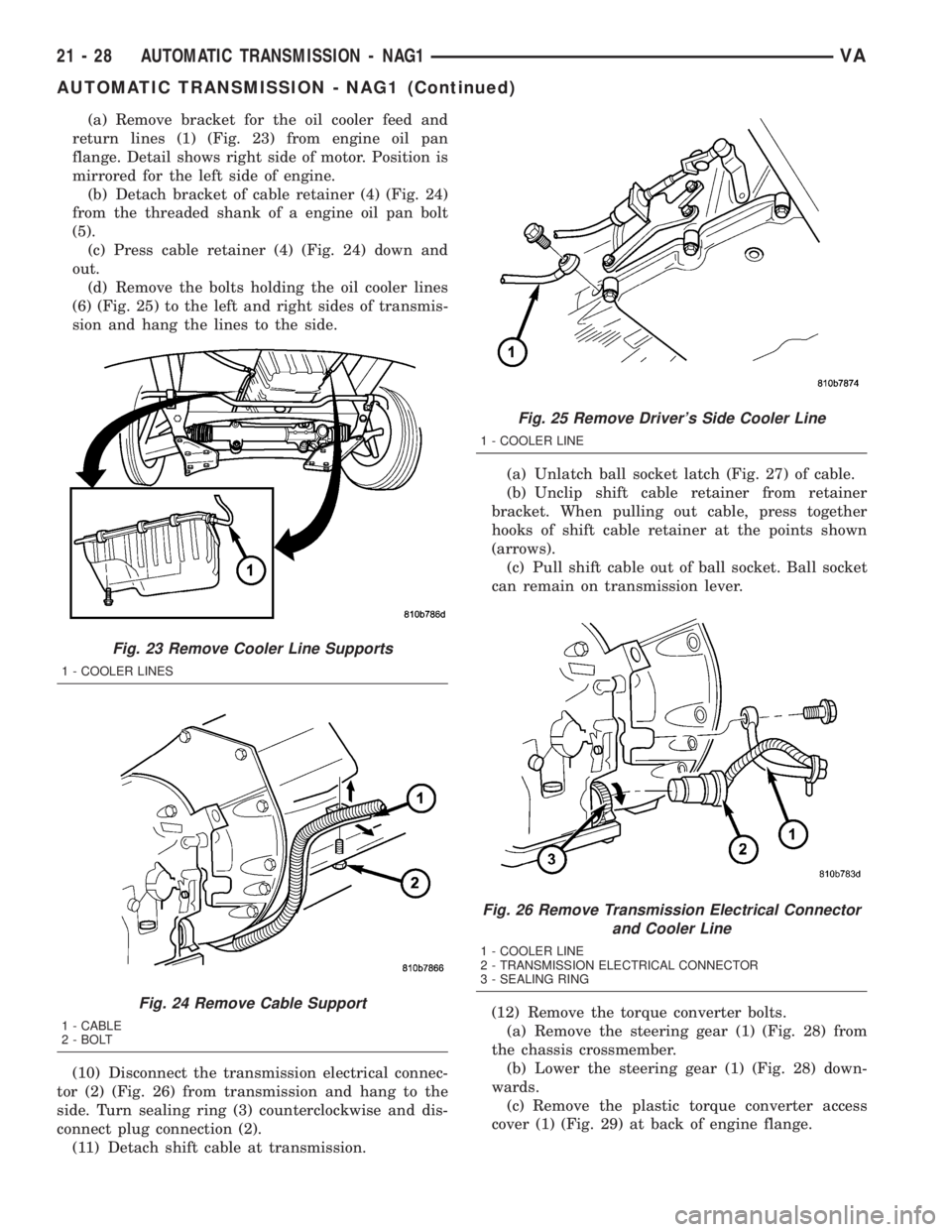
(a) Remove bracket for the oil cooler feed and
return lines (1) (Fig. 23) from engine oil pan
flange. Detail shows right side of motor. Position is
mirrored for the left side of engine.
(b) Detach bracket of cable retainer (4) (Fig. 24)
from the threaded shank of a engine oil pan bolt
(5).
(c) Press cable retainer (4) (Fig. 24) down and
out.
(d) Remove the bolts holding the oil cooler lines
(6) (Fig. 25) to the left and right sides of transmis-
sion and hang the lines to the side.
(10) Disconnect the transmission electrical connec-
tor (2) (Fig. 26) from transmission and hang to the
side. Turn sealing ring (3) counterclockwise and dis-
connect plug connection (2).
(11) Detach shift cable at transmission.(a) Unlatch ball socket latch (Fig. 27) of cable.
(b) Unclip shift cable retainer from retainer
bracket. When pulling out cable, press together
hooks of shift cable retainer at the points shown
(arrows).
(c) Pull shift cable out of ball socket. Ball socket
can remain on transmission lever.
(12) Remove the torque converter bolts.
(a) Remove the steering gear (1) (Fig. 28) from
the chassis crossmember.
(b) Lower the steering gear (1) (Fig. 28) down-
wards.
(c) Remove the plastic torque converter access
cover (1) (Fig. 29) at back of engine flange.
Fig. 23 Remove Cooler Line Supports
1 - COOLER LINES
Fig. 24 Remove Cable Support
1 - CABLE
2 - BOLT
Fig. 25 Remove Driver's Side Cooler Line
1 - COOLER LINE
Fig. 26 Remove Transmission Electrical Connector
and Cooler Line
1 - COOLER LINE
2 - TRANSMISSION ELECTRICAL CONNECTOR
3 - SEALING RING
21 - 28 AUTOMATIC TRANSMISSION - NAG1VA
AUTOMATIC TRANSMISSION - NAG1 (Continued)
Page 920 of 1232
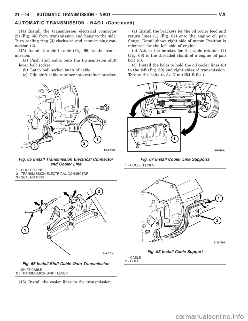
(14) Install the transmission electrical connector
(2) (Fig. 65) from transmission and hang to the side.
Turn sealing ring (3) clockwise and connect plug con-
nection (2).
(15) Install the shift cable (Fig. 66) to the trans-
mission.
(a) Push shift cable onto the transmission shift
lever ball socket.
(b) Latch ball socket latch of cable.
(c) Clip shift cable retainer into retainer bracket.
(16) Install the cooler lines to the transmission.(a) Install the brackets for the oil cooler feed and
return lines (1) (Fig. 67) onto the engine oil pan
flange. Detail shows right side of motor. Position is
mirrored for the left side of engine.
(b) Attach the bracket for the cable retainer (4)
(Fig. 68) to the threaded shank of a engine oil pan
bolt (5).
(c) Install the bolts to hold the oil cooler lines (6)
to the left (Fig. 69) and right sides of transmission.
Torque the bolts to 34 N´m (254 ft.lbs.).
Fig. 65 Install Transmission Electrical Connector
and Cooler Line
1 - COOLER LINE
2 - TRANSMISSION ELECTRICAL CONNECTOR
3 - SEALING RING
Fig. 66 Install Shift Cable Onto Transmission
1 - SHIFT CABLE
2 - TRANSMISSION SHIFT LEVER
Fig. 67 Install Cooler Line Supports
1 - COOLER LINES
Fig. 68 Install Cable Support
1 - CABLE
2 - BOLT
21 - 44 AUTOMATIC TRANSMISSION - NAG1VA
AUTOMATIC TRANSMISSION - NAG1 (Continued)
Page 968 of 1232
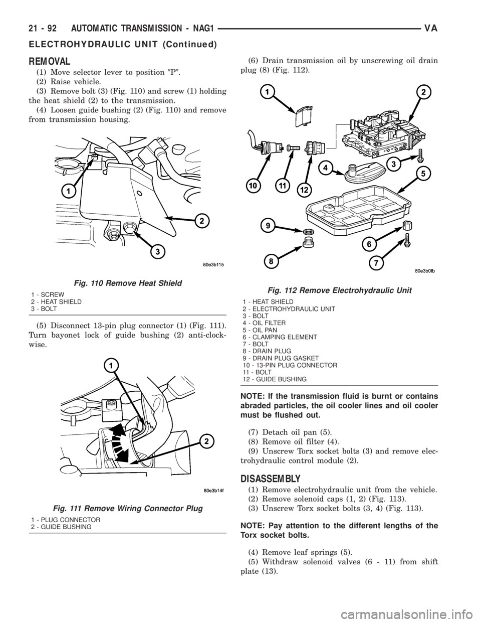
REMOVAL
(1) Move selector lever to position9P9.
(2) Raise vehicle.
(3) Remove bolt (3) (Fig. 110) and screw (1) holding
the heat shield (2) to the transmission.
(4) Loosen guide bushing (2) (Fig. 110) and remove
from transmission housing.
(5) Disconnect 13-pin plug connector (1) (Fig. 111).
Turn bayonet lock of guide bushing (2) anti-clock-
wise.(6) Drain transmission oil by unscrewing oil drain
plug (8) (Fig. 112).
NOTE: If the transmission fluid is burnt or contains
abraded particles, the oil cooler lines and oil cooler
must be flushed out.
(7) Detach oil pan (5).
(8) Remove oil filter (4).
(9) Unscrew Torx socket bolts (3) and remove elec-
trohydraulic control module (2).
DISASSEMBLY
(1) Remove electrohydraulic unit from the vehicle.
(2) Remove solenoid caps (1, 2) (Fig. 113).
(3) Unscrew Torx socket bolts (3, 4) (Fig. 113).
NOTE: Pay attention to the different lengths of the
Torx socket bolts.
(4) Remove leaf springs (5).
(5) Withdraw solenoid valves (6 - 11) from shift
plate (13).
Fig. 110 Remove Heat Shield
1 - SCREW
2 - HEAT SHIELD
3 - BOLT
Fig. 111 Remove Wiring Connector Plug
1 - PLUG CONNECTOR
2 - GUIDE BUSHING
Fig. 112 Remove Electrohydraulic Unit
1 - HEAT SHIELD
2 - ELECTROHYDRAULIC UNIT
3 - BOLT
4 - OIL FILTER
5 - OIL PAN
6 - CLAMPING ELEMENT
7 - BOLT
8 - DRAIN PLUG
9 - DRAIN PLUG GASKET
10 - 13-PIN PLUG CONNECTOR
11 - BOLT
12 - GUIDE BUSHING
21 - 92 AUTOMATIC TRANSMISSION - NAG1VA
ELECTROHYDRAULIC UNIT (Continued)