2005 MERCEDES-BENZ SPRINTER clock
[x] Cancel search: clockPage 252 of 1232
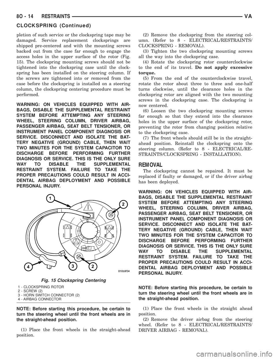
pletion of such service or the clockspring tape may be
damaged. Service replacement clocksprings are
shipped pre-centered and with the mounting screws
backed out from the case far enough to engage the
access holes in the upper surface of the rotor (Fig.
15). The clockspring mounting screws should not be
tightened into the clockspring case until the clock-
spring has been installed on the steering column. If
the screws are tightened into or removed from the
case before the clockspring is installed on a steering
column, the clockspring centering procedure must be
performed.
WARNING: ON VEHICLES EQUIPPED WITH AIR-
BAGS, DISABLE THE SUPPLEMENTAL RESTRAINT
SYSTEM BEFORE ATTEMPTING ANY STEERING
WHEEL, STEERING COLUMN, DRIVER AIRBAG,
PASSENGER AIRBAG, SEAT BELT TENSIONER, OR
INSTRUMENT PANEL COMPONENT DIAGNOSIS OR
SERVICE. DISCONNECT AND ISOLATE THE BAT-
TERY NEGATIVE (GROUND) CABLE, THEN WAIT
TWO MINUTES FOR THE SYSTEM CAPACITOR TO
DISCHARGE BEFORE PERFORMING FURTHER
DIAGNOSIS OR SERVICE. THIS IS THE ONLY SURE
WAY TO DISABLE THE SUPPLEMENTAL
RESTRAINT SYSTEM. FAILURE TO TAKE THE
PROPER PRECAUTIONS COULD RESULT IN ACCI-
DENTAL AIRBAG DEPLOYMENT AND POSSIBLE
PERSONAL INJURY.
NOTE: Before starting this procedure, be certain to
turn the steering wheel until the front wheels are in
the straight-ahead position.
(1) Place the front wheels in the straight-ahead
position.(2) Remove the clockspring from the steering col-
umn. (Refer to 8 - ELECTRICAL/RESTRAINTS/
CLOCKSPRING - REMOVAL).
(3) Tighten the two clockspring mounting screws
all the way into the clockspring case.
(4) Rotate the clockspring rotor counterclockwise
to the end of its travel.Do not apply excessive
torque.
(5) From the end of the counterclockwise travel,
rotate the rotor about three to three and one-half
turns clockwise, until the clearance holes in the
clockspring rotor are aligned with the two mounting
screws in the clockspring case. The clockspring is
now centered.
(6) Loosen the two clockspring mounting screws
far enough so that they extend into the clearance
holes in the upper surface of the clockspring rotor,
preventing the rotor from changing position relative
to the clockspring case.
(7) The front wheels should still be in the straight-
ahead position. Reinstall the clockspring onto the
steering column. (Refer to 8 - ELECTRICAL/RE-
STRAINTS/CLOCKSPRING - INSTALLATION).
REMOVAL
The clockspring cannot be repaired. It must be
replaced if faulty or damaged, or if the driver airbag
has been deployed.
WARNING: ON VEHICLES EQUIPPED WITH AIR-
BAGS, DISABLE THE SUPPLEMENTAL RESTRAINT
SYSTEM BEFORE ATTEMPTING ANY STEERING
WHEEL, STEERING COLUMN, DRIVER AIRBAG,
PASSENGER AIRBAG, SEAT BELT TENSIONER, OR
INSTRUMENT PANEL COMPONENT DIAGNOSIS OR
SERVICE. DISCONNECT AND ISOLATE THE BAT-
TERY NEGATIVE (GROUND) CABLE, THEN WAIT
TWO MINUTES FOR THE SYSTEM CAPACITOR TO
DISCHARGE BEFORE PERFORMING FURTHER
DIAGNOSIS OR SERVICE. THIS IS THE ONLY SURE
WAY TO DISABLE THE SUPPLEMENTAL
RESTRAINT SYSTEM. FAILURE TO TAKE THE
PROPER PRECAUTIONS COULD RESULT IN ACCI-
DENTAL AIRBAG DEPLOYMENT AND POSSIBLE
PERSONAL INJURY.
NOTE: Before starting this procedure, be certain to
turn the steering wheel until the front wheels are in
the straight-ahead position.
(1) Place the front wheels in the straight ahead
position.
(2) Remove the driver airbag from the steering
wheel. (Refer to 8 - ELECTRICAL/RESTRAINTS/
DRIVER AIRBAG - REMOVAL).
Fig. 15 Clockspring Centering
1 - CLOCKSPRING ROTOR
2 - SCREW (2)
3 - HORN SWITCH CONNECTOR (2)
4 - AIRBAG CONNECTOR
8O - 14 RESTRAINTSVA
CLOCKSPRING (Continued)
Page 253 of 1232
(3) Disconnect the clockspring upper pigtail wire
connectors from the terminals of the horn switch
located in the hub cavity of the steering wheel.
(4) Remove the steering wheel from the steering
column. (Refer to 19 - STEERING/COLUMN/STEER-
ING WHEEL - REMOVAL).
(5) Remove the steering column opening cover
from the instrument panel. (Refer to 23 - BODY/IN-
STRUMENT PANEL/STEERING COLUMN OPEN-
ING COVER - REMOVAL).
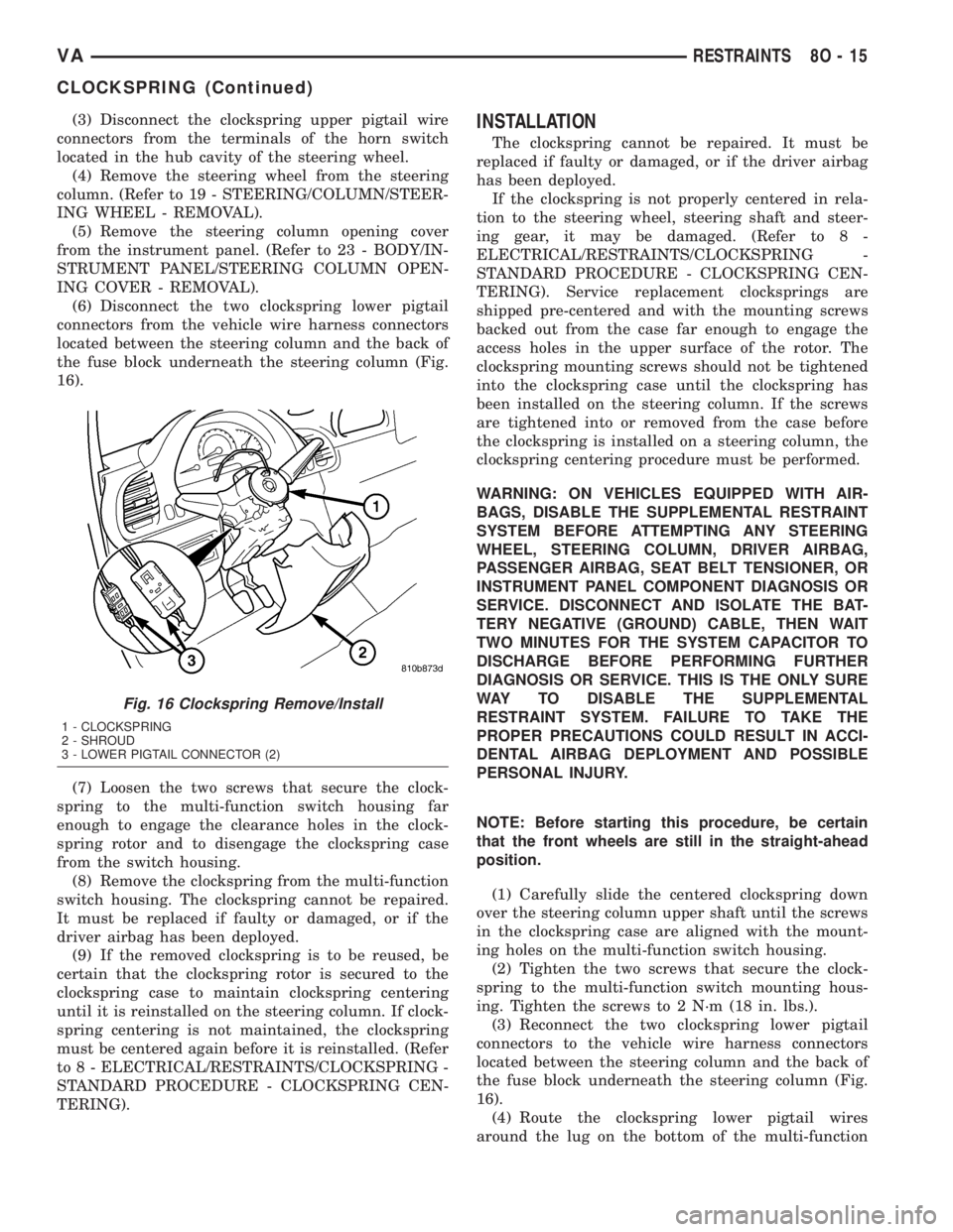
(6) Disconnect the two clockspring lower pigtail
connectors from the vehicle wire harness connectors
located between the steering column and the back of
the fuse block underneath the steering column (Fig.
16).
(7) Loosen the two screws that secure the clock-
spring to the multi-function switch housing far
enough to engage the clearance holes in the clock-
spring rotor and to disengage the clockspring case
from the switch housing.
(8) Remove the clockspring from the multi-function
switch housing. The clockspring cannot be repaired.
It must be replaced if faulty or damaged, or if the
driver airbag has been deployed.
(9) If the removed clockspring is to be reused, be
certain that the clockspring rotor is secured to the
clockspring case to maintain clockspring centering
until it is reinstalled on the steering column. If clock-
spring centering is not maintained, the clockspring
must be centered again before it is reinstalled. (Refer
to 8 - ELECTRICAL/RESTRAINTS/CLOCKSPRING -
STANDARD PROCEDURE - CLOCKSPRING CEN-
TERING).INSTALLATION
The clockspring cannot be repaired. It must be
replaced if faulty or damaged, or if the driver airbag
has been deployed.
If the clockspring is not properly centered in rela-
tion to the steering wheel, steering shaft and steer-
ing gear, it may be damaged. (Refer to 8 -
ELECTRICAL/RESTRAINTS/CLOCKSPRING -
STANDARD PROCEDURE - CLOCKSPRING CEN-
TERING). Service replacement clocksprings are
shipped pre-centered and with the mounting screws
backed out from the case far enough to engage the
access holes in the upper surface of the rotor. The
clockspring mounting screws should not be tightened
into the clockspring case until the clockspring has
been installed on the steering column. If the screws
are tightened into or removed from the case before
the clockspring is installed on a steering column, the
clockspring centering procedure must be performed.
WARNING: ON VEHICLES EQUIPPED WITH AIR-
BAGS, DISABLE THE SUPPLEMENTAL RESTRAINT
SYSTEM BEFORE ATTEMPTING ANY STEERING
WHEEL, STEERING COLUMN, DRIVER AIRBAG,
PASSENGER AIRBAG, SEAT BELT TENSIONER, OR
INSTRUMENT PANEL COMPONENT DIAGNOSIS OR
SERVICE. DISCONNECT AND ISOLATE THE BAT-
TERY NEGATIVE (GROUND) CABLE, THEN WAIT
TWO MINUTES FOR THE SYSTEM CAPACITOR TO
DISCHARGE BEFORE PERFORMING FURTHER
DIAGNOSIS OR SERVICE. THIS IS THE ONLY SURE
WAY TO DISABLE THE SUPPLEMENTAL
RESTRAINT SYSTEM. FAILURE TO TAKE THE
PROPER PRECAUTIONS COULD RESULT IN ACCI-
DENTAL AIRBAG DEPLOYMENT AND POSSIBLE
PERSONAL INJURY.
NOTE: Before starting this procedure, be certain
that the front wheels are still in the straight-ahead
position.
(1) Carefully slide the centered clockspring down
over the steering column upper shaft until the screws
in the clockspring case are aligned with the mount-
ing holes on the multi-function switch housing.
(2) Tighten the two screws that secure the clock-
spring to the multi-function switch mounting hous-
ing. Tighten the screws to 2 N´m (18 in. lbs.).
(3) Reconnect the two clockspring lower pigtail
connectors to the vehicle wire harness connectors
located between the steering column and the back of
the fuse block underneath the steering column (Fig.
16).
(4) Route the clockspring lower pigtail wires
around the lug on the bottom of the multi-function
Fig. 16 Clockspring Remove/Install
1 - CLOCKSPRING
2 - SHROUD
3 - LOWER PIGTAIL CONNECTOR (2)
VARESTRAINTS 8O - 15
CLOCKSPRING (Continued)
Page 254 of 1232
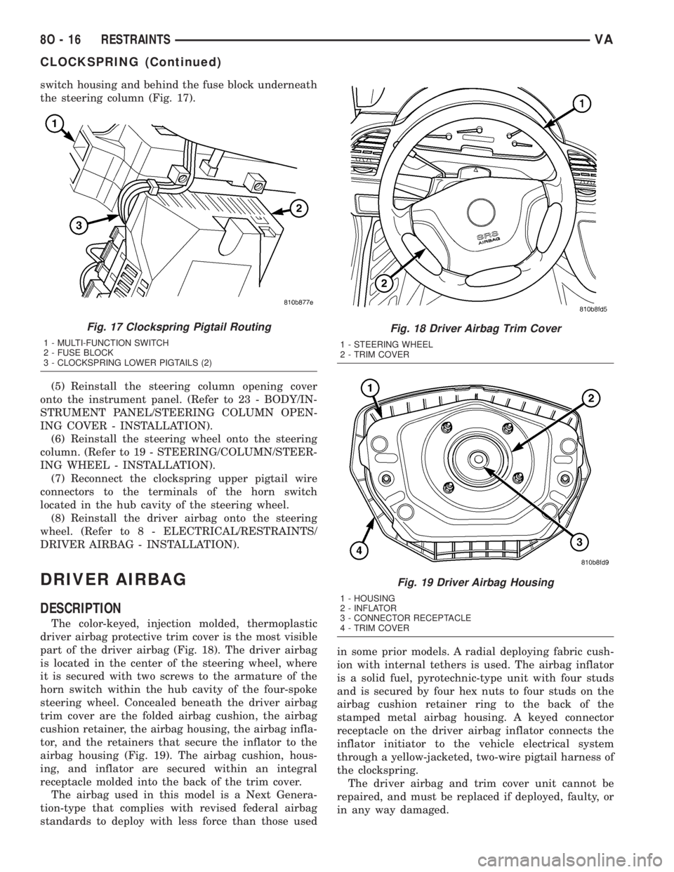
switch housing and behind the fuse block underneath
the steering column (Fig. 17).
(5) Reinstall the steering column opening cover
onto the instrument panel. (Refer to 23 - BODY/IN-
STRUMENT PANEL/STEERING COLUMN OPEN-
ING COVER - INSTALLATION).
(6) Reinstall the steering wheel onto the steering
column. (Refer to 19 - STEERING/COLUMN/STEER-
ING WHEEL - INSTALLATION).
(7) Reconnect the clockspring upper pigtail wire
connectors to the terminals of the horn switch
located in the hub cavity of the steering wheel.
(8) Reinstall the driver airbag onto the steering
wheel. (Refer to 8 - ELECTRICAL/RESTRAINTS/
DRIVER AIRBAG - INSTALLATION).
DRIVER AIRBAG
DESCRIPTION
The color-keyed, injection molded, thermoplastic
driver airbag protective trim cover is the most visible
part of the driver airbag (Fig. 18). The driver airbag
is located in the center of the steering wheel, where
it is secured with two screws to the armature of the
horn switch within the hub cavity of the four-spoke
steering wheel. Concealed beneath the driver airbag
trim cover are the folded airbag cushion, the airbag
cushion retainer, the airbag housing, the airbag infla-
tor, and the retainers that secure the inflator to the
airbag housing (Fig. 19). The airbag cushion, hous-
ing, and inflator are secured within an integral
receptacle molded into the back of the trim cover.
The airbag used in this model is a Next Genera-
tion-type that complies with revised federal airbag
standards to deploy with less force than those usedin some prior models. A radial deploying fabric cush-
ion with internal tethers is used. The airbag inflator
is a solid fuel, pyrotechnic-type unit with four studs
and is secured by four hex nuts to four studs on the
airbag cushion retainer ring to the back of the
stamped metal airbag housing. A keyed connector
receptacle on the driver airbag inflator connects the
inflator initiator to the vehicle electrical system
through a yellow-jacketed, two-wire pigtail harness of
the clockspring.
The driver airbag and trim cover unit cannot be
repaired, and must be replaced if deployed, faulty, or
in any way damaged.
Fig. 17 Clockspring Pigtail Routing
1 - MULTI-FUNCTION SWITCH
2 - FUSE BLOCK
3 - CLOCKSPRING LOWER PIGTAILS (2)
Fig. 18 Driver Airbag Trim Cover
1 - STEERING WHEEL
2 - TRIM COVER
Fig. 19 Driver Airbag Housing
1 - HOUSING
2 - INFLATOR
3 - CONNECTOR RECEPTACLE
4 - TRIM COVER
8O - 16 RESTRAINTSVA
CLOCKSPRING (Continued)
Page 256 of 1232
(1) Disconnect and isolate the battery negative
cable. Wait two minutes for the system capacitor to
discharge before further service.
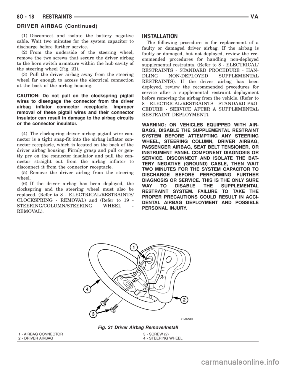
(2) From the underside of the steering wheel,
remove the two screws that secure the driver airbag
to the horn switch armature within the hub cavity of
the steering wheel (Fig. 21).
(3) Pull the driver airbag away from the steering
wheel far enough to access the electrical connection
at the back of the airbag housing.
CAUTION: Do not pull on the clockspring pigtail
wires to disengage the connector from the driver
airbag inflator connector receptacle. Improper
removal of these pigtail wires and their connector
insulator can result in damage to the airbag circuits
or the connector insulator.
(4) The clockspring driver airbag pigtail wire con-
nector is a tight snap-fit into the airbag inflator con-
nector receptacle, which is located on the back of the
driver airbag housing. Firmly grasp and pull or gen-
tly pry on the connector insulator and pull the con-
nector straight out from the airbag inflator to
disconnect it from the connector receptacle.
(5) Remove the driver airbag from the steering
wheel.
(6) If the driver airbag has been deployed, the
clockspring and the steering wheel must also be
replaced. (Refer to 8 - ELECTRICAL/RESTRAINTS/
CLOCKSPRING - REMOVAL) and (Refer to 19 -
STEERING/COLUMN/STEERING WHEEL -
REMOVAL).INSTALLATION
The following procedure is for replacement of a
faulty or damaged driver airbag. If the airbag is
faulty or damaged, but not deployed, review the rec-
ommended procedures for handling non-deployed
supplemental restraints. (Refer to 8 - ELECTRICAL/
RESTRAINTS - STANDARD PROCEDURE - HAN-
DLING NON-DEPLOYED SUPPLEMENTAL
RESTRAINTS). If the driver airbag has been
deployed, review the recommended procedures for
service after a supplemental restraint deployment
before removing the airbag from the vehicle. (Refer to
8 - ELECTRICAL/RESTRAINTS - STANDARD PRO-
CEDURE - SERVICE AFTER A SUPPLEMENTAL
RESTRAINT DEPLOYMENT).
WARNING: ON VEHICLES EQUIPPED WITH AIR-
BAGS, DISABLE THE SUPPLEMENTAL RESTRAINT
SYSTEM BEFORE ATTEMPTING ANY STEERING
WHEEL, STEERING COLUMN, DRIVER AIRBAG,
PASSENGER AIRBAG, SEAT BELT TENSIONER, OR
INSTRUMENT PANEL COMPONENT DIAGNOSIS OR
SERVICE. DISCONNECT AND ISOLATE THE BAT-
TERY NEGATIVE (GROUND) CABLE, THEN WAIT
TWO MINUTES FOR THE SYSTEM CAPACITOR TO
DISCHARGE BEFORE PERFORMING FURTHER
DIAGNOSIS OR SERVICE. THIS IS THE ONLY SURE
WAY TO DISABLE THE SUPPLEMENTAL
RESTRAINT SYSTEM. FAILURE TO TAKE THE
PROPER PRECAUTIONS COULD RESULT IN ACCI-
DENTAL AIRBAG DEPLOYMENT AND POSSIBLE
PERSONAL INJURY.
Fig. 21 Driver Airbag Remove/Install
1 - AIRBAG CONNECTOR
2 - DRIVER AIRBAG3 - SCREW (2)
4 - STEERING WHEEL
8O - 18 RESTRAINTSVA
DRIVER AIRBAG (Continued)
Page 257 of 1232
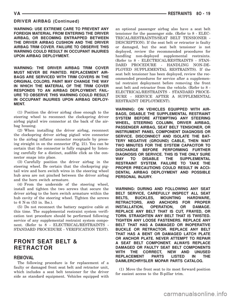
WARNING: USE EXTREME CARE TO PREVENT ANY
FOREIGN MATERIAL FROM ENTERING THE DRIVER
AIRBAG, OR BECOMING ENTRAPPED BETWEEN
THE DRIVER AIRBAG CUSHION AND THE DRIVER
AIRBAG TRIM COVER. FAILURE TO OBSERVE THIS
WARNING COULD RESULT IN OCCUPANT INJURIES
UPON AIRBAG DEPLOYMENT.
WARNING: THE DRIVER AIRBAG TRIM COVER
MUST NEVER BE PAINTED. REPLACEMENT AIR-
BAGS ARE SERVICED WITH TRIM COVERS IN THE
ORIGINAL COLORS. PAINT MAY CHANGE THE WAY
IN WHICH THE MATERIAL OF THE TRIM COVER
RESPONDS TO AN AIRBAG DEPLOYMENT. FAIL-
URE TO OBSERVE THIS WARNING COULD RESULT
IN OCCUPANT INJURIES UPON AIRBAG DEPLOY-
MENT.
(1) Position the driver airbag close enough to the
steering wheel to reconnect the clockspring driver
airbag pigtail wire connector at the back of the air-
bag housing.
(2) When installing the driver airbag, reconnect
the clockspring driver airbag pigtail wire connector
to the airbag inflator connector receptacle by press-
ing straight in on the connector (Fig. 21). You can be
certain that the connector is fully engaged by listen-
ing carefully for a distinct, audible click as the con-
nector snaps into place.
(3) Carefully position the driver airbag in the
steering wheel. Be certain that the clockspring pig-
tail wire and horn switch wires in the steering wheel
hub area are not pinched between the driver airbag
and the horn switch armature.
(4) From the underside of the steering wheel,
install and tighten the two screws that secure the
driver airbag to the horn switch armature within the
hub cavity of the steering wheel. Tighten the screws
to 6 N´m (53 in. lbs.).
(5) Do not reconnect the battery negative cable at
this time. The supplemental restraint system verifi-
cation test procedure should be performed following
service of any supplemental restraint system compo-
nent. (Refer to 8 - ELECTRICAL/RESTRAINTS -
STANDARD PROCEDURE - VERIFICATION TEST).
FRONT SEAT BELT &
RETRACTOR
REMOVAL
The following procedure is for replacement of a
faulty or damaged front seat belt and retractor unit,
which includes a seat belt tensioner for the driver
side as standard equipment. Vehicles equipped withan optional passenger airbag also have a seat belt
tensioner for the passenger side. (Refer to 8 - ELEC-
TRICAL/RESTRAINTS/SEAT BELT TENSIONER -
DESCRIPTION). If the seat belt or retractor is faulty
or damaged, but the seat belt tensioner is not
deployed, review the recommended procedures for
handling non-deployed supplemental restraints.
(Refer to 8 - ELECTRICAL/RESTRAINTS - STAN-
DARD PROCEDURE - HANDLING NON-DE-
PLOYED SUPPLEMENTAL RESTRAINTS). If the
seat belt tensioner has been deployed, review the rec-
ommended procedures for service after a supplemen-
tal restraint deployment before removing the front
seat belt and retractor from the vehicle. (Refer to 8 -
ELECTRICAL/RESTRAINTS - STANDARD PROCE-
DURE - SERVICE AFTER A SUPPLEMENTAL
RESTRAINT DEPLOYMENT).
WARNING: ON VEHICLES EQUIPPED WITH AIR-
BAGS, DISABLE THE SUPPLEMENTAL RESTRAINT
SYSTEM BEFORE ATTEMPTING ANY STEERING
WHEEL, STEERING COLUMN, DRIVER AIRBAG,
PASSENGER AIRBAG, SEAT BELT TENSIONER, OR
INSTRUMENT PANEL COMPONENT DIAGNOSIS OR
SERVICE. DISCONNECT AND ISOLATE THE BAT-
TERY NEGATIVE (GROUND) CABLE, THEN WAIT
TWO MINUTES FOR THE SYSTEM CAPACITOR TO
DISCHARGE BEFORE PERFORMING FURTHER
DIAGNOSIS OR SERVICE. THIS IS THE ONLY SURE
WAY TO DISABLE THE SUPPLEMENTAL
RESTRAINT SYSTEM. FAILURE TO TAKE THE
PROPER PRECAUTIONS COULD RESULT IN ACCI-
DENTAL AIRBAG DEPLOYMENT AND POSSIBLE
PERSONAL INJURY.
WARNING: DURING AND FOLLOWING ANY SEAT
BELT SERVICE, CAREFULLY INSPECT ALL SEAT
BELTS, BUCKLES, MOUNTING HARDWARE,
RETRACTORS, AND ANCHORS FOR PROPER
INSTALLATION, OPERATION, OR DAMAGE.
REPLACE ANY BELT THAT IS CUT, FRAYED, OR
TORN. STRAIGHTEN ANY BELT THAT IS TWISTED.
TIGHTEN ANY LOOSE FASTENERS. REPLACE ANY
BELT THAT HAS A DAMAGED OR INOPERATIVE
BUCKLE OR RETRACTOR. REPLACE ANY BELT
THAT HAS A BENT OR DAMAGED LATCH PLATE
OR ANCHOR PLATE. NEVER ATTEMPT TO REPAIR
A SEAT BELT COMPONENT. ALWAYS REPLACE
DAMAGED OR FAULTY SEAT BELT COMPONENTS
WITH THE CORRECT, NEW AND UNUSED
REPLACEMENT PARTS LISTED IN THE
DAIMLERCHRYSLER MOPAR PARTS CATALOG.
(1) Move the front seat to its most forward position
for easiest access to the B-pillar trim.
VARESTRAINTS 8O - 19
DRIVER AIRBAG (Continued)
Page 317 of 1232
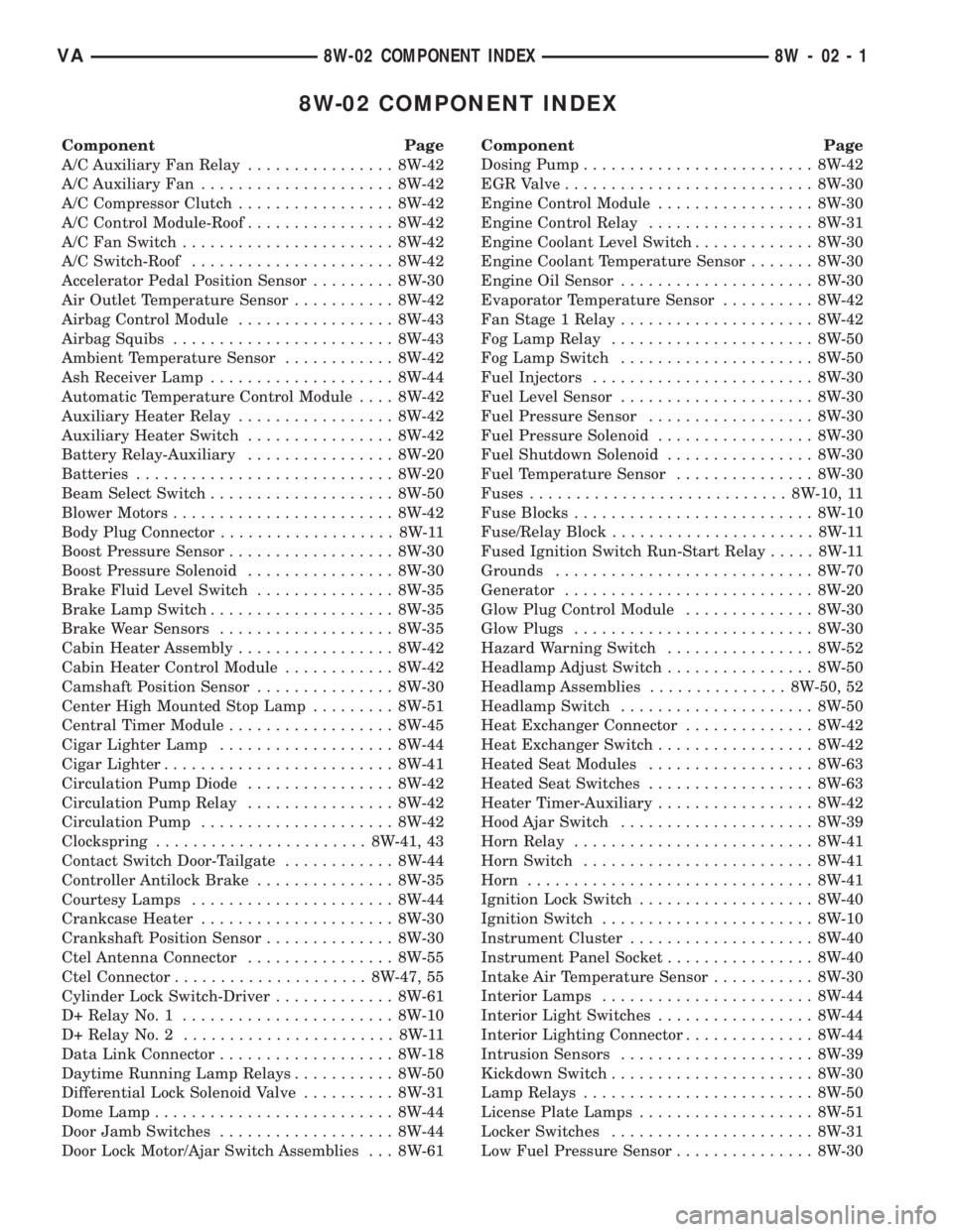
8W-02 COMPONENT INDEX
Component Page
A/C Auxiliary Fan Relay................ 8W-42
A/C Auxiliary Fan..................... 8W-42
A/C Compressor Clutch................. 8W-42
A/C Control Module-Roof................ 8W-42
A/C Fan Switch....................... 8W-42
A/C Switch-Roof...................... 8W-42
Accelerator Pedal Position Sensor......... 8W-30
Air Outlet Temperature Sensor........... 8W-42
Airbag Control Module................. 8W-43
Airbag Squibs........................ 8W-43
Ambient Temperature Sensor............ 8W-42
Ash Receiver Lamp.................... 8W-44
Automatic Temperature Control Module.... 8W-42
Auxiliary Heater Relay................. 8W-42
Auxiliary Heater Switch................ 8W-42
Battery Relay-Auxiliary................ 8W-20
Batteries............................ 8W-20
Beam Select Switch.................... 8W-50
Blower Motors........................ 8W-42
Body Plug Connector................... 8W-11
Boost Pressure Sensor.................. 8W-30
Boost Pressure Solenoid................ 8W-30
Brake Fluid Level Switch............... 8W-35
Brake Lamp Switch.................... 8W-35
Brake Wear Sensors................... 8W-35
Cabin Heater Assembly................. 8W-42
Cabin Heater Control Module............ 8W-42
Camshaft Position Sensor............... 8W-30
Center High Mounted Stop Lamp......... 8W-51
Central Timer Module.................. 8W-45
Cigar Lighter Lamp................... 8W-44
Cigar Lighter......................... 8W-41
Circulation Pump Diode................ 8W-42
Circulation Pump Relay................ 8W-42
Circulation Pump..................... 8W-42
Clockspring....................... 8W-41, 43
Contact Switch Door-Tailgate............ 8W-44
Controller Antilock Brake............... 8W-35
Courtesy Lamps...................... 8W-44
Crankcase Heater..................... 8W-30
Crankshaft Position Sensor.............. 8W-30
Ctel Antenna Connector................ 8W-55
Ctel Connector..................... 8W-47, 55
Cylinder Lock Switch-Driver............. 8W-61
D+ Relay No. 1....................... 8W-10
D+ Relay No. 2....................... 8W-11
Data Link Connector................... 8W-18
Daytime Running Lamp Relays........... 8W-50
Differential Lock Solenoid Valve.......... 8W-31
Dome Lamp.......................... 8W-44
Door Jamb Switches................... 8W-44
Door Lock Motor/Ajar Switch Assemblies . . . 8W-61Component Page
Dosing Pump......................... 8W-42
EGR Valve........................... 8W-30
Engine Control Module................. 8W-30
Engine Control Relay.................. 8W-31
Engine Coolant Level Switch............. 8W-30
Engine Coolant Temperature Sensor....... 8W-30
Engine Oil Sensor..................... 8W-30
Evaporator Temperature Sensor.......... 8W-42
Fan Stage 1 Relay..................... 8W-42
Fog Lamp Relay...................... 8W-50
Fog Lamp Switch..................... 8W-50
Fuel Injectors........................ 8W-30
Fuel Level Sensor..................... 8W-30
Fuel Pressure Sensor.................. 8W-30
Fuel Pressure Solenoid................. 8W-30
Fuel Shutdown Solenoid................ 8W-30
Fuel Temperature Sensor............... 8W-30
Fuses............................ 8W-10, 11
Fuse Blocks.......................... 8W-10
Fuse/Relay Block...................... 8W-11
Fused Ignition Switch Run-Start Relay..... 8W-11
Grounds............................ 8W-70
Generator........................... 8W-20
Glow Plug Control Module.............. 8W-30
Glow Plugs.......................... 8W-30
Hazard Warning Switch................ 8W-52
Headlamp Adjust Switch................ 8W-50
Headlamp Assemblies............... 8W-50, 52
Headlamp Switch..................... 8W-50
Heat Exchanger Connector.............. 8W-42
Heat Exchanger Switch................. 8W-42
Heated Seat Modules.................. 8W-63
Heated Seat Switches.................. 8W-63
Heater Timer-Auxiliary................. 8W-42
Hood Ajar Switch..................... 8W-39
Horn Relay.......................... 8W-41
Horn Switch......................... 8W-41
Horn............................... 8W-41
Ignition Lock Switch................... 8W-40
Ignition Switch....................... 8W-10
Instrument Cluster.................... 8W-40
Instrument Panel Socket................ 8W-40
Intake Air Temperature Sensor........... 8W-30
Interior Lamps....................... 8W-44
Interior Light Switches................. 8W-44
Interior Lighting Connector.............. 8W-44
Intrusion Sensors..................... 8W-39
Kickdown Switch...................... 8W-30
Lamp Relays......................... 8W-50
License Plate Lamps................... 8W-51
Locker Switches...................... 8W-31
Low Fuel Pressure Sensor............... 8W-30
VA8W-02 COMPONENT INDEX 8W - 02 - 1
Page 393 of 1232
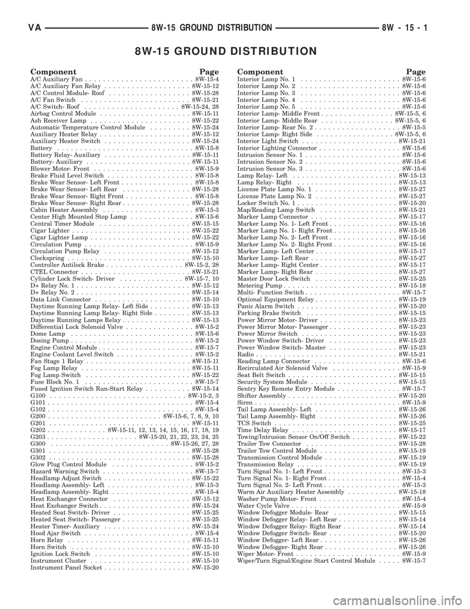
8W-15 GROUND DISTRIBUTION
Component PageA/C Auxiliary Fan........................8W-15-4
A/C Auxiliary Fan Relay...................8W-15-12
A/C Control Module- Roof..................8W-15-28
A/C Fan Switch........................8W-15-21
A/C Switch- Roof.....................8W-15-24, 28
Airbag Control Module....................8W-15-11
Ash Receiver Lamp......................8W-15-22
Automatic Temperature Control Module.........8W-15-24
Auxiliary Heater Relay....................8W-15-12
Auxiliary Heater Switch...................8W-15-24
Battery..............................8W-15-8
Battery Relay- Auxiliary...................8W-15-11
Battery- Auxiliary.......................8W-15-11
Blower Motor- Front......................8W-15-9
Brake Fluid Level Switch...................8W-15-8
Brake Wear Sensor- Left Front................8W-15-8
Brake Wear Sensor- Left Rear...............8W-15-28
Brake Wear Sensor- Right Front...............8W-15-8
Brake Wear Sensor- Right Rear...............8W-15-28
Cabin Heater Assembly....................8W-15-3
Center High Mounted Stop Lamp..............8W-15-6
Central Timer Module....................8W-15-15
Cigar Lighter..........................8W-15-22
Cigar Lighter Lamp......................8W-15-22
Circulation Pump........................8W-15-9
Circulation Pump Relay...................8W-15-12
Clockspring...........................8W-15-10
Controller Antilock Brake.................8W-15-2, 28
CTEL Connector........................8W-15-21
Cylinder Lock Switch- Driver..............8W-15-7, 10
D+ Relay No. 1.........................8W-15-12
D+ Relay No. 2.........................8W-15-14
Data Link Connector.....................8W-15-10
Daytime Running Lamp Relay- Left Side.........8W-15-13
Daytime Running Lamp Relay- Right Side........8W-15-13
Daytime Running Lamps Relay...............8W-15-13
Differential Lock Solenoid Valve...............8W-15-2
Dome Lamp...........................8W-15-6
Dosing Pump...........................8W-15-2
Engine Control Module.....................8W-15-7
Engine Coolant Level Switch.................8W-15-2
Fan Stage 1 Relay.......................8W-15-11
Fog Lamp Relay........................8W-15-11
Fog Lamp Switch.......................8W-15-22
Fuse Block No. 1........................8W-15-7
Fused Ignition Switch Run-Start Relay..........8W-15-14
G100..............................8W-15-2, 3
G101................................8W-15-4
G102................................8W-15-4
G200.........................8W-15-6, 7, 8, 9, 10
G201...............................8W-15-11
G202.............8W-15-11, 12, 13, 14, 15, 16, 17, 18, 19
G203....................8W-15-20, 21, 22, 23, 24, 25
G300..........................8W-15-26, 27, 28
G301...............................8W-15-28
G302...............................8W-15-28
Glow Plug Control Module..................8W-15-2
Hazard Warning Switch....................8W-15-7
Headlamp Adjust Switch...................8W-15-22
Headlamp Assembly- Left...................8W-15-3
Headlamp Assembly- Right..................8W-15-4
Heat Exchanger Connector.................8W-15-12
Heat Exchanger Switch....................8W-15-24
Heated Seat Switch- Driver.................8W-15-25
Heated Seat Switch- Passenger...............8W-15-25
Heater Timer- Auxiliary...................8W-15-24
Hood Ajar Switch........................8W-15-4
Horn Relay...........................8W-15-11
Horn Switch..........................8W-15-10
Ignition Lock Switch.....................8W-15-10
Instrument Cluster......................8W-15-10
Instrument Panel Socket...................8W-15-20Component PageInterior Lamp No. 1......................8W-15-6
Interior Lamp No. 2......................8W-15-6
Interior Lamp No. 3......................8W-15-6
Interior Lamp No. 4......................8W-15-6
Interior Lamp No. 5......................8W-15-6
Interior Lamp- Middle Front................8W-15-5, 6
Interior Lamp- Middle Rear................8W-15-5, 6
Interior Lamp- Rear No. 2...................8W-15-5
Interior Lamp- Right Side.................8W-15-5, 6
Interior Light Switch.....................8W-15-21
Interior Lighting Connector..................8W-15-6
Intrusion Sensor No. 1.....................8W-15-6
Intrusion Sensor No. 2.....................8W-15-6
Intrusion Sensor No. 3.....................8W-15-6
Lamp Relay- Left.......................8W-15-13
Lamp Relay- Right......................8W-15-13
License Plate Lamp No. 1..................8W-15-27
License Plate Lamp No. 2..................8W-15-27
Locker Switch No. 1......................8W-15-20
Map/Reading Lamp Switch.................8W-15-21
Marker Lamp Connector...................8W-15-17
Marker Lamp No. 1- Left Front...............8W-15-16
Marker Lamp No. 1- Right Front..............8W-15-16
Marker Lamp No. 2- Left Front...............8W-15-16
Marker Lamp No. 2- Right Front..............8W-15-16
Marker Lamp- Left Center..................8W-15-17
Marker Lamp- Left Rear...................8W-15-27
Marker Lamp- Right Center.................8W-15-17
Marker Lamp- Right Rear..................8W-15-27
Master Door Lock Switch..................8W-15-25
Metering Pump.........................8W-15-18
Multi- Function Switch.....................8W-15-7
Optional Equipment Relay..................8W-15-19
Panic Alarm Switch......................8W-15-20
Parking Brake Switch....................8W-15-15
Power Mirror Motor- Driver.................8W-15-23
Power Mirror Motor- Passenger...............8W-15-23
Power Mirror Switch.....................8W-15-23
Power Window Switch- Driver...............8W-15-23
Power Window Switch- Master...............8W-15-23
Radio...............................8W-15-21
Reading Lamp Connector...................8W-15-6
Recirculated Air Solenoid Valve...............8W-15-9
Seat Belt Switch........................8W-15-15
Security System Module...................8W-15-15
Sentry Key Remote Entry Module..............8W-15-7
Shifter Assembly........................8W-15-20
Siren................................8W-15-9
Tail Lamp Assembly- Left..................8W-15-26
Tail Lamp Assembly- Right.................8W-15-26
TCS Switch...........................8W-15-25
Time Delay Relay.......................8W-15-17
Towing/Intrusion Sensor On/Off Switch..........8W-15-22
Trailer Tow Connector....................8W-15-28
Trailer Tow Control Module.................8W-15-19
Transmission Control Module................8W-15-19
Transmission Relay......................8W-15-19
Turn Signal No. 1- Left Front.................8W-15-3
Turn Signal No. 1- Right Front................8W-15-4
Turn Signal No. 2- Left Front.................8W-15-3
Warm Air Auxiliary Heater Assembly...........8W-15-18
Washer Pump Motor- Front..................8W-15-4
Water Cycle Valve........................8W-15-9
Window Defogger Module- Rear..............8W-15-15
Window Defogger Relay- Left Rear.............8W-15-14
Window Defogger Relay- Right Rear............8W-15-14
Window Defogger Switch- Rear...............8W-15-20
Window Defogger- Left Rear.................8W-15-26
Window Defogger- Right Rear................8W-15-26
Wiper Motor- Front.......................8W-15-9
Wiper/Turn Signal/Engine Start Control Module.....8W-15-7
VA8W-15 GROUND DISTRIBUTION 8W - 15 - 1
Page 497 of 1232
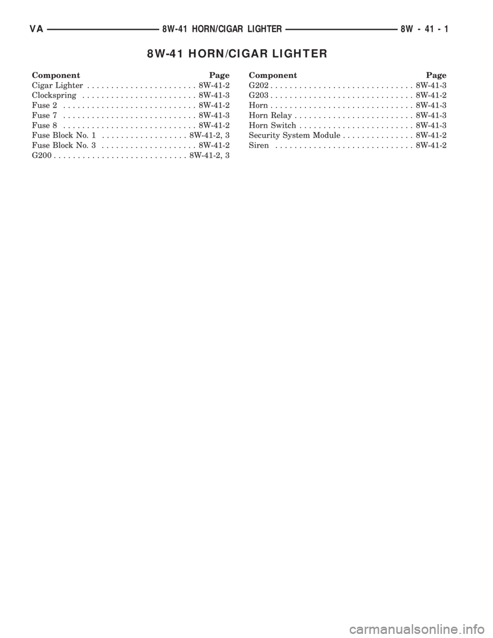
8W-41 HORN/CIGAR LIGHTER
Component Page
Cigar Lighter....................... 8W-41-2
Clockspring........................ 8W-41-3
Fuse 2............................ 8W-41-2
Fuse 7............................ 8W-41-3
Fuse 8............................ 8W-41-2
Fuse Block No. 1.................. 8W-41-2, 3
Fuse Block No. 3.................... 8W-41-2
G200............................ 8W-41-2, 3Component Page
G202.............................. 8W-41-3
G203.............................. 8W-41-2
Horn.............................. 8W-41-3
Horn Relay......................... 8W-41-3
Horn Switch........................ 8W-41-3
Security System Module............... 8W-41-2
Siren............................. 8W-41-2
VA8W-41 HORN/CIGAR LIGHTER 8W - 41 - 1