2005 MERCEDES-BENZ SPRINTER Steering wheel
[x] Cancel search: Steering wheelPage 287 of 1232
and methods. Proper testing of the intermittent wipe
logic circuitry within the fuse block requires the use
of a DRBIIItscan tool. Refer to the appropriate diag-
nostic information. Refer to the owner's manual in
the vehicle glove box for more information on the fea-
tures and operation of the wiper and washer system.
DIAGNOSIS AND TESTING - WIPER &
WASHER SYSTEM
If the wiper motor operates, but the wipers do not
move on the windshield, replace the faulty wiper
linkage module. If the washer pump/motor operates,
but no washer fluid is dispensed on the glass; or, if
the wipers operate, but chatter, lift, or do not clear
the glass, clean and inspect the wiper and washer
system components as required. (Refer to 8 - ELEC-
TRICAL/WIPERS/WASHERS - CLEANING) and
(Refer to 8 - ELECTRICAL/WIPERS/WASHERS -
INSPECTION). For diagnosis and testing of the
multi-function switch (Refer to 8 - ELECTRICAL/
LAMPS/LIGHTING - EXTERIOR/MULTI-FUNC-
TION SWITCH - DIAGNOSIS AND TESTING).
Refer to the appropriate wiring information. The wir-
ing information includes wiring diagrams, proper
wire and connector repair procedures, details of wire
harness routing and retention, connector pin-out
information and location views for the various wire
harness connectors, splices and grounds.
The hard wired circuits and components of the
wiper and washer system may be diagnosed and
tested using conventional diagnostic tools and proce-
dures. However, conventional diagnostic methods
may not prove conclusive in the diagnosis of the
intermittent wipe logic circuitry contained within the
fuse block underneath the steering column. The most
reliable, efficient, and accurate means to diagnose
the intermittent wipe logic circuitry requires the use
of a DRBIIItscan tool. Refer to the appropriate diag-
nostic information.
WARNING: ON VEHICLES EQUIPPED WITH AIR-
BAGS, DISABLE THE SUPPLEMENTAL RESTRAINT
SYSTEM BEFORE ATTEMPTING ANY STEERING
WHEEL, STEERING COLUMN, DRIVER AIRBAG,
PASSENGER AIRBAG, SEAT BELT TENSIONER, OR
INSTRUMENT PANEL COMPONENT DIAGNOSIS OR
SERVICE. DISCONNECT AND ISOLATE THE BAT-
TERY NEGATIVE (GROUND) CABLE, THEN WAIT
TWO MINUTES FOR THE SYSTEM CAPACITOR TO
DISCHARGE BEFORE PERFORMING FURTHER
DIAGNOSIS OR SERVICE. THIS IS THE ONLY SURE
WAY TO DISABLE THE SUPPLEMENTAL
RESTRAINT SYSTEM. FAILURE TO TAKE THE
PROPER PRECAUTIONS COULD RESULT IN ACCI-
DENTAL AIRBAG DEPLOYMENT AND POSSIBLE
PERSONAL INJURY.
CLEANING - WIPER & WASHER SYSTEM
WIPER SYSTEM
The squeegees of wiper blades exposed to the ele-
ments for a long time tend to lose their wiping effec-
tiveness. Periodic cleaning of the squeegees is
suggested to remove any deposits of salt or road film.
The wiper blades, arms, and windshield glass should
only be cleaned using a sponge or soft cloth and
windshield washer fluid, a mild detergent, or a non-
abrasive cleaner. If the wiper blades continue to
leave streaks, smears, hazing, or beading on the
glass after thorough cleaning of the squeegees and
the glass, the entire wiper blade assembly must be
replaced.
CAUTION: Protect the rubber squeegees of the
wiper blades from any petroleum-based cleaners,
solvents, or contaminants. These products can rap-
idly deteriorate the rubber squeegees.
WASHER SYSTEM
If the washer system is contaminated with foreign
material, drain the washer reservoir by removing the
washer pump/motor from the reservoir. Clean foreign
material from the inside of the washer pump/motor
inlet nipple and the washer reservoir using clean
washer fluid, a mild detergent, or a non-abrasive
cleaner. Flush foreign material from the washer sys-
tem plumbing by first disconnecting the washer
hoses from the washer nozzles, then running the
washer pump/motor to run clean washer fluid or
water through the system. Plugged or restricted
washer nozzles should be carefully back-flushed
using compressed air. If the washer nozzle obstruc-
tion cannot be cleared, replace the washer nozzle.
CAUTION: Never introduce petroleum-based clean-
ers, solvents, or contaminants into the washer sys-
tem. These products can rapidly deteriorate the
rubber seals and hoses of the washer system, as
well as the rubber squeegees of the wiper blades.
CAUTION: Never use compressed air to flush the
washer system plumbing. Compressed air pres-
sures are too great for the washer system plumbing
components and will result in further system dam-
age. Never use sharp instruments to clear a
plugged washer nozzle or damage to the nozzle ori-
fice and improper nozzle spray patterns will result.
VAWIPERS/WASHERS 8R - 5
WIPERS/WASHERS (Continued)
Page 304 of 1232
REMOVAL
WARNING: ON VEHICLES EQUIPPED WITH AIR-
BAGS, DISABLE THE SUPPLEMENTAL RESTRAINT
SYSTEM BEFORE ATTEMPTING ANY STEERING
WHEEL, STEERING COLUMN, DRIVER AIRBAG,
PASSENGER AIRBAG, SEAT BELT TENSIONER, OR
INSTRUMENT PANEL COMPONENT DIAGNOSIS OR
SERVICE. DISCONNECT AND ISOLATE THE BAT-
TERY NEGATIVE (GROUND) CABLE, THEN WAIT
TWO MINUTES FOR THE SYSTEM CAPACITOR TO
DISCHARGE BEFORE PERFORMING FURTHER
DIAGNOSIS OR SERVICE. THIS IS THE ONLY SURE
WAY TO DISABLE THE SUPPLEMENTAL
RESTRAINT SYSTEM. FAILURE TO TAKE THE
PROPER PRECAUTIONS COULD RESULT IN ACCI-
DENTAL AIRBAG DEPLOYMENT AND POSSIBLE
PERSONAL INJURY.
(1) Disconnect and isolate the battery negative
cable.
(2) Remove the fuse access panel from the steering
column opening cover below the steering column on
the instrument panel.
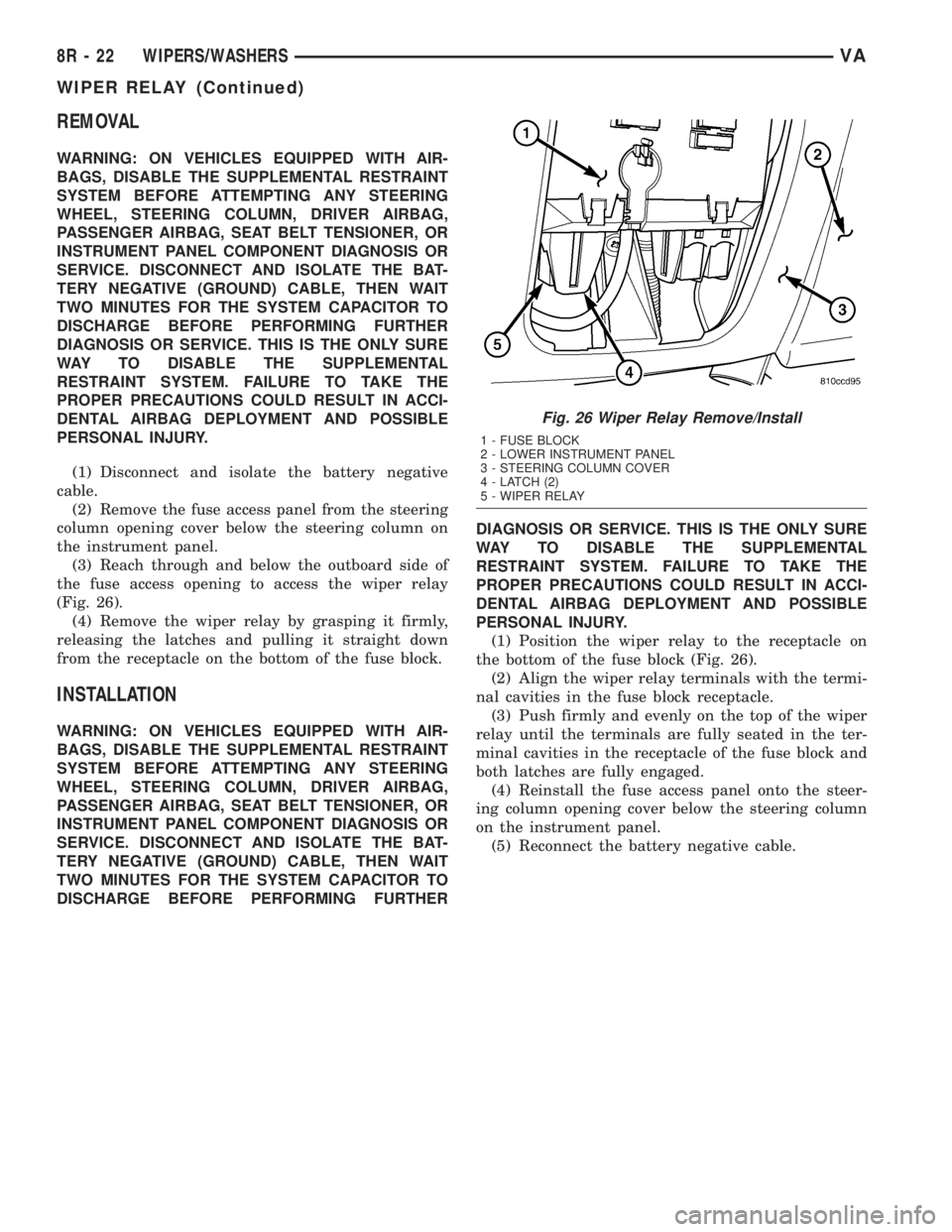
(3) Reach through and below the outboard side of
the fuse access opening to access the wiper relay
(Fig. 26).
(4) Remove the wiper relay by grasping it firmly,
releasing the latches and pulling it straight down
from the receptacle on the bottom of the fuse block.
INSTALLATION
WARNING: ON VEHICLES EQUIPPED WITH AIR-
BAGS, DISABLE THE SUPPLEMENTAL RESTRAINT
SYSTEM BEFORE ATTEMPTING ANY STEERING
WHEEL, STEERING COLUMN, DRIVER AIRBAG,
PASSENGER AIRBAG, SEAT BELT TENSIONER, OR
INSTRUMENT PANEL COMPONENT DIAGNOSIS OR
SERVICE. DISCONNECT AND ISOLATE THE BAT-
TERY NEGATIVE (GROUND) CABLE, THEN WAIT
TWO MINUTES FOR THE SYSTEM CAPACITOR TO
DISCHARGE BEFORE PERFORMING FURTHERDIAGNOSIS OR SERVICE. THIS IS THE ONLY SURE
WAY TO DISABLE THE SUPPLEMENTAL
RESTRAINT SYSTEM. FAILURE TO TAKE THE
PROPER PRECAUTIONS COULD RESULT IN ACCI-
DENTAL AIRBAG DEPLOYMENT AND POSSIBLE
PERSONAL INJURY.
(1) Position the wiper relay to the receptacle on
the bottom of the fuse block (Fig. 26).
(2) Align the wiper relay terminals with the termi-
nal cavities in the fuse block receptacle.
(3) Push firmly and evenly on the top of the wiper
relay until the terminals are fully seated in the ter-
minal cavities in the receptacle of the fuse block and
both latches are fully engaged.
(4) Reinstall the fuse access panel onto the steer-
ing column opening cover below the steering column
on the instrument panel.
(5) Reconnect the battery negative cable.
Fig. 26 Wiper Relay Remove/Install
1 - FUSE BLOCK
2 - LOWER INSTRUMENT PANEL
3 - STEERING COLUMN COVER
4 - LATCH (2)
5 - WIPER RELAY
8R - 22 WIPERS/WASHERSVA
WIPER RELAY (Continued)
Page 695 of 1232
8W-91 CONNECTOR/GROUND/SPLICE LOCATION
TABLE OF CONTENTS
page
CONNECTOR/GROUND/SPLICE LOCATION
DESCRIPTION..........................1
CONNECTOR/GROUND/SPLICE
LOCATION
DESCRIPTION
This section provides illustrations identifying con-
nector, ground, and splice locations in the vehicle.
Connector, ground, and splice indexes are provided.Use the wiring diagrams in each section for connec-
tor, ground, and splice identification. Refer to the
appropriate index for the proper figure number. For
items that are not shown in this section N/S is placed
in the Fig. column.
CONNECTORS
CONNECTOR NAME/
NUMBERCOLOR LOCATION FIG.
A/C Auxiliary Fan Engine Compartment N/S
A/C Auxiliary Fan Relay (In
Relay Block)Under Driver Seat N/S
A/C Control Module-Roof Instrument Panel N/S
A/C Fan Switch Instrument Panel N/S
A/C Switch - Roof Instrument Panel N/S
Accelerator Pedal Position
SensorOn Gas Pedal 14
Air Outlet Temperature
SensorEngine Compartment (Right Rear) 5,15
Airbag Control Module Under Driver Seat 10,16,18
Airbag Squib-Driver Steering Wheel 10
Airbag Squib-Passenger Instrument Panel (Passenger Side) N/S
Ambient Temperature Sensor Front Engine Compartment 2,15
Ash Receiver Lamp In Ash Tray N/S
Automatic Temperature
Control Module C1Instrument Panel N/S
Automatic Temperature
Control Module C2Instrument Panel N/S
Auxiliary Heater Relay (In
Relay Block)Under Driver Seat N/S
Auxiliary Heater Switch Instrument Panel N/S
Battery Relay-Auxiliary Engine Compartment N/S
Blower Motor Resistor Block Underhood Right (To The
Instrument Panel)4
VA8W-91 CONNECTOR/GROUND/SPLICE LOCATION 8W - 91 - 1
Page 697 of 1232
CONNECTOR NAME/
NUMBERCOLOR LOCATION FIG.
Cabin Heater Assembly C1 Instrument Panel N/S
Cabin Heater Assembly C2 Instrument Panel N/S
Camshaft Position Sensor Engine Compartment 7
Center High Mounted Stop
LampRear Vehicle N/S
Central Timer Module C1 Instrument Panel N/S
Central Timer Module C2 Instrument Panel N/S
Cigar Lighter Near Ash Tray N/S
Cigar Lighter Lamp Near Cigar Lighter N/S
Circulation Pump (Cabin
Heater Module)Engine Compartment-Front 4
Circulation Pump Diode Engine Compartment N/S
Circulation Pump Relay
(Relay Block)Under Driver Seat N/S
Clockspring C1 Steering Wheel 10
Clockspring C2 Steering Wheel 10,14
Contact Plate-Left Rear
License PlateRear Of Vehicle On Left N/S
Contact Switch Door-Right
RearRight Rear Door 21
Controller Antilock Brake Engine Compartment-Left 2
Courtesy Lamp - Driver Driver Door 20
Courtesy Lamp - Left Sliding
DoorLeft B-Pillar 20
Courtesy Lamp - Passenger
DoorPassenger Door 20
Courtesy Lamp - Right Rear
DoorRight Rear Door 20
Courtesy Lamp - Right
Sliding DoorRight B-Pillar 20
Crankcase Heater Engine Compartment N/S
Crankshaft Position Sensor On Engine N/S
CTEL Connector Instrument Panel N/S
Cylinder Lock Switch-Driver Driver Door 21
D(+) Relay Under Driver Seat N/S
Data Link Connector Under Dash N/S
Daytime Running Lamp
Relay (Relay Block)Under Driver Seat N/S
Daytime Running Lamp
Relay-Left Side (Relay Block)Under Driver Seat N/S
Daytime Running Lamp
Relay-Right Side (Relay
Block)Under Driver Seat N/S
Differential Lock Solenoid
ValveUnderbody 24
VA8W-91 CONNECTOR/GROUND/SPLICE LOCATION 8W - 91 - 3
CONNECTOR/GROUND/SPLICE LOCATION (Continued)
Page 700 of 1232
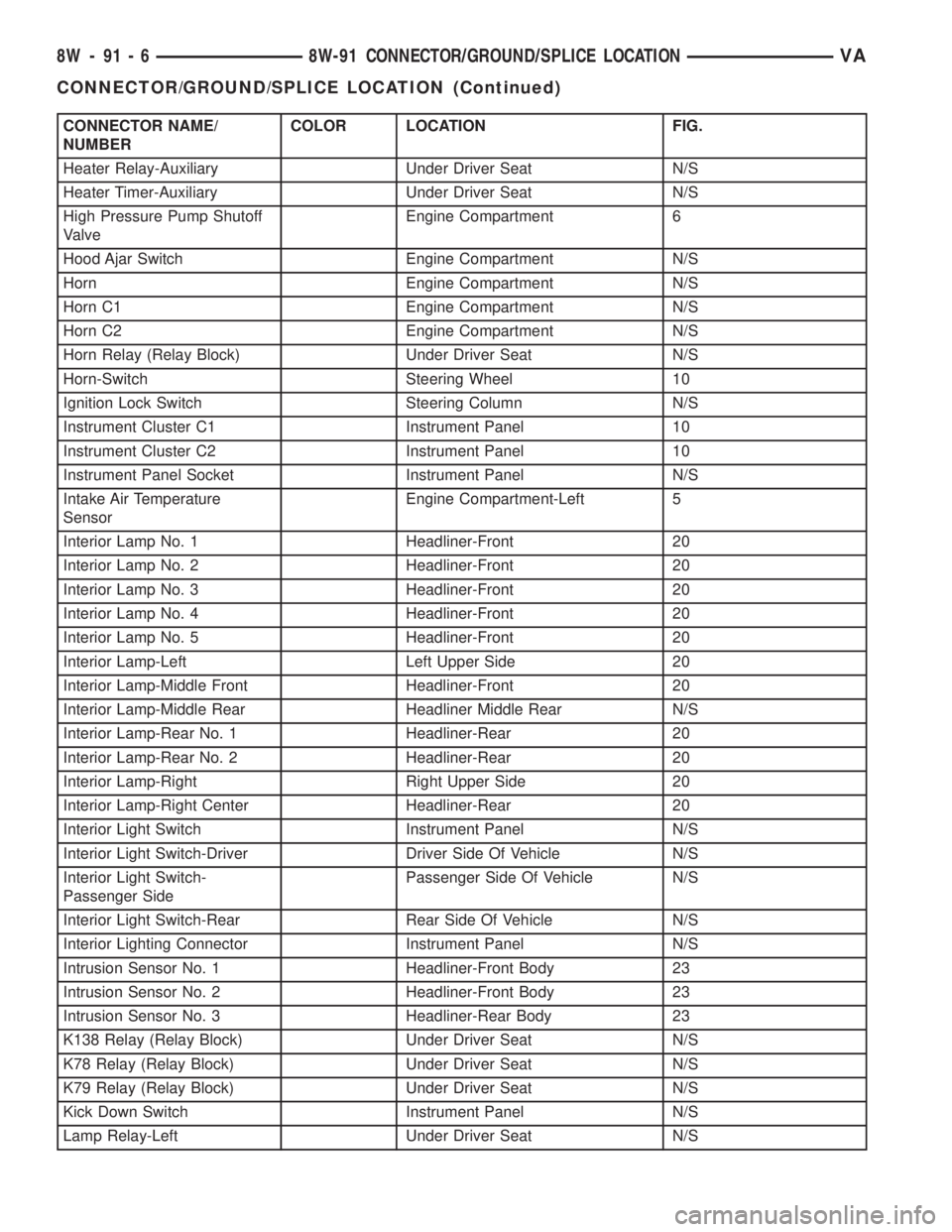
CONNECTOR NAME/
NUMBERCOLOR LOCATION FIG.
Heater Relay-Auxiliary Under Driver Seat N/S
Heater Timer-Auxiliary Under Driver Seat N/S
High Pressure Pump Shutoff
ValveEngine Compartment 6
Hood Ajar Switch Engine Compartment N/S
Horn Engine Compartment N/S
Horn C1 Engine Compartment N/S
Horn C2 Engine Compartment N/S
Horn Relay (Relay Block) Under Driver Seat N/S
Horn-Switch Steering Wheel 10
Ignition Lock Switch Steering Column N/S
Instrument Cluster C1 Instrument Panel 10
Instrument Cluster C2 Instrument Panel 10
Instrument Panel Socket Instrument Panel N/S
Intake Air Temperature
SensorEngine Compartment-Left 5
Interior Lamp No. 1 Headliner-Front 20
Interior Lamp No. 2 Headliner-Front 20
Interior Lamp No. 3 Headliner-Front 20
Interior Lamp No. 4 Headliner-Front 20
Interior Lamp No. 5 Headliner-Front 20
Interior Lamp-Left Left Upper Side 20
Interior Lamp-Middle Front Headliner-Front 20
Interior Lamp-Middle Rear Headliner Middle Rear N/S
Interior Lamp-Rear No. 1 Headliner-Rear 20
Interior Lamp-Rear No. 2 Headliner-Rear 20
Interior Lamp-Right Right Upper Side 20
Interior Lamp-Right Center Headliner-Rear 20
Interior Light Switch Instrument Panel N/S
Interior Light Switch-Driver Driver Side Of Vehicle N/S
Interior Light Switch-
Passenger SidePassenger Side Of Vehicle N/S
Interior Light Switch-Rear Rear Side Of Vehicle N/S
Interior Lighting Connector Instrument Panel N/S
Intrusion Sensor No. 1 Headliner-Front Body 23
Intrusion Sensor No. 2 Headliner-Front Body 23
Intrusion Sensor No. 3 Headliner-Rear Body 23
K138 Relay (Relay Block) Under Driver Seat N/S
K78 Relay (Relay Block) Under Driver Seat N/S
K79 Relay (Relay Block) Under Driver Seat N/S
Kick Down Switch Instrument Panel N/S
Lamp Relay-Left Under Driver Seat N/S
8W - 91 - 6 8W-91 CONNECTOR/GROUND/SPLICE LOCATIONVA
CONNECTOR/GROUND/SPLICE LOCATION (Continued)
Page 701 of 1232
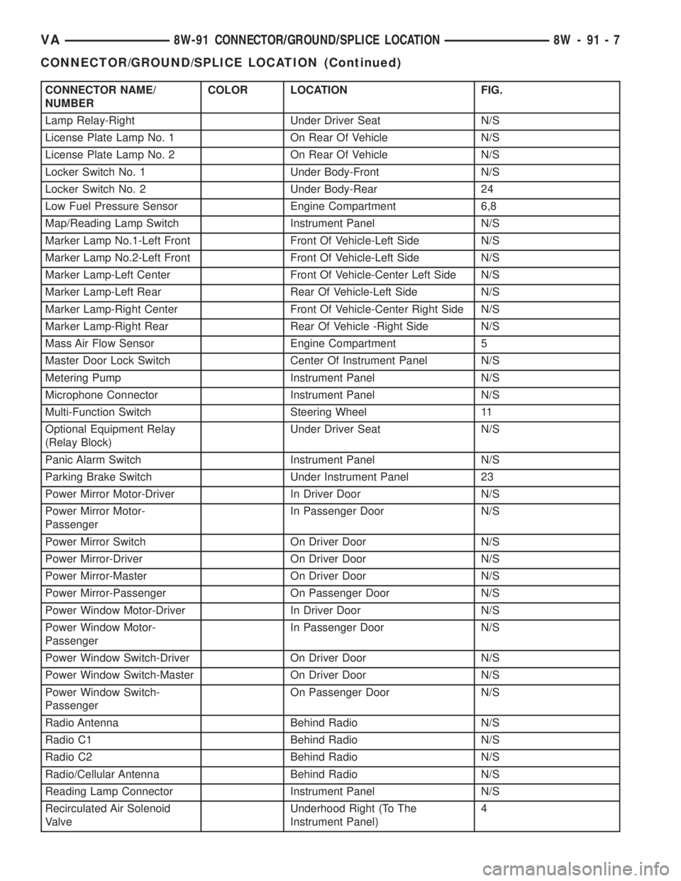
CONNECTOR NAME/
NUMBERCOLOR LOCATION FIG.
Lamp Relay-Right Under Driver Seat N/S
License Plate Lamp No. 1 On Rear Of Vehicle N/S
License Plate Lamp No. 2 On Rear Of Vehicle N/S
Locker Switch No. 1 Under Body-Front N/S
Locker Switch No. 2 Under Body-Rear 24
Low Fuel Pressure Sensor Engine Compartment 6,8
Map/Reading Lamp Switch Instrument Panel N/S
Marker Lamp No.1-Left Front Front Of Vehicle-Left Side N/S
Marker Lamp No.2-Left Front Front Of Vehicle-Left Side N/S
Marker Lamp-Left Center Front Of Vehicle-Center Left Side N/S
Marker Lamp-Left Rear Rear Of Vehicle-Left Side N/S
Marker Lamp-Right Center Front Of Vehicle-Center Right Side N/S
Marker Lamp-Right Rear Rear Of Vehicle -Right Side N/S
Mass Air Flow Sensor Engine Compartment 5
Master Door Lock Switch Center Of Instrument Panel N/S
Metering Pump Instrument Panel N/S
Microphone Connector Instrument Panel N/S
Multi-Function Switch Steering Wheel 11
Optional Equipment Relay
(Relay Block)Under Driver Seat N/S
Panic Alarm Switch Instrument Panel N/S
Parking Brake Switch Under Instrument Panel 23
Power Mirror Motor-Driver In Driver Door N/S
Power Mirror Motor-
PassengerIn Passenger Door N/S
Power Mirror Switch On Driver Door N/S
Power Mirror-Driver On Driver Door N/S
Power Mirror-Master On Driver Door N/S
Power Mirror-Passenger On Passenger Door N/S
Power Window Motor-Driver In Driver Door N/S
Power Window Motor-
PassengerIn Passenger Door N/S
Power Window Switch-Driver On Driver Door N/S
Power Window Switch-Master On Driver Door N/S
Power Window Switch-
PassengerOn Passenger Door N/S
Radio Antenna Behind Radio N/S
Radio C1 Behind Radio N/S
Radio C2 Behind Radio N/S
Radio/Cellular Antenna Behind Radio N/S
Reading Lamp Connector Instrument Panel N/S
Recirculated Air Solenoid
ValveUnderhood Right (To The
Instrument Panel)4
VA8W-91 CONNECTOR/GROUND/SPLICE LOCATION 8W - 91 - 7
CONNECTOR/GROUND/SPLICE LOCATION (Continued)
Page 702 of 1232
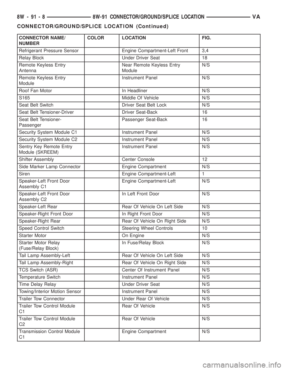
CONNECTOR NAME/
NUMBERCOLOR LOCATION FIG.
Refrigerant Pressure Sensor Engine Compartment-Left Front 3,4
Relay Block Under Driver Seat 18
Remote Keyless Entry
AntennaNear Remote Keyless Entry
ModuleN/S
Remote Keyless Entry
ModuleInstrument Panel N/S
Roof Fan Motor In Headliner N/S
S165 Middle Of Vehicle N/S
Seat Belt Switch Driver Seat Belt Lock N/S
Seat Belt Tensioner-Driver Driver Seat-Back 16
Seat Belt Tensioner-
PassengerPassenger Seat-Back 16
Security System Module C1 Instrument Panel N/S
Security System Module C2 Instrument Panel N/S
Sentry Key Remote Entry
Module (SKREEM)Instrument Panel N/S
Shifter Assembly Center Console 12
Side Marker Lamp Connector Engine Compartment N/S
Siren Engine Compartment-Left 1
Speaker-Left Front Door
Assembly C1Engine Compartment-Left N/S
Speaker-Left Front Door
Assembly C2In Left Front Door N/S
Speaker-Left Rear Rear Of Vehicle On Left Side N/S
Speaker-Right Front Door In Right Front Door N/S
Speaker-Right Rear Rear Of Vehicle On Right Side N/S
Speed Control Switch Steering Wheel Controls 10
Starter Motor On Engine N/S
Starter Motor Relay
(Fuse/Relay Block)In Fuse/Relay Block N/S
Tail Lamp Assembly-Left Rear Of Vehicle On Left Side N/S
Tail Lamp Assembly-Right Rear Of Vehicle On Right Side N/S
TCS Switch (ASR) Center Of Instrument Panel N/S
Temperature Switch Instrument Panel N/S
Time Delay Relay Under Driver Seat N/S
Towing/Interior Motion Sensor Instrument Panel N/S
Trailer Tow Connector Under Rear Of Vehicle N/S
Trailer Tow Control Module
C1Rear Of Vehicle N/S
Trailer Tow Control Module
C2Rear Of Vehicle N/S
Transmission Control Module
C1Engine Compartment N/S
8W - 91 - 8 8W-91 CONNECTOR/GROUND/SPLICE LOCATIONVA
CONNECTOR/GROUND/SPLICE LOCATION (Continued)
Page 825 of 1232
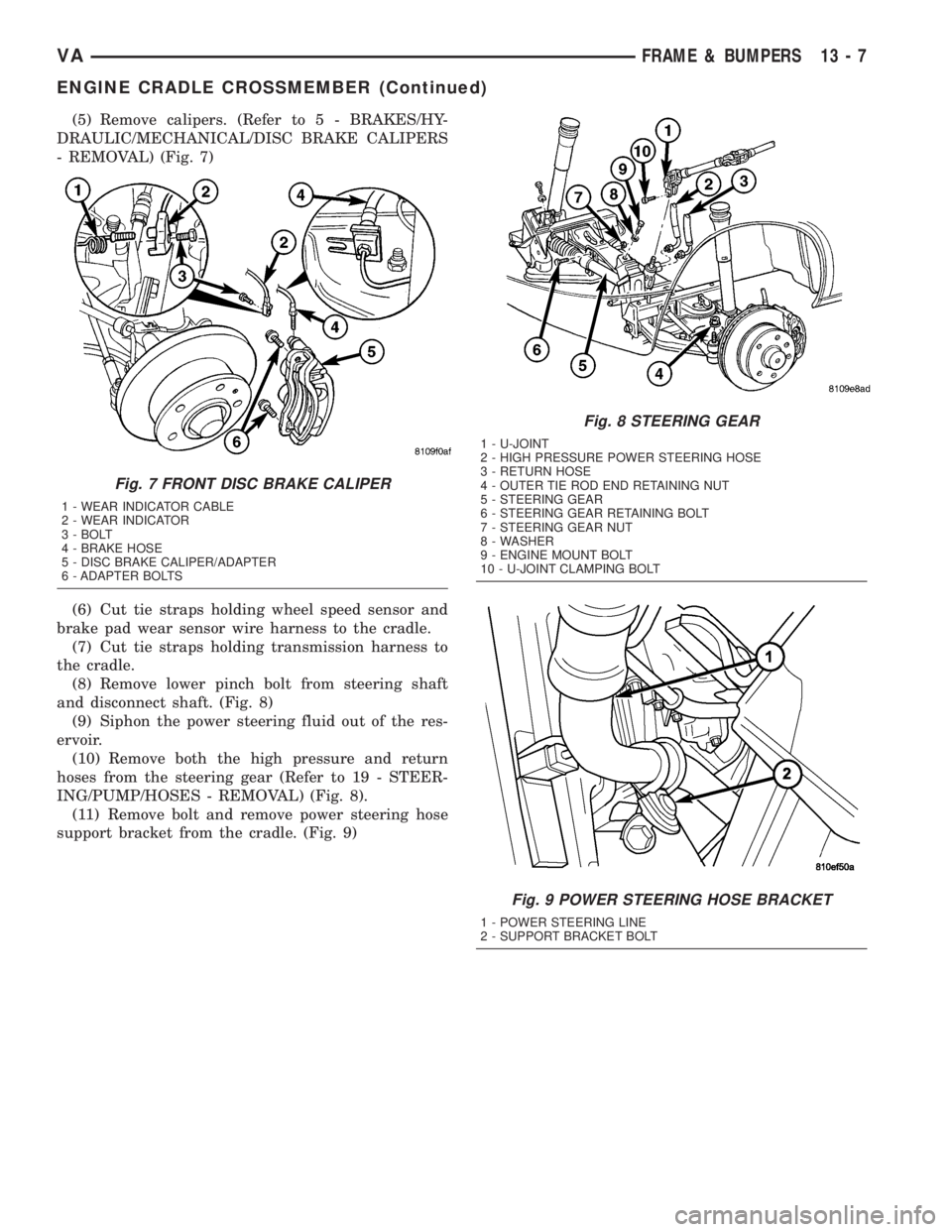
(5) Remove calipers. (Refer to 5 - BRAKES/HY-
DRAULIC/MECHANICAL/DISC BRAKE CALIPERS
- REMOVAL) (Fig. 7)
(6) Cut tie straps holding wheel speed sensor and
brake pad wear sensor wire harness to the cradle.
(7) Cut tie straps holding transmission harness to
the cradle.
(8) Remove lower pinch bolt from steering shaft
and disconnect shaft. (Fig. 8)
(9) Siphon the power steering fluid out of the res-
ervoir.
(10) Remove both the high pressure and return
hoses from the steering gear (Refer to 19 - STEER-
ING/PUMP/HOSES - REMOVAL) (Fig. 8).
(11) Remove bolt and remove power steering hose
support bracket from the cradle. (Fig. 9)
Fig. 7 FRONT DISC BRAKE CALIPER
1 - WEAR INDICATOR CABLE
2 - WEAR INDICATOR
3 - BOLT
4 - BRAKE HOSE
5 - DISC BRAKE CALIPER/ADAPTER
6 - ADAPTER BOLTS
Fig. 8 STEERING GEAR
1 - U-JOINT
2 - HIGH PRESSURE POWER STEERING HOSE
3 - RETURN HOSE
4 - OUTER TIE ROD END RETAINING NUT
5 - STEERING GEAR
6 - STEERING GEAR RETAINING BOLT
7 - STEERING GEAR NUT
8 - WASHER
9 - ENGINE MOUNT BOLT
10 - U-JOINT CLAMPING BOLT
Fig. 9 POWER STEERING HOSE BRACKET
1 - POWER STEERING LINE
2 - SUPPORT BRACKET BOLT
VAFRAME & BUMPERS 13 - 7
ENGINE CRADLE CROSSMEMBER (Continued)