2005 MERCEDES-BENZ SPRINTER Steering wheel
[x] Cancel search: Steering wheelPage 827 of 1232
(3) Tighten steering gear bolts in three stages as
follows.
1. Tighten to 25 N´m (18 ft. lbs.)
2. Then tighten to 45 N´m (33 ft. lbs.)
3. Then tighten bolts an additional 90É.
(4) Install stabilizer bar. (Refer to 2 - SUSPEN-
SION/FRONT/STABILIZER BAR - INSTALLATION)
(5) Install heat shield and nuts.
(6) Install jounce bumpers and install nuts.
(7) Install support clips and brake lines.
(8) Raise engine cradle into place and install bolts.
(9) Tighten bolts to 125 N´m (92 ft. lbs.).
(10) Connect brake lines at couplings and tighten
to 14 N´m (10 ft. lbs.).
(11) Position power steering hose and install sup-
port bracket bolt.
(12) Install both power steering hoses at steering
gear. (Refer to 19 - STEERING/PUMP/HOSES -
INSTALLATION)
(13) Connect steering shaft to gear and install the
lower pinch bolt.
(14) Tighten lower pinch bolt to 24 N´m (18 ft.
lbs.).
(15) Install new tie straps holding transmission
harness to cradle.
(16) Install front spring. (Refer to 2 - SUSPEN-
SION/FRONT/SPRING - INSTALLATION)
(17) Install engine mount nuts and tighten to 45
N´m (33 ft. lbs.).
(18) Install calipers. (Refer to 5 - BRAKES/HY-
DRAULIC/MECHANICAL/DISC BRAKE CALIPERS
- INSTALLATION)
(19) Install new tie straps holding wheel speed
sensors and brake pad wear sensors wire harness to
cradle.
(20) Check and align vehicle to specifications.
(Refer to 2 - SUSPENSION/WHEEL ALIGNMENT -
STANDARD PROCEDURE)
REAR CROSSMEMBER -
TRANSMISSION
REMOVAL
(1) Raise and support the vehicle. (Refer to
LUBRICATION & MAINTENANCE/HOISTING -
STANDARD PROCEDURE)
(2) Support transmission with a suitable lifting
device.
(3) Remove the bolts/nuts and remove transmis-
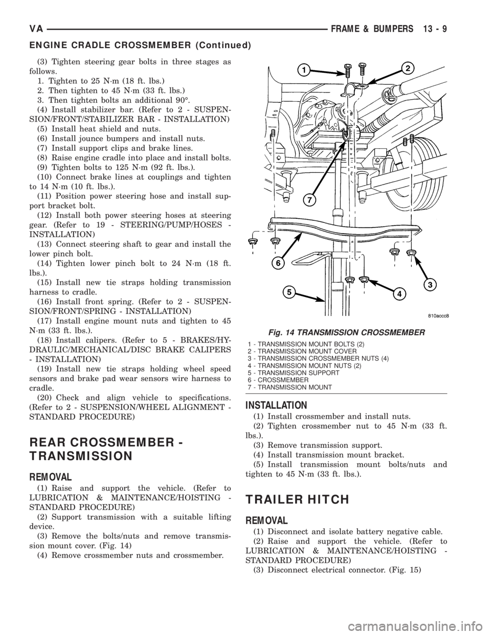
sion mount cover. (Fig. 14)
(4) Remove crossmember nuts and crossmember.
INSTALLATION
(1) Install crossmember and install nuts.
(2) Tighten crossmember nut to 45 N´m (33 ft.
lbs.).
(3) Remove transmission support.
(4) Install transmission mount bracket.
(5) Install transmission mount bolts/nuts and
tighten to 45 N´m (33 ft. lbs.).
TRAILER HITCH
REMOVAL
(1) Disconnect and isolate battery negative cable.
(2) Raise and support the vehicle. (Refer to
LUBRICATION & MAINTENANCE/HOISTING -
STANDARD PROCEDURE)
(3) Disconnect electrical connector. (Fig. 15)
Fig. 14 TRANSMISSION CROSSMEMBER
1 - TRANSMISSION MOUNT BOLTS (2)
2 - TRANSMISSION MOUNT COVER
3 - TRANSMISSION CROSSMEMBER NUTS (4)
4 - TRANSMISSION MOUNT NUTS (2)
5 - TRANSMISSION SUPPORT
6 - CROSSMEMBER
7 - TRANSMISSION MOUNT
VAFRAME & BUMPERS 13 - 9
ENGINE CRADLE CROSSMEMBER (Continued)
Page 861 of 1232
STEERING
TABLE OF CONTENTS
page page
STEERING
DESCRIPTION..........................1
OPERATION............................1
DIAGNOSIS AND TESTING - POWER
STEERING SYSTEM....................2COLUMN...............................5
GEAR..................................8
LINKAGE..............................10
PUMP.................................12
STEERING
DESCRIPTION
CAUTION: Mopar ATF+4 Automatic Transmission
fluid or equivalent is to be used in the power steer-
ing system. No other power steering or automatic
transmission fluid is to be used in the system.
Damage may result to the power steering pump and
system if any other fluid is used, and do not over-
fill.
Power steering systems consist of:
²Steering column
²Rack and pinion steering gear
²Belt driven hydraulic steering pump
²Pump pressure and return hoses
²Oil Cooler
OPERATION
The steering column shaft is attached to the gear
pinion. The rotation of the pinion moves the gear
rack from side-to-side. This lateral action of the rack
pushes and pulls the tie rods to change the direction
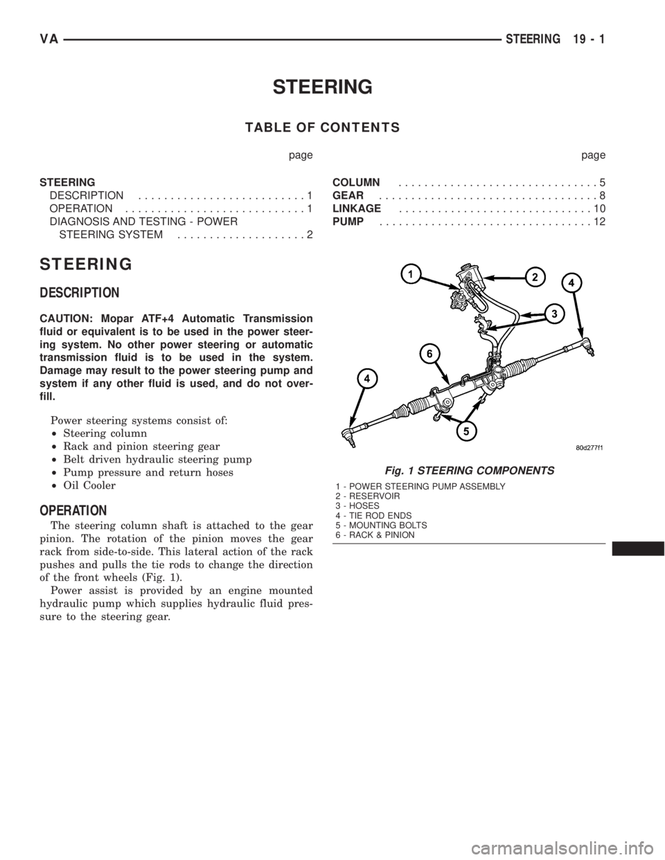
of the front wheels (Fig. 1).
Power assist is provided by an engine mounted
hydraulic pump which supplies hydraulic fluid pres-
sure to the steering gear.
Fig. 1 STEERING COMPONENTS
1 - POWER STEERING PUMP ASSEMBLY
2 - RESERVOIR
3 - HOSES
4 - TIE ROD ENDS
5 - MOUNTING BOLTS
6 - RACK & PINION
VASTEERING 19 - 1
Page 862 of 1232
DIAGNOSIS AND TESTING - POWER STEERING SYSTEM
There is some noise in all power steering systems. One of the most common is a hissing sound evident at a
standstill parking. Or when the steering wheel is at the end of it's travel. Hiss is a high frequency noise similar
to that of a water tap being closed slowly. The noise is present in all valves that have a high velocity fluid passing
through an orifice. There is no relationship between this noise and steering performance.
STEERING NOISE
CONDITION POSSIBLE CAUSES CORRECTION
OBJECTIONAL HISS OR
WHISTLE1. Steering intermediate shaft to dash panel
seal.1. Check and repair seal at dash
panel.
2. Noisy valve in power steering gear. 2. Replace steering gear.
RATTLE OR CLUNK 1. Gear mounting bolts loose. 1. Tighten bolts to specification.
2. Loose or damaged suspension
components.2. Inspect and repair suspension.
3. Internal gear noise. 3. Replace steering gear.
4. Pressure hose in contact with other
components.4. Reposition hose.
5. Loose or damaged intermediate shaft or
column.5. Inspect and repair or replace.
CHIRP OR SQUEAL 1. Loose belt. 1. Adjust or replace.
WHINE OR GROWL 1. Low fluid level. 1. Fill to proper level.
2. Pressure hose in contact with other
components.2. Reposition hose.
3. Internal pump noise. 3. Replace pump.
4. Air in fluid 4. Check for lekas, Evacuate air
from P/S system.
SUCKING AIR SOUND 1. Loose return line clamp. 1. Replace clamp.
2. O-ring missing or damaged on hose
fitting.2. Replace o-ring.
3. Low fluid level. 3. Fill to proper level.
4. Air leak between pump and reservoir. 4. Repair as necessary.
5. Reservoir cap not installed correctly. 5. Install reservoir cap correctly.
SCRUBBING OR
KNOCKING1. Wrong tire size. 1. Verify tire size.
19 - 2 STEERINGVA
STEERING (Continued)
Page 863 of 1232
BINDING AND STICKING
CONDITION POSSIBLE CAUSE CORRECTION
DIFFICULT TO TURN WHEEL
STICKS OR BINDS1. Low fluid level. 1. Fill to proper level.
2. Tire pressure. 2. Adjust tire pressure.
3. Steering components (ball
joints/tie rod ends).3 Inspect and repair as necessary.
4. Loose belt. 4. Adjust or replace.
5. Low pump pressure. 5. Pressure test and replace if
necessary.
6. Column shaft coupler binding. 6. Replace coupler.
7. Steering gear worn. 7. Replace gear.
8. Pump seized / Stuck valve 8. Replace pump.
INSUFFICIENT ASST. OR POOR RETURN TO CENTER
CONDITION POSSIBLE CAUSE CORRECTION
HARD TURNING OR MOMENTARY
INCREASE IN TURNING EFFORT1. Tire pressure. 1. Adjust tire pressure.
2. Low fluid level. 2. Fill to proper level.
3. Loose belt. 3. Adjust or replace.
4. Low pump pressure. 4. Pressure test and repair as
necessary.
5. Internal gear leak. 5. Replace gear.
STEERING WHEEL DOES NOT
WANT TO RETURN TO CENTER
POSITION1. Tire pressure. 1. Adjust tire pressure.
2. Wheel alignment. 2. Align front end.
3. Lack of lubrication. 3. Inspect and lubricate suspension
compnents.
4. High friction in steering gear. 4. Replace gear.
VASTEERING 19 - 3
STEERING (Continued)
Page 864 of 1232
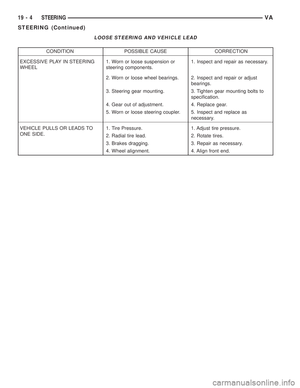
LOOSE STEERING AND VEHICLE LEAD
CONDITION POSSIBLE CAUSE CORRECTION
EXCESSIVE PLAY IN STEERING
WHEEL1. Worn or loose suspension or
steering components.1. Inspect and repair as necessary.
2. Worn or loose wheel bearings. 2. Inspect and repair or adjust
bearings.
3. Steering gear mounting. 3. Tighten gear mounting bolts to
specification.
4. Gear out of adjustment. 4. Replace gear.
5. Worn or loose steering coupler. 5. Inspect and replace as
necessary.
VEHICLE PULLS OR LEADS TO
ONE SIDE.1. Tire Pressure. 1. Adjust tire pressure.
2. Radial tire lead. 2. Rotate tires.
3. Brakes dragging. 3. Repair as necessary.
4. Wheel alignment. 4. Align front end.
19 - 4 STEERINGVA
STEERING (Continued)
Page 865 of 1232
COLUMN
TABLE OF CONTENTS
page page
COLUMN
SPECIFICATIONS - TORQUE CHART.........5
INTERMEDIATE SHAFT
REMOVAL.............................5
INSTALLATION..........................5
KEY/LOCK CYLINDER
REMOVAL.............................6INSTALLATION..........................7
STEERING WHEEL
REMOVAL.............................7
INSTALLATION..........................7
COLUMN
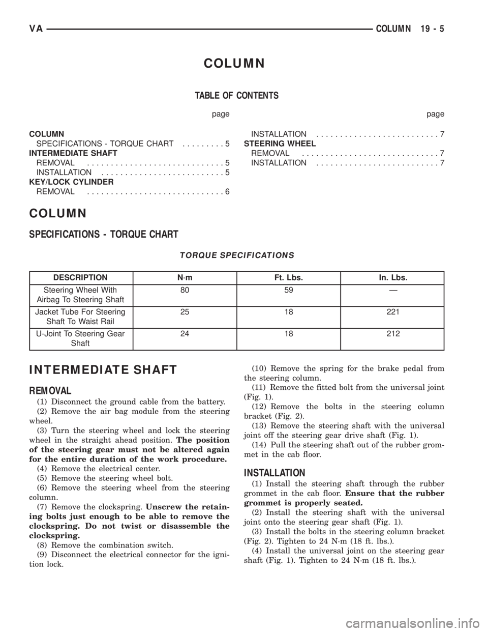
SPECIFICATIONS - TORQUE CHART
TORQUE SPECIFICATIONS
DESCRIPTION N´m Ft. Lbs. In. Lbs.
Steering Wheel With
Airbag To Steering Shaft80 59 Ð
Jacket Tube For Steering
Shaft To Waist Rail25 18 221
U-Joint To Steering Gear
Shaft24 18 212
INTERMEDIATE SHAFT
REMOVAL
(1) Disconnect the ground cable from the battery.
(2) Remove the air bag module from the steering
wheel.
(3) Turn the steering wheel and lock the steering
wheel in the straight ahead position.The position
of the steering gear must not be altered again
for the entire duration of the work procedure.
(4) Remove the electrical center.
(5) Remove the steering wheel bolt.
(6) Remove the steering wheel from the steering
column.
(7) Remove the clockspring.Unscrew the retain-
ing bolts just enough to be able to remove the
clockspring. Do not twist or disassemble the
clockspring.
(8) Remove the combination switch.
(9) Disconnect the electrical connector for the igni-
tion lock.(10) Remove the spring for the brake pedal from
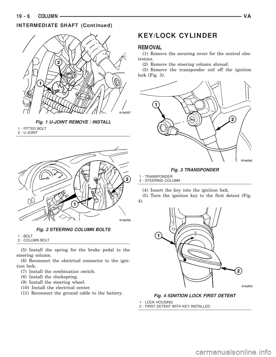
the steering column.
(11) Remove the fitted bolt from the universal joint
(Fig. 1).
(12) Remove the bolts in the steering column
bracket (Fig. 2).
(13) Remove the steering shaft with the universal
joint off the steering gear drive shaft (Fig. 1).
(14) Pull the steering shaft out of the rubber grom-
met in the cab floor.
INSTALLATION
(1) Install the steering shaft through the rubber
grommet in the cab floor.Ensure that the rubber
grommet is properly seated.
(2) Install the steering shaft with the universal
joint onto the steering gear shaft (Fig. 1).
(3) Install the bolts in the steering column bracket
(Fig. 2). Tighten to 24 N´m (18 ft. lbs.).
(4) Install the universal joint on the steering gear
shaft (Fig. 1). Tighten to 24 N´m (18 ft. lbs.).
VACOLUMN 19 - 5
Page 866 of 1232
(5) Install the spring for the brake pedal to the
steering column.
(6) Reconnect the electrical connector to the igni-
tion lock.
(7) Install the combination switch.
(8) Install the clockspring.
(9) Install the steering wheel.
(10) Install the electrical center.
(11) Reconnect the ground cable to the battery.
KEY/LOCK CYLINDER
REMOVAL
(1) Remove the securing cover for the central elec-
tronics.
(2) Remove the steering column shroud.
(3) Remove the transponder coil off the ignition
lock (Fig. 3).
(4) Insert the key into the ignition lock.
(5) Turn the ignition key to the first detent (Fig.
4).
Fig. 1 U-JOINT REMOVE / INSTALL
1 - FITTED BOLT
2 - U-JOINT
Fig. 2 STEERING COLUMN BOLTS
1 - BOLT
2 - COLUMN BOLT
Fig. 3 TRANSPONDER
1 - TRANSPONDER
2 - STEERING COLUMN
Fig. 4 IGNITION LOCK FIRST DETENT
1 - LOCK HOUSING
2 - FIRST DETENT WITH KEY INSTALLED
19 - 6 COLUMNVA
INTERMEDIATE SHAFT (Continued)
Page 867 of 1232
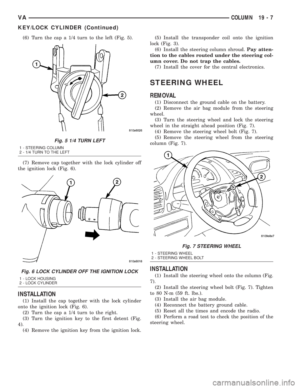
(6) Turn the cap a 1/4 turn to the left (Fig. 5).
(7) Remove cap together with the lock cylinder off
the ignition lock (Fig. 6).
INSTALLATION
(1) Install the cap together with the lock cylinder
onto the ignition lock (Fig. 6).
(2) Turn the cap a 1/4 turn to the right.
(3) Turn the ignition key to the first detent (Fig.
4).
(4) Remove the ignition key from the ignition lock.(5) Install the transponder coil onto the ignition
lock (Fig. 3).
(6) Install the steering column shroud.Pay atten-
tion to the cables routed under the steering col-
umn cover. Do not trap the cables.
(7) Install the cover for the central electronics.
STEERING WHEEL
REMOVAL
(1) Disconnect the ground cable on the battery.
(2) Remove the air bag module from the steering
wheel.
(3) Turn the steering wheel and lock the steering
wheel in the straight ahead position (Fig. 7).
(4) Remove the steering wheel bolt (Fig. 7).
(5) Remove the steering wheel from the steering
column (Fig. 7).
INSTALLATION
(1) Install the steering wheel onto the column (Fig.
7).
(2) Install the steering wheel bolt (Fig. 7). Tighten
to 80 N´m (59 ft. lbs.).
(3) Install the air bag module.
(4) Reconnect the battery ground cable.
(5) Reset all the times and encode the radio.
(6) Perform a road test to check the position of the
steering wheel.
Fig. 5 1/4 TURN LEFT
1 - STEERING COLUMN
2 - 1/4 TURN TO THE LEFT
Fig. 6 LOCK CYLINDER OFF THE IGNITION LOCK
1 - LOCK HOUSING
2 - LOCK CYLINDER
Fig. 7 STEERING WHEEL
1 - STEERING WHEEL
2 - STEERING WHEEL BOLT
VACOLUMN 19 - 7
KEY/LOCK CYLINDER (Continued)