2005 MERCEDES-BENZ SPRINTER Steering wheel
[x] Cancel search: Steering wheelPage 264 of 1232
INSTALLATION
The following procedure is for replacement of a
faulty or damaged passenger airbag. If the airbag is
faulty or damaged, but not deployed, review the rec-
ommended procedures for handling non-deployed
supplemental restraints. (Refer to 8 - ELECTRICAL/
RESTRAINTS - STANDARD PROCEDURE - HAN-
DLING NON-DEPLOYED SUPPLEMENTAL
RESTRAINTS). If the passenger airbag has been
deployed, review the recommended procedures for
service after a supplemental restraint deployment
before removing the airbag from the vehicle. (Refer to
8 - ELECTRICAL/RESTRAINTS - STANDARD PRO-
CEDURE - SERVICE AFTER A SUPPLEMENTAL
RESTRAINT DEPLOYMENT).
WARNING: ON VEHICLES EQUIPPED WITH AIR-
BAGS, DISABLE THE SUPPLEMENTAL RESTRAINT
SYSTEM BEFORE ATTEMPTING ANY STEERING
WHEEL, STEERING COLUMN, DRIVER AIRBAG,
PASSENGER AIRBAG, SEAT BELT TENSIONER, OR
INSTRUMENT PANEL COMPONENT DIAGNOSIS OR
SERVICE. DISCONNECT AND ISOLATE THE BAT-
TERY NEGATIVE (GROUND) CABLE, THEN WAIT
TWO MINUTES FOR THE SYSTEM CAPACITOR TO
DISCHARGE BEFORE PERFORMING FURTHER
DIAGNOSIS OR SERVICE. THIS IS THE ONLY SURE
WAY TO DISABLE THE SUPPLEMENTAL
RESTRAINT SYSTEM. FAILURE TO TAKE THE
PROPER PRECAUTIONS COULD RESULT IN ACCI-
DENTAL AIRBAG DEPLOYMENT AND POSSIBLE
PERSONAL INJURY.
WARNING: WHEN REMOVING A DEPLOYED AIR-
BAG, RUBBER GLOVES, EYE PROTECTION, AND A
LONG-SLEEVED SHIRT SHOULD BE WORN. THERE
MAY BE DEPOSITS ON THE AIRBAG UNIT AND
OTHER INTERIOR SURFACES. IN LARGE DOSES,
THESE DEPOSITS MAY CAUSE IRRITATION TO THE
SKIN AND EYES.
WARNING: USE EXTREME CARE TO PREVENT ANY
FOREIGN MATERIAL FROM ENTERING THE PAS-
SENGER AIRBAG, OR BECOMING ENTRAPPED
BETWEEN THE PASSENGER AIRBAG CUSHION
AND THE PASSENGER AIRBAG DOOR. FAILURE TO
OBSERVE THIS WARNING COULD RESULT IN
OCCUPANT INJURIES UPON AIRBAG DEPLOY-
MENT.WARNING: THE PASSENGER AIRBAG DOOR MUST
NEVER BE PAINTED. REPLACEMENT PASSENGER
AIRBAGS ARE SERVICED WITH DOORS IN THE
ORIGINAL COLORS. PAINT MAY CHANGE THE WAY
IN WHICH THE MATERIAL OF THE AIRBAG DOOR
RESPONDS TO AN AIRBAG DEPLOYMENT. FAIL-
URE TO OBSERVE THIS WARNING COULD RESULT
IN OCCUPANT INJURIES UPON AIRBAG DEPLOY-
MENT.
(1) Carefully position the passenger airbag and
airbag door unit to the instrument panel (Fig. 29).
(2) When installing the passenger airbag, recon-
nect the vehicle wire harness connector to the airbag
inflator connector receptacle by pressing straight in
on the connector. You can be certain that the connec-
tor is fully engaged by listening carefully for a dis-
tinct, audible click as the connector snaps into place.
(3) Push the passenger airbag unit forward far
enough to engage the lower edge of the airbag door
with the two lower clips in the instrument panel.
(4) Install and tighten the two screws that secure
the flange of the passenger airbag housing to the
bracket on the instrument panel structural support.
Tighten the screws to 10 N´m (89 in. lbs.).
(5) Install and tighten the two screws that secure
the passenger airbag door upper clips to the instru-
ment panel base trim. Tighten the screws to 2 N´m
(18 in. lbs.).
(6) Reinstall the instrument panel top cover tray
onto the instrument panel. (Refer to 23 - BODY/IN-
STRUMENT PANEL/INSTRUMENT PANEL TOP
COVER - TRAY - INSTALLATION).
(7) Do not reconnect the battery negative cable at
this time. The supplemental restraint system verifi-
cation test procedure should be performed following
service of any supplemental restraint system compo-
nent. (Refer to 8 - ELECTRICAL/RESTRAINTS -
STANDARD PROCEDURE - VERIFICATION TEST).
8O - 26 RESTRAINTSVA
PASSENGER AIRBAG (Continued)
Page 265 of 1232
PASSENGER AIRBAG
BRACKET
REMOVAL
WARNING: ON VEHICLES EQUIPPED WITH AIR-
BAGS, DISABLE THE SUPPLEMENTAL RESTRAINT
SYSTEM BEFORE ATTEMPTING ANY STEERING
WHEEL, STEERING COLUMN, DRIVER AIRBAG,
PASSENGER AIRBAG, SEAT BELT TENSIONER, OR
INSTRUMENT PANEL COMPONENT DIAGNOSIS OR
SERVICE. DISCONNECT AND ISOLATE THE BAT-
TERY NEGATIVE (GROUND) CABLE, THEN WAIT
TWO MINUTES FOR THE SYSTEM CAPACITOR TO
DISCHARGE BEFORE PERFORMING FURTHER
DIAGNOSIS OR SERVICE. THIS IS THE ONLY SURE
WAY TO DISABLE THE SUPPLEMENTAL
RESTRAINT SYSTEM. FAILURE TO TAKE THE
PROPER PRECAUTIONS COULD RESULT IN ACCI-
DENTAL AIRBAG DEPLOYMENT AND POSSIBLE
PERSONAL INJURY.
(1) Remove the passenger airbag from the instru-
ment panel. (Refer to 8 - ELECTRICAL/RE-
STRAINTS/PASSENGER AIRBAG - REMOVAL).
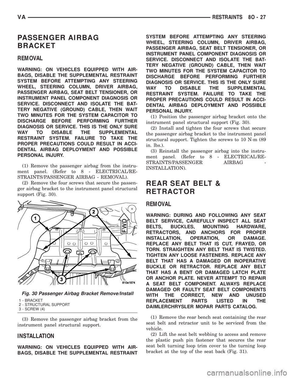
(2) Remove the four screws that secure the passen-
ger airbag bracket to the instrument panel structural
support (Fig. 30).
(3) Remove the passenger airbag bracket from the
instrument panel structural support.
INSTALLATION
WARNING: ON VEHICLES EQUIPPED WITH AIR-
BAGS, DISABLE THE SUPPLEMENTAL RESTRAINTSYSTEM BEFORE ATTEMPTING ANY STEERING
WHEEL, STEERING COLUMN, DRIVER AIRBAG,
PASSENGER AIRBAG, SEAT BELT TENSIONER, OR
INSTRUMENT PANEL COMPONENT DIAGNOSIS OR
SERVICE. DISCONNECT AND ISOLATE THE BAT-
TERY NEGATIVE (GROUND) CABLE, THEN WAIT
TWO MINUTES FOR THE SYSTEM CAPACITOR TO
DISCHARGE BEFORE PERFORMING FURTHER
DIAGNOSIS OR SERVICE. THIS IS THE ONLY SURE
WAY TO DISABLE THE SUPPLEMENTAL
RESTRAINT SYSTEM. FAILURE TO TAKE THE
PROPER PRECAUTIONS COULD RESULT IN ACCI-
DENTAL AIRBAG DEPLOYMENT AND POSSIBLE
PERSONAL INJURY.
(1) Position the passenger airbag bracket onto the
instrument panel structural support (Fig. 30).
(2) Install and tighten the four screws that secure
the passenger airbag bracket to the instrument panel
structural support. Tighten the screws to 10 N´m (89
in. lbs.).
(3) Reinstall the passenger airbag into the instru-
ment panel. (Refer to 8 - ELECTRICAL/RE-
STRAINTS/PASSENGER AIRBAG -
INSTALLATION).
REAR SEAT BELT &
RETRACTOR
REMOVAL
WARNING: DURING AND FOLLOWING ANY SEAT
BELT SERVICE, CAREFULLY INSPECT ALL SEAT
BELTS, BUCKLES, MOUNTING HARDWARE,
RETRACTORS, AND ANCHORS FOR PROPER
INSTALLATION, OPERATION, OR DAMAGE.
REPLACE ANY BELT THAT IS CUT, FRAYED, OR
TORN. STRAIGHTEN ANY BELT THAT IS TWISTED.
TIGHTEN ANY LOOSE FASTENERS. REPLACE ANY
BELT THAT HAS A DAMAGED OR INOPERATIVE
BUCKLE OR RETRACTOR. REPLACE ANY BELT
THAT HAS A BENT OR DAMAGED LATCH PLATE
OR ANCHOR PLATE. NEVER ATTEMPT TO REPAIR
A SEAT BELT COMPONENT. ALWAYS REPLACE
DAMAGED OR FAULTY SEAT BELT COMPONENTS
WITH THE CORRECT, NEW AND UNUSED
REPLACEMENT PARTS LISTED IN THE
DAIMLERCHRYSLER MOPAR PARTS CATALOG.
(1) Remove the rear bench seat containing the rear
seat belt and retractor unit to be serviced from the
vehicle.
(2) Lift the seat belt webbing to access and remove
the plastic push pin fastener that secures the rear
seat belt turning loop trim cover to the turning loop
bracket at the top of the seat back (Fig. 31).
Fig. 30 Passenger Airbag Bracket Remove/Install
1 - BRACKET
2 - STRUCTURAL SUPPORT
3 - SCREW (4)
VARESTRAINTS 8O - 27
Page 270 of 1232
lar steel housing, a piston, a cable, a torsion bar, and
a small pyrotechnically activated gas generator. All of
these components are located on one side of the
retractor spool on the outside of the retractor housing
except for the torsion bar, which serves as the spin-
dle upon which the retractor spool rotates. The seat
belt tensioner is controlled by the Airbag Control
Module (ACM) and is connected to the vehicle elec-
trical system through a dedicated take out of the
vehicle wire harness by a keyed, snap-fit molded
plastic connector insulator to ensure a secure connec-
tion.
The seat belt tensioner cannot be repaired and, if
faulty or damaged, the entire front seat belt and
retractor unit must be replaced. If the front airbags
have been deployed, the seat belt tensioners have
also been deployed. The seat belt tensioner is not
intended for reuse and must be replaced following a
deployment. A growling or grinding sound while
attempting to operate the seat belt retractor is a sure
indication that the seat belt tensioner has been
deployed and requires replacement. (Refer to 8 -
ELECTRICAL/RESTRAINTS/FRONT SEAT BELT &
RETRACTOR - REMOVAL).
OPERATION
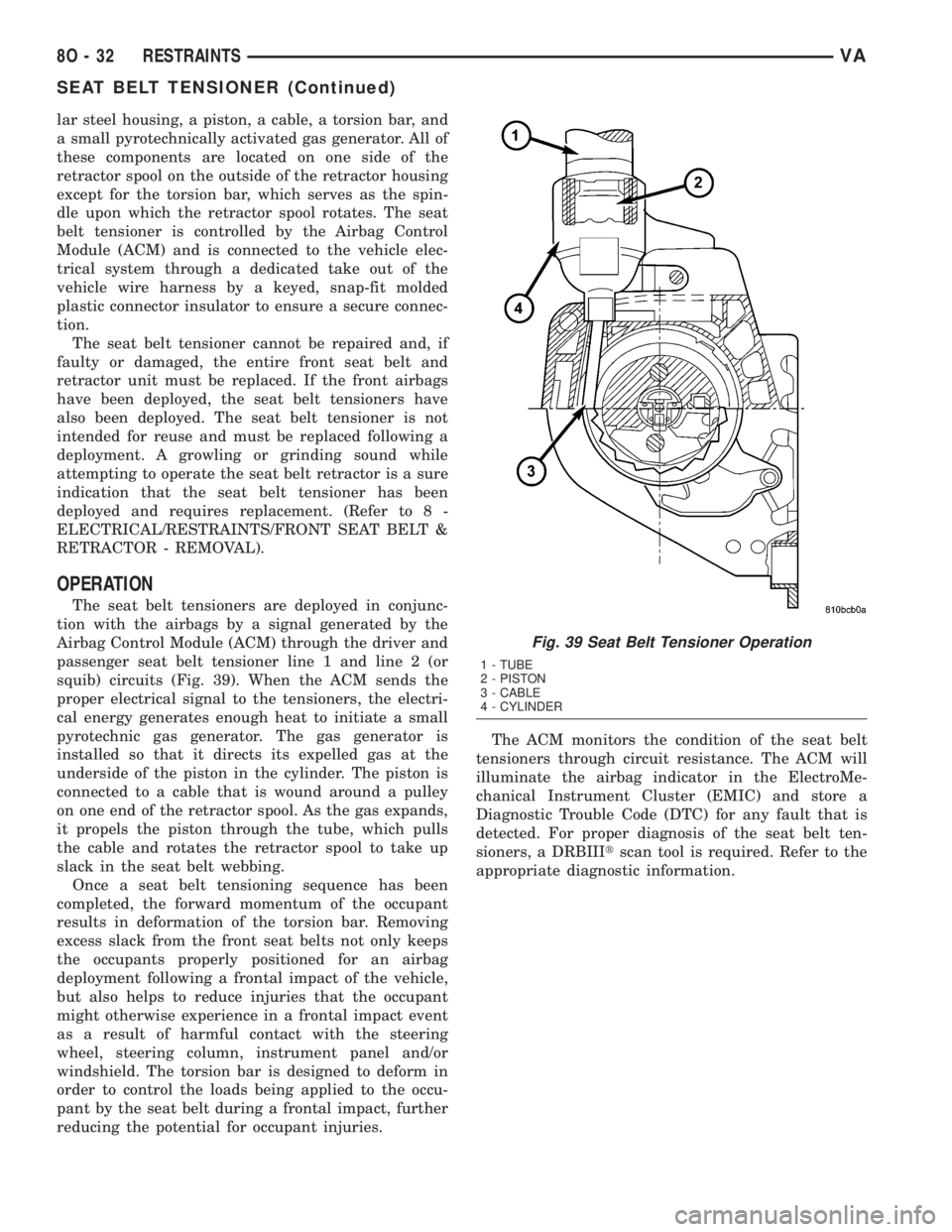
The seat belt tensioners are deployed in conjunc-
tion with the airbags by a signal generated by the
Airbag Control Module (ACM) through the driver and
passenger seat belt tensioner line 1 and line 2 (or
squib) circuits (Fig. 39). When the ACM sends the
proper electrical signal to the tensioners, the electri-
cal energy generates enough heat to initiate a small
pyrotechnic gas generator. The gas generator is
installed so that it directs its expelled gas at the
underside of the piston in the cylinder. The piston is
connected to a cable that is wound around a pulley
on one end of the retractor spool. As the gas expands,
it propels the piston through the tube, which pulls
the cable and rotates the retractor spool to take up
slack in the seat belt webbing.
Once a seat belt tensioning sequence has been
completed, the forward momentum of the occupant
results in deformation of the torsion bar. Removing
excess slack from the front seat belts not only keeps
the occupants properly positioned for an airbag
deployment following a frontal impact of the vehicle,
but also helps to reduce injuries that the occupant
might otherwise experience in a frontal impact event
as a result of harmful contact with the steering
wheel, steering column, instrument panel and/or
windshield. The torsion bar is designed to deform in
order to control the loads being applied to the occu-
pant by the seat belt during a frontal impact, further
reducing the potential for occupant injuries.The ACM monitors the condition of the seat belt
tensioners through circuit resistance. The ACM will
illuminate the airbag indicator in the ElectroMe-
chanical Instrument Cluster (EMIC) and store a
Diagnostic Trouble Code (DTC) for any fault that is
detected. For proper diagnosis of the seat belt ten-
sioners, a DRBIIItscan tool is required. Refer to the
appropriate diagnostic information.
Fig. 39 Seat Belt Tensioner Operation
1 - TUBE
2 - PISTON
3 - CABLE
4 - CYLINDER
8O - 32 RESTRAINTSVA
SEAT BELT TENSIONER (Continued)
Page 271 of 1232
SEAT BELT TURNING LOOP
ADJUSTER
REMOVAL
WARNING: ON VEHICLES EQUIPPED WITH AIR-
BAGS, DISABLE THE SUPPLEMENTAL RESTRAINT
SYSTEM BEFORE ATTEMPTING ANY STEERING
WHEEL, STEERING COLUMN, DRIVER AIRBAG,
PASSENGER AIRBAG, SEAT BELT TENSIONER, OR
INSTRUMENT PANEL COMPONENT DIAGNOSIS OR
SERVICE. DISCONNECT AND ISOLATE THE BAT-
TERY NEGATIVE (GROUND) CABLE, THEN WAIT
TWO MINUTES FOR THE SYSTEM CAPACITOR TO
DISCHARGE BEFORE PERFORMING FURTHER
DIAGNOSIS OR SERVICE. THIS IS THE ONLY SURE
WAY TO DISABLE THE SUPPLEMENTAL
RESTRAINT SYSTEM. FAILURE TO TAKE THE
PROPER PRECAUTIONS COULD RESULT IN ACCI-
DENTAL AIRBAG DEPLOYMENT AND POSSIBLE
PERSONAL INJURY.
WARNING: DURING AND FOLLOWING ANY SEAT
BELT SERVICE, CAREFULLY INSPECT ALL SEAT
BELTS, BUCKLES, MOUNTING HARDWARE,
RETRACTORS, AND ANCHORS FOR PROPER
INSTALLATION, OPERATION, OR DAMAGE.
REPLACE ANY BELT THAT IS CUT, FRAYED, OR
TORN. STRAIGHTEN ANY BELT THAT IS TWISTED.
TIGHTEN ANY LOOSE FASTENERS. REPLACE ANY
BELT THAT HAS A DAMAGED OR INOPERATIVE
BUCKLE OR RETRACTOR. REPLACE ANY BELT
THAT HAS A BENT OR DAMAGED LATCH PLATE
OR ANCHOR PLATE. NEVER ATTEMPT TO REPAIR
A SEAT BELT COMPONENT. ALWAYS REPLACE
DAMAGED OR FAULTY SEAT BELT COMPONENTS
WITH THE CORRECT, NEW AND UNUSED
REPLACEMENT PARTS LISTED IN THE
DAIMLERCHRYSLER MOPAR PARTS CATALOG.
(1) Move the front seat to its most forward position
for easiest access to the B-pillar trim.
(2) Disconnect and isolate the battery negative
cable. Wait two minutes for the system capacitor to
discharge before further service.
(3) Remove the trim panel from the inside of the
B-pillar. (Refer to 23 - BODY/INTERIOR/B-PILLAR
TRIM - REMOVAL).
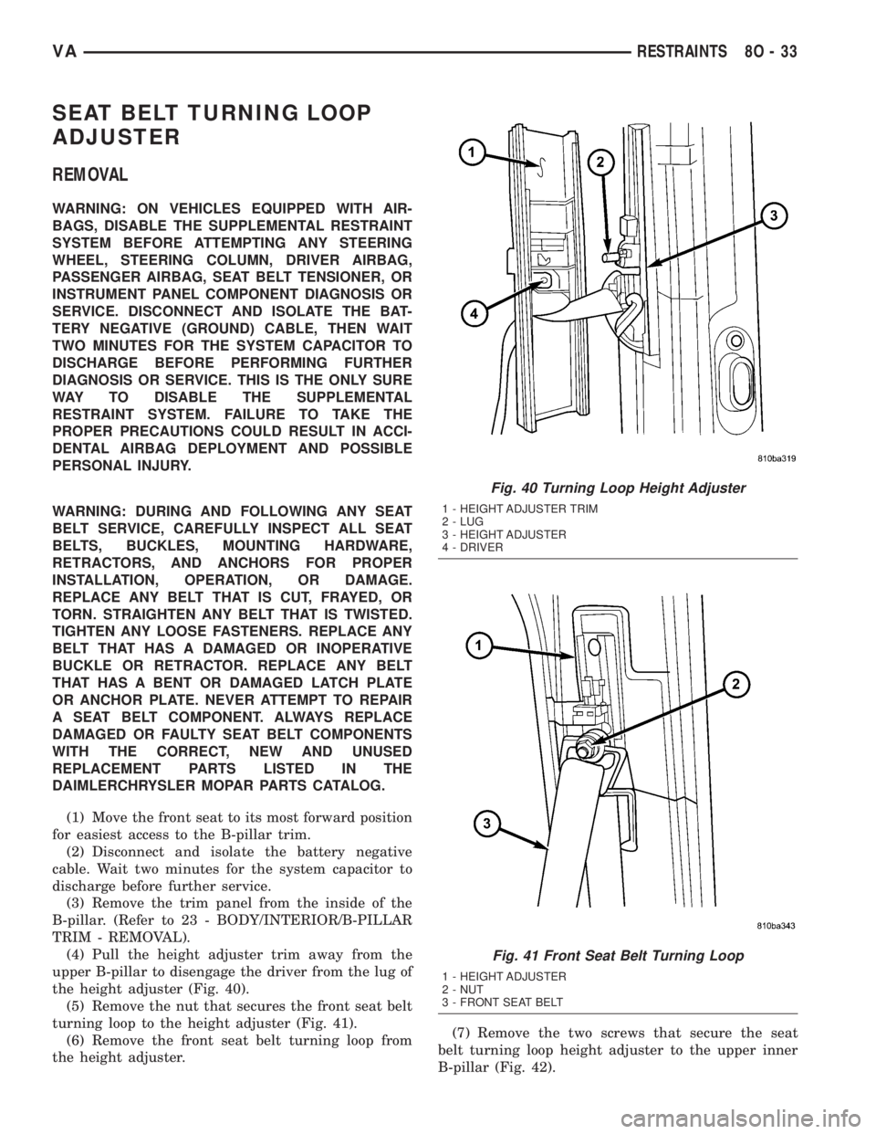
(4) Pull the height adjuster trim away from the
upper B-pillar to disengage the driver from the lug of
the height adjuster (Fig. 40).
(5) Remove the nut that secures the front seat belt
turning loop to the height adjuster (Fig. 41).
(6) Remove the front seat belt turning loop from
the height adjuster.(7) Remove the two screws that secure the seat
belt turning loop height adjuster to the upper inner
B-pillar (Fig. 42).
Fig. 40 Turning Loop Height Adjuster
1 - HEIGHT ADJUSTER TRIM
2 - LUG
3 - HEIGHT ADJUSTER
4 - DRIVER
Fig. 41 Front Seat Belt Turning Loop
1 - HEIGHT ADJUSTER
2 - NUT
3 - FRONT SEAT BELT
VARESTRAINTS 8O - 33
Page 272 of 1232
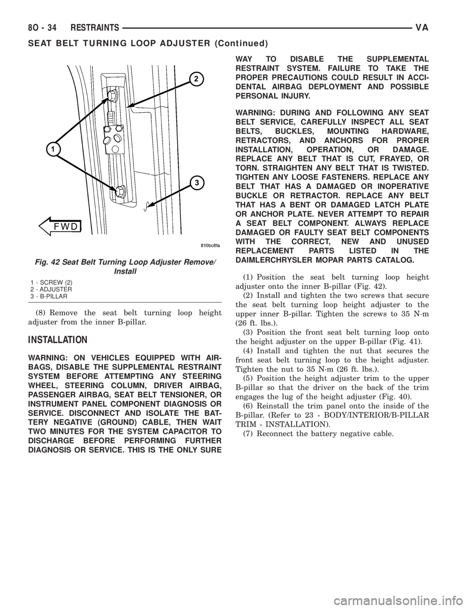
(8) Remove the seat belt turning loop height
adjuster from the inner B-pillar.
INSTALLATION
WARNING: ON VEHICLES EQUIPPED WITH AIR-
BAGS, DISABLE THE SUPPLEMENTAL RESTRAINT
SYSTEM BEFORE ATTEMPTING ANY STEERING
WHEEL, STEERING COLUMN, DRIVER AIRBAG,
PASSENGER AIRBAG, SEAT BELT TENSIONER, OR
INSTRUMENT PANEL COMPONENT DIAGNOSIS OR
SERVICE. DISCONNECT AND ISOLATE THE BAT-
TERY NEGATIVE (GROUND) CABLE, THEN WAIT
TWO MINUTES FOR THE SYSTEM CAPACITOR TO
DISCHARGE BEFORE PERFORMING FURTHER
DIAGNOSIS OR SERVICE. THIS IS THE ONLY SUREWAY TO DISABLE THE SUPPLEMENTAL
RESTRAINT SYSTEM. FAILURE TO TAKE THE
PROPER PRECAUTIONS COULD RESULT IN ACCI-
DENTAL AIRBAG DEPLOYMENT AND POSSIBLE
PERSONAL INJURY.
WARNING: DURING AND FOLLOWING ANY SEAT
BELT SERVICE, CAREFULLY INSPECT ALL SEAT
BELTS, BUCKLES, MOUNTING HARDWARE,
RETRACTORS, AND ANCHORS FOR PROPER
INSTALLATION, OPERATION, OR DAMAGE.
REPLACE ANY BELT THAT IS CUT, FRAYED, OR
TORN. STRAIGHTEN ANY BELT THAT IS TWISTED.
TIGHTEN ANY LOOSE FASTENERS. REPLACE ANY
BELT THAT HAS A DAMAGED OR INOPERATIVE
BUCKLE OR RETRACTOR. REPLACE ANY BELT
THAT HAS A BENT OR DAMAGED LATCH PLATE
OR ANCHOR PLATE. NEVER ATTEMPT TO REPAIR
A SEAT BELT COMPONENT. ALWAYS REPLACE
DAMAGED OR FAULTY SEAT BELT COMPONENTS
WITH THE CORRECT, NEW AND UNUSED
REPLACEMENT PARTS LISTED IN THE
DAIMLERCHRYSLER MOPAR PARTS CATALOG.
(1) Position the seat belt turning loop height
adjuster onto the inner B-pillar (Fig. 42).
(2) Install and tighten the two screws that secure
the seat belt turning loop height adjuster to the
upper inner B-pillar. Tighten the screws to 35 N´m
(26 ft. lbs.).
(3) Position the front seat belt turning loop onto
the height adjuster on the upper B-pillar (Fig. 41).
(4) Install and tighten the nut that secures the
front seat belt turning loop to the height adjuster.
Tighten the nut to 35 N´m (26 ft. lbs.).
(5) Position the height adjuster trim to the upper
B-pillar so that the driver on the back of the trim
engages the lug of the height adjuster (Fig. 40).
(6) Reinstall the trim panel onto the inside of the
B-pillar. (Refer to 23 - BODY/INTERIOR/B-PILLAR
TRIM - INSTALLATION).
(7) Reconnect the battery negative cable.
Fig. 42 Seat Belt Turning Loop Adjuster Remove/
Install
1 - SCREW (2)
2 - ADJUSTER
3 - B-PILLAR
8O - 34 RESTRAINTSVA
SEAT BELT TURNING LOOP ADJUSTER (Continued)
Page 273 of 1232
SPEED CONTROL
TABLE OF CONTENTS
page page
SPEED CONTROL
DESCRIPTION..........................1
OPERATION............................1
SPECIFICATIONS
TORQUE.............................2
CABLE
DESCRIPTION..........................3SERVO
DESCRIPTION..........................3
SWITCH
REMOVAL.............................3
INSTALLATION..........................3
SPEED CONTROL
DESCRIPTION
The speed control system is electronically con-
trolled by the Engine Control Module (ECM).A
cable and a vacuum controlled servo are not
used. This is a servo-less system.Control of the
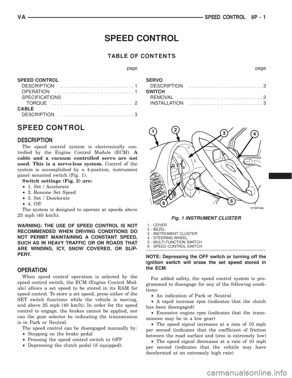
system is accomplished by a 4-position, instrument
panel mounted switch (Fig. 1).
Switch settings (Fig. 2) are:
²1. Set / Accelerate
²2. Resume Set Speed
²3. Set / Decelerate
²4. Off
The system is designed to operate at speeds above
25 mph (40 km/h).
WARNING: THE USE OF SPEED CONTROL IS NOT
RECOMMENDED WHEN DRIVING CONDITIONS DO
NOT PERMIT MAINTAINING A CONSTANT SPEED,
SUCH AS IN HEAVY TRAFFIC OR ON ROADS THAT
ARE WINDING, ICY, SNOW COVERED, OR SLIP-
PERY.
OPERATION
When speed control operation is selected by the
speed control switch, the ECM (Engine Control Mod-
ule) allows a set speed to be stored in its RAM for
speed control. To store a set speed, press either of the
SET switch functions while the vehicle is moving,
and above 25 mph (40 km/h). In order for the speed
control to engage, the brakes cannot be applied, nor
can the gear selector be indicating the transmission
is in Park or Neutral.
The speed control can be disengaged manually by:
²Stepping on the brake pedal
²Pressing the speed control switch to OFF
²Depressing the clutch pedal (if equipped).NOTE: Depressing the OFF switch or turning off the
ignition switch will erase the set speed stored in
the ECM.
For added safety, the speed control system is pro-
grammed to disengage for any of the following condi-
tions:
²An indication of Park or Neutral
²A rapid increase rpm (indicates that the clutch
has been disengaged)
²Excessive engine rpm (indicates that the trans-
mission may be in a low gear)
²The speed signal increases at a rate of 10 mph
per second (indicates that the coefficient of friction
between the road surface and tires is extremely low)
²The speed signal decreases at a rate of 10 mph
per second (indicates that the vehicle may have
decelerated at an extremely high rate)
Fig. 1 INSTRUMENT CLUSTER
1 - COVER
2 - BEZEL
3 - INSTRUMENT CLUSTER
4 - STEERING WHEEL
5 - MULTI-FUNCTION SWITCH
6 - SPEED CONTROL SWITCH
VASPEED CONTROL 8P - 1
Page 283 of 1232
WIPERS/WASHERS
TABLE OF CONTENTS
page page
WIPERS/WASHERS
DESCRIPTION..........................1
OPERATION............................3
DIAGNOSIS AND TESTING - WIPER &
WASHER SYSTEM.....................5
CLEANING - WIPER & WASHER SYSTEM.....5
INSPECTION - WIPER & WASHER SYSTEM . . . 6
CHECK VALVE
DESCRIPTION..........................7
OPERATION............................7
REMOVAL.............................7
INSTALLATION..........................7
WASHER FLUID LEVEL SWITCH
DESCRIPTION..........................7
OPERATION............................8
WASHER HOSES/TUBES
DESCRIPTION..........................8
OPERATION............................9
WASHER NOZZLE
DESCRIPTION..........................9
OPERATION............................9
REMOVAL.............................9
INSTALLATION..........................9
WASHER PUMP/MOTOR
DESCRIPTION..........................9
OPERATION...........................10
REMOVAL.............................10
INSTALLATION.........................10
WASHER RESERVOIR
DESCRIPTION.........................11OPERATION...........................11
REMOVAL.............................11
INSTALLATION.........................12
WIPER ARM
DESCRIPTION.........................13
OPERATION...........................14
REMOVAL.............................14
INSTALLATION.........................14
WIPER BLADE
DESCRIPTION.........................15
OPERATION...........................15
REMOVAL.............................16
INSTALLATION.........................16
WIPER LINKAGE
DESCRIPTION.........................17
OPERATION...........................17
REMOVAL.............................17
INSTALLATION.........................18
WIPER MOTOR
DESCRIPTION.........................19
OPERATION...........................19
REMOVAL.............................19
INSTALLATION.........................19
WIPER RELAY
DESCRIPTION.........................20
OPERATION...........................21
REMOVAL.............................22
INSTALLATION.........................22
WIPERS/WASHERS
DESCRIPTION
An electrically operated intermittent wiper and
washer system is standard factory-installed safety
equipment on this model (Fig. 1). The wiper and
washer system includes the following major compo-
nents, which are described in further detail else-
where in this service information:
²Check Valve- The washer system check valve
is integral to the plumbing fitting located in the
washer plumbing between the cowl plenum washer
hose and the two washer nozzle hoses, and is located
beneath the cowl top panel at the base of the wind-
shield in the engine compartment.
²Multi-Function Switch- The multi-function
switch is secured to the top of the steering column,just below the steering wheel. Only the left (lighting),
right (wiper) control stalks and the hazard warning
switch button for the multi-function switch are visi-
ble, the remainder of the switch is concealed beneath
the steering column shrouds. The multi-function
switch contains all of the switches for both the wiper
and washer systems.(Refer to 8 - ELECTRICAL/
LAMPS/LIGHTING - EXTERIOR/MULTI-FUNC-
TION SWITCH - DESCRIPTION)
²Washer Fluid Level Switch- The optional
washer fluid level switch is integral to a unique ver-
sion of the washer pump/motor unit, which is located
in a dedicated hole on the top of the sump area near
the back of the windshield washer reservoir on the
right front fender wheel house in the engine com-
partment.
²Washer Nozzle- A single washer nozzle with
three separate orifices is secured with integral snap
VAWIPERS/WASHERS 8R - 1
Page 286 of 1232
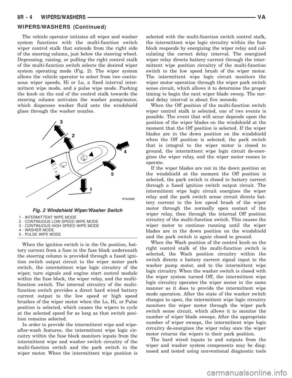
The vehicle operator initiates all wiper and washer
system functions with the multi-function switch
wiper control stalk that extends from the right side
of the steering column, just below the steering wheel.
Depressing, raising, or pulling the right control stalk
of the multi-function switch selects the desired wiper
system operating mode (Fig. 2). The wiper system
allows the vehicle operator to select from two contin-
uous wiper speeds, Hi or Lo, a fixed interval inter-
mittent wipe mode, and a pulse wipe mode. Pushing
the knob on the end of the control stalk towards the
steering column activates the washer pump/motor,
which dispenses washer fluid onto the windshield
glass through the washer nozzles.
When the ignition switch is in the On position, bat-
tery current from a fuse in the fuse block underneath
the steering column is provided through a fused igni-
tion switch output circuit to the wiper motor park
switch, the intermittent wipe logic circuitry of the
wiper, turn signals and engine start control module
within the fuse block, the wiper relay, and the multi-
function switch. The internal circuitry of the multi-
function switch provides a direct hard wired battery
current output to the low speed or high speed
brushes of the wiper motor when the Lo, Hi, or Pulse
position is selected, which causes the wipers to cycle
at the selected speed for as long as that switch posi-
tion remains selected.
In order to provide the intermittent wipe and wipe-
after-wash features, the intermittent wipe logic cir-
cuitry within the fuse block monitors inputs from the
intermittent wipe and washer switch circuitry of the
multi-function switch and the park switch in the
wiper motor. When the intermittent wipe position isselected with the multi-function switch control stalk,
the intermittent wipe logic circuitry within the fuse
block responds by energizing the wiper relay and cal-
culating the correct delay interval. The energized
wiper relay directs battery current through the inter-
mittent wipe position circuitry of the multi-function
switch to the low speed brush of the wiper motor.
The intermittent wipe logic circuit monitors the
wiper motor operation through the wiper park switch
sense circuit, which allows it to determine the proper
timing to begin the next wiper blade sweep. The nor-
mal delay interval is about five seconds.
When the Off position of the multi-function switch
wiper control stalk is selected, one of two events is
possible. The event that will occur depends upon the
position of the wiper blades on the windshield at the
moment that the Off position is selected. If the wiper
blades are in the down position on the windshield
when the Off position is selected, the park switch
that is integral to the wiper motor is closed to
ground, the intermittent wipe logic circuit de-ener-
gizes the wiper relay, and the wiper motor ceases to
operate.
If the wiper blades are not in the down position on
the windshield at the moment the Off position is
selected, the park switch is closed to battery current
through a fused ignition switch output circuit. The
intermittent wipe logic circuit energizes the wiper
relay and the park switch sense circuit directs bat-
tery current to the low speed brush of the wiper
motor through the normally open contact of the
wiper relay, then through the internal Off position
circuitry of the multi-function switch. This causes the
wiper motor to continue running until the wiper
blades are in the down position on the windshield
and the park switch is again closed to ground.
When the Wash position of the control knob on the
right control stalk of the multi-function switch is
selected, the Wash position circuitry within the
switch directs a battery current signal input to the
washer pump motor, and to the intermittent wipe
logic circuitry. When the washer switch is closed with
the wiper system turned Off, the intermittent wipe
logic circuitry operates the wiper motor in the same
manner as it does to provide the intermittent wipe
mode operation. After the state of the washer switch
changes to open, the intermittent wipe logic circuitry
monitors the wiper motor through the wiper park
switch sense circuit, which allows it to monitor the
number of wiper blade sweeps. After the appropriate
number of wiper sweeps, the intermittent wipe logic
circuitry de-energizes the wiper relay once the wiper
motor returns the wipers to their park position.
The hard wired inputs to and outputs from the
wiper and washer system components may be diag-
nosed and tested using conventional diagnostic tools
Fig. 2 Windshield Wiper/Washer Switch
1 - INTERMITTENT WIPE MODE
2 - CONTINUOUS LOW SPEED WIPE MODE
3 - CONTINUOUS HIGH SPEED WIPE MODE
4 - WASHER MODE
5 - PULSE WIPE MODE
8R - 4 WIPERS/WASHERSVA
WIPERS/WASHERS (Continued)