2005 MERCEDES-BENZ SPRINTER wheel
[x] Cancel search: wheelPage 1030 of 1232
TIRES
DESCRIPTION
DESCRIPTION - TIRES
Tires are designed and engineered for each specific
vehicle. They provide the best overall performance
for normal operation. The ride and handling charac-
teristics match the vehicle's requirements. With
proper care they will give excellent reliability, trac-
tion, skid resistance, and tread life.
Driving habits have more effect on tire life than
any other factor. Careful drivers will obtain in most
cases, much greater mileage than severe use or care-
less drivers. A few of the driving habits which will
shorten the life of any tire are:
²Rapid acceleration
²Severe brake applications
²High speed driving
²Excessive speeds on turns
²Striking curbs and other obstacles
Radial-ply tires are more prone to irregular tread
wear. It is important to follow the tire rotation inter-
val shown in the section on Tire Rotation, (Refer to
22 - TIRES/WHEELS - STANDARD PROCEDURE).
This will help to achieve a greater tread life.
TIRE IDENTIFICATION
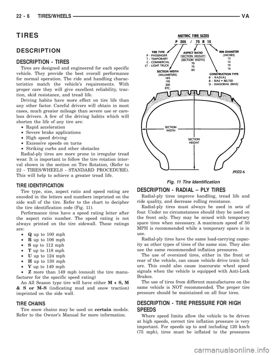
Tire type, size, aspect ratio and speed rating are
encoded in the letters and numbers imprinted on the
side wall of the tire. Refer to the chart to decipher
the tire identification code (Fig. 11).
Performance tires have a speed rating letter after
the aspect ratio number. The speed rating is not
always printed on the tire sidewall. These ratings
are:
²Qup to 100 mph
²Rup to 106 mph
²Sup to 112 mph
²Tup to 118 mph
²Uup to 124 mph
²Hup to 130 mph
²Vup to 149 mph
²Zmore than 149 mph (consult the tire manu-
facturer for the specific speed rating)
An All Season type tire will have eitherM+S,M
&SorM±S(indicating mud and snow traction)
imprinted on the side wall.
TIRE CHAINS
Tire snow chains may be used oncertainmodels.
Refer to the Owner's Manual for more information.
DESCRIPTION - RADIAL ± PLY TIRES
Radial-ply tires improve handling, tread life and
ride quality, and decrease rolling resistance.
Radial-ply tires must always be used in sets of
four. Under no circumstances should they be used on
the front only. They may be mixed with temporary
spare tires when necessary. A maximum speed of 50
MPH is recommended while a temporary spare is in
use.
Radial-ply tires have the same load-carrying capac-
ity as other types of tires of the same size. They also
use the same recommended inflation pressures.
The use of oversized tires, either in the front or
rear of the vehicle, can cause vehicle drive train fail-
ure. This could also cause inaccurate wheel speed
signals when the vehicle is equipped with Anti-Lock
Brakes.
The use of tires from different manufactures on the
same vehicle is NOT recommended. The proper tire
pressure should be maintained on all four tires.
DESCRIPTION - TIRE PRESSURE FOR HIGH
SPEEDS
Where speed limits allow the vehicle to be driven
at high speeds, correct tire inflation pressure is very
important. For speeds up to and including 120 km/h
(75 mph), tires must be inflated to the pressures
Fig. 11 Tire Identification
22 - 6 TIRES/WHEELSVA
Page 1031 of 1232
shown on the tire placard. For continuous speeds in
excess of 120 km/h (75 mph), tires must be inflated
to the maximum pressure specified on the tire side-
wall.
Vehicles loaded to the maximum capacity should
not be driven at continuous speeds above 75 mph
(120 km/h).
For emergency vehicles that are driven at speeds
over 90 mph (144 km/h), special high speed tires
must be used. Consult tire manufacturer for correct
inflation pressure recommendations.
DESCRIPTION - REPLACEMENT TIRES
The original equipment tires provide a proper bal-
ance of many characteristics such as:
²Ride
²Noise
²Handling
²Durability
²Tread life
²Traction
²Rolling resistance
²Speed capability
It is recommended that tires equivalent to the orig-
inal equipment tires be used when replacement is
needed.
Failure to use equivalent replacement tires may
adversely affect the safety and handling of the vehi-
cle.
The use of oversize tires may cause interference
with vehicle components. Under extremes of suspen-
sion and steering travel, interference with vehicle
components may cause tire damage.
WARNING: FAILURE TO EQUIP THE VEHICLE WITH
TIRES HAVING ADEQUATE SPEED CAPABILITY
CAN RESULT IN SUDDEN TIRE FAILURE.
DESCRIPTION - TIRE INFLATION PRESSURES
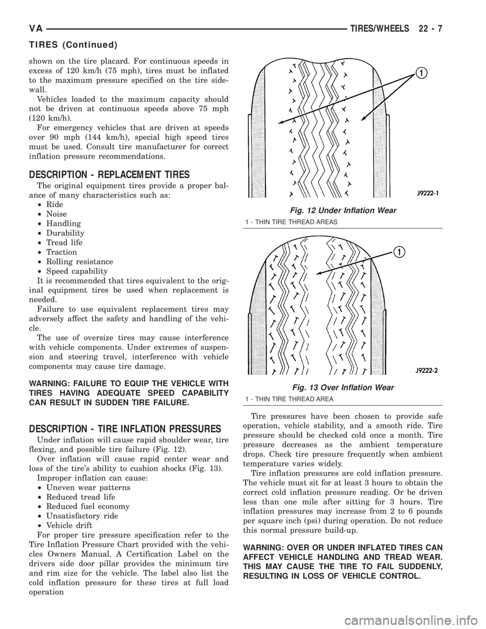
Under inflation will cause rapid shoulder wear, tire
flexing, and possible tire failure (Fig. 12).
Over inflation will cause rapid center wear and
loss of the tire's ability to cushion shocks (Fig. 13).
Improper inflation can cause:
²Uneven wear patterns
²Reduced tread life
²Reduced fuel economy
²Unsatisfactory ride
²Vehicle drift
For proper tire pressure specification refer to the
Tire Inflation Pressure Chart provided with the vehi-
cles Owners Manual. A Certification Label on the
drivers side door pillar provides the minimum tire
and rim size for the vehicle. The label also list the
cold inflation pressure for these tires at full load
operationTire pressures have been chosen to provide safe
operation, vehicle stability, and a smooth ride. Tire
pressure should be checked cold once a month. Tire
pressure decreases as the ambient temperature
drops. Check tire pressure frequently when ambient
temperature varies widely.
Tire inflation pressures are cold inflation pressure.
The vehicle must sit for at least 3 hours to obtain the
correct cold inflation pressure reading. Or be driven
less than one mile after sitting for 3 hours. Tire
inflation pressures may increase from 2 to 6 pounds
per square inch (psi) during operation. Do not reduce
this normal pressure build-up.
WARNING: OVER OR UNDER INFLATED TIRES CAN
AFFECT VEHICLE HANDLING AND TREAD WEAR.
THIS MAY CAUSE THE TIRE TO FAIL SUDDENLY,
RESULTING IN LOSS OF VEHICLE CONTROL.
Fig. 12 Under Inflation Wear
1 - THIN TIRE THREAD AREAS
Fig. 13 Over Inflation Wear
1 - THIN TIRE THREAD AREA
VATIRES/WHEELS 22 - 7
TIRES (Continued)
Page 1032 of 1232
DIAGNOSIS AND TESTING
DIAGNOSIS AND TESTING - PRESSURE
GAUGES
A quality air pressure gauge is recommended to
check tire pressure. After checking the air pressure,
replace valve cap finger tight.
DIAGNOSIS AND TESTING - TIRE NOISE OR
VIBRATION
Radial-ply tires are sensitive to force impulses
caused by improper mounting, vibration, wheel
defects, or possibly tire imbalance.
To find out if tires are causing the noise or vibra-
tion, drive the vehicle over a smooth road at varying
speeds. Note the noise level during acceleration and
deceleration. The engine, differential and exhaust
noises will change as speed varies, while the tire
noise will usually remain constant.
DIAGNOSIS AND TESTING - TREAD WEAR
INDICATORS
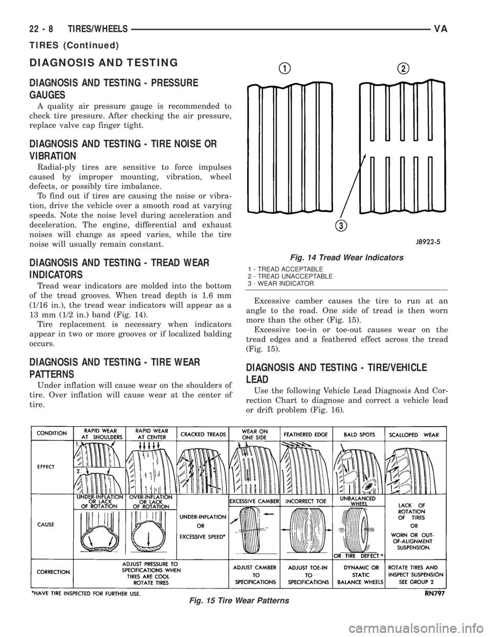
Tread wear indicators are molded into the bottom
of the tread grooves. When tread depth is 1.6 mm
(1/16 in.), the tread wear indicators will appear as a
13 mm (1/2 in.) band (Fig. 14).
Tire replacement is necessary when indicators
appear in two or more grooves or if localized balding
occurs.
DIAGNOSIS AND TESTING - TIRE WEAR
PATTERNS
Under inflation will cause wear on the shoulders of
tire. Over inflation will cause wear at the center of
tire.Excessive camber causes the tire to run at an
angle to the road. One side of tread is then worn
more than the other (Fig. 15).
Excessive toe-in or toe-out causes wear on the
tread edges and a feathered effect across the tread
(Fig. 15).
DIAGNOSIS AND TESTING - TIRE/VEHICLE
LEAD
Use the following Vehicle Lead Diagnosis And Cor-
rection Chart to diagnose and correct a vehicle lead
or drift problem (Fig. 16).
Fig. 14 Tread Wear Indicators
1 - TREAD ACCEPTABLE
2 - TREAD UNACCEPTABLE
3 - WEAR INDICATOR
Fig. 15 Tire Wear Patterns
22 - 8 TIRES/WHEELSVA
TIRES (Continued)
Page 1033 of 1232

Fig. 16 VEHICLE LEAD DIAGNOSIS AND CORRECTION CHART
VATIRES/WHEELS 22 - 9
TIRES (Continued)
Page 1034 of 1232
STANDARD PROCEDURE - REPAIRING LEAKS
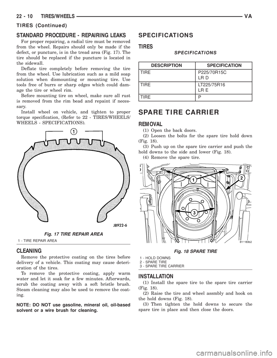
For proper repairing, a radial tire must be removed
from the wheel. Repairs should only be made if the
defect, or puncture, is in the tread area (Fig. 17). The
tire should be replaced if the puncture is located in
the sidewall.
Deflate tire completely before removing the tire
from the wheel. Use lubrication such as a mild soap
solution when dismounting or mounting tire. Use
tools free of burrs or sharp edges which could dam-
age the tire or wheel rim.
Before mounting tire on wheel, make sure all rust
is removed from the rim bead and repaint if neces-
sary.
Install wheel on vehicle, and tighten to proper
torque specification, (Refer to 22 - TIRES/WHEELS/
WHEELS - SPECIFICATIONS).
CLEANING
Remove the protective coating on the tires before
delivery of a vehicle. This coating may cause deteri-
oration of the tires.
To remove the protective coating, apply warm
water and let it soak for a few minutes. Afterwards,
scrub the coating away with a soft bristle brush.
Steam cleaning may also be used to remove the coat-
ing.
NOTE: DO NOT use gasoline, mineral oil, oil-based
solvent or a wire brush for cleaning.
SPECIFICATIONS
TIRES
SPECIFICATIONS
DESCRIPTION SPECIFICATION
TIRE P225/70R15C
LR D
TIRE LT225/75R16
LR E
TIRE P
SPARE TIRE CARRIER
REMOVAL
(1) Open the back doors.
(2) Loosen the bolts for the spare tire hold down
(Fig. 18).
(3) Push up on the spare tire carrier and push the
hold downs to the side and lower (Fig. 18).
(4) Remove the spare tire.
INSTALLATION
(1) Install the spare tire to the spare tire carrier
(Fig. 18).
(2) Raise the tire and wheel assmbly and hook on
the hold downs (Fig. 18).
(3) Then tighten the hold downs to secure the
spare tire in place and then close the doors.
Fig. 17 TIRE REPAIR AREA
1 - TIRE REPAIR AREA
Fig. 18 SPARE TIRE
1 - HOLD DOWNS
2 - SPARE TIRE
3 - SPARE TIRE CARRIER
22 - 10 TIRES/WHEELSVA
TIRES (Continued)
Page 1035 of 1232
WHEELS
DESCRIPTION
Original equipment wheels are designed for the
specified Maximum Vehicle Capacity.
All models use steel or aluminum wheels.
Aluminum wheels require special balance weights
and alignment equipment.
(1) On vehicles equipped with dual rear wheels,
The slots in the wheel must be aligned to provide
access to the valve stem.
OPERATION
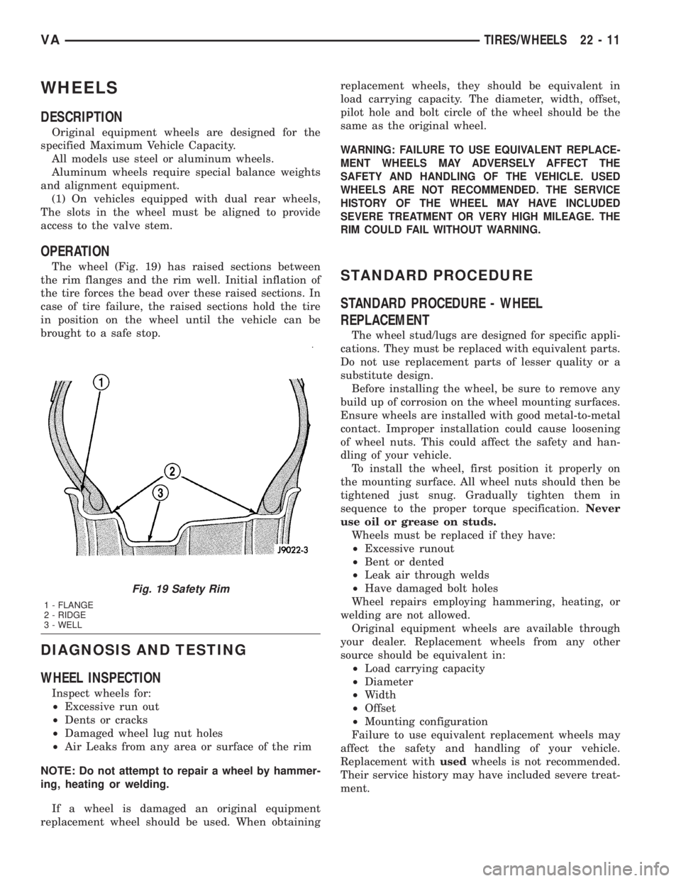
The wheel (Fig. 19) has raised sections between
the rim flanges and the rim well. Initial inflation of
the tire forces the bead over these raised sections. In
case of tire failure, the raised sections hold the tire
in position on the wheel until the vehicle can be
brought to a safe stop.
DIAGNOSIS AND TESTING
WHEEL INSPECTION
Inspect wheels for:
²Excessive run out
²Dents or cracks
²Damaged wheel lug nut holes
²Air Leaks from any area or surface of the rim
NOTE: Do not attempt to repair a wheel by hammer-
ing, heating or welding.
If a wheel is damaged an original equipment
replacement wheel should be used. When obtainingreplacement wheels, they should be equivalent in
load carrying capacity. The diameter, width, offset,
pilot hole and bolt circle of the wheel should be the
same as the original wheel.
WARNING: FAILURE TO USE EQUIVALENT REPLACE-
MENT WHEELS MAY ADVERSELY AFFECT THE
SAFETY AND HANDLING OF THE VEHICLE. USED
WHEELS ARE NOT RECOMMENDED. THE SERVICE
HISTORY OF THE WHEEL MAY HAVE INCLUDED
SEVERE TREATMENT OR VERY HIGH MILEAGE. THE
RIM COULD FAIL WITHOUT WARNING.
STANDARD PROCEDURE
STANDARD PROCEDURE - WHEEL
REPLACEMENT
The wheel stud/lugs are designed for specific appli-
cations. They must be replaced with equivalent parts.
Do not use replacement parts of lesser quality or a
substitute design.
Before installing the wheel, be sure to remove any
build up of corrosion on the wheel mounting surfaces.
Ensure wheels are installed with good metal-to-metal
contact. Improper installation could cause loosening
of wheel nuts. This could affect the safety and han-
dling of your vehicle.
To install the wheel, first position it properly on
the mounting surface. All wheel nuts should then be
tightened just snug. Gradually tighten them in
sequence to the proper torque specification.Never
use oil or grease on studs.
Wheels must be replaced if they have:
²Excessive runout
²Bent or dented
²Leak air through welds
²Have damaged bolt holes
Wheel repairs employing hammering, heating, or
welding are not allowed.
Original equipment wheels are available through
your dealer. Replacement wheels from any other
source should be equivalent in:
²Load carrying capacity
²Diameter
²Width
²Offset
²Mounting configuration
Failure to use equivalent replacement wheels may
affect the safety and handling of your vehicle.
Replacement withusedwheels is not recommended.
Their service history may have included severe treat-
ment.
Fig. 19 Safety Rim
1 - FLANGE
2 - RIDGE
3 - WELL
VATIRES/WHEELS 22 - 11
Page 1036 of 1232
STANDARD PROCEDURE - DUAL REAR WHEEL
INSTALLATION
The tires on both wheels must be completely raised
off the ground when tightening the lug nuts. This
will ensure correct wheel centering and maximum
wheel clamping.
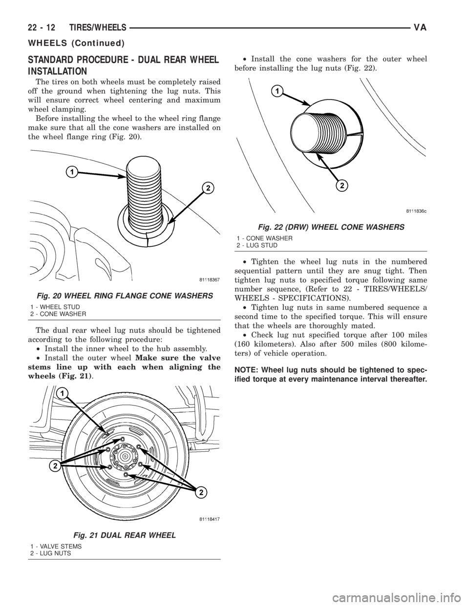
Before installing the wheel to the wheel ring flange
make sure that all the cone washers are installed on
the wheel flange ring (Fig. 20).
The dual rear wheel lug nuts should be tightened
according to the following procedure:
²Install the inner wheel to the hub assembly.
²Install the outer wheelMake sure the valve
stems line up with each when aligning the
wheels (Fig. 21).²Install the cone washers for the outer wheel
before installing the lug nuts (Fig. 22).
²Tighten the wheel lug nuts in the numbered
sequential pattern until they are snug tight. Then
tighten lug nuts to specified torque following same
number sequence, (Refer to 22 - TIRES/WHEELS/
WHEELS - SPECIFICATIONS).
²Tighten lug nuts in same numbered sequence a
second time to the specified torque. This will ensure
that the wheels are thoroughly mated.
²Check lug nut specified torque after 100 miles
(160 kilometers). Also after 500 miles (800 kilome-
ters) of vehicle operation.
NOTE: Wheel lug nuts should be tightened to spec-
ified torque at every maintenance interval thereafter.
Fig. 20 WHEEL RING FLANGE CONE WASHERS
1 - WHEEL STUD
2 - CONE WASHER
Fig. 21 DUAL REAR WHEEL
1 - VALVE STEMS
2 - LUG NUTS
Fig. 22 (DRW) WHEEL CONE WASHERS
1 - CONE WASHER
2 - LUG STUD
22 - 12 TIRES/WHEELSVA
WHEELS (Continued)
Page 1037 of 1232
REMOVAL
(1) Raise and support the vehicle.
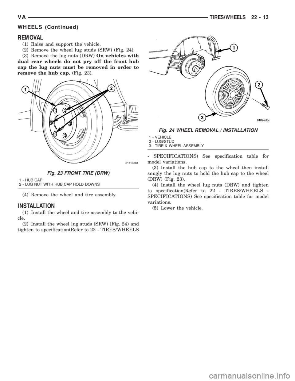
(2) Remove the wheel lug studs (SRW) (Fig. 24).
(3) Remove the lug nuts (DRW)On vehicles with
dual rear wheels do not pry off the front hub
cap the lug nuts must be removed in order to
remove the hub cap.(Fig. 23).
(4) Remove the wheel and tire assembly.
INSTALLATION
(1) Install the wheel and tire assembly to the vehi-
cle.
(2) Install the wheel lug studs (SRW) (Fig. 24) and
tighten to specification(Refer to 22 - TIRES/WHEELS- SPECIFICATIONS) See specification table for
model variations.
(3) Install the hub cap to the wheel then install
snugly the lug nuts to hold the hub cap to the wheel
(DRW) (Fig. 23).
(4) Install the wheel lug nuts (DRW) and tighten
to specification(Refer to 22 - TIRES/WHEELS -
SPECIFICATIONS) See specification table for model
variations.
(5) Lower the vehicle.
Fig. 23 FRONT TIRE (DRW)
1 - HUB CAP
2 - LUG NUT WITH HUB CAP HOLD DOWNS
Fig. 24 WHEEL REMOVAL / INSTALLATION
1 - VEHICLE
2 - LUG/STUD
3 - TIRE & WHEEL ASSEMBLY
VATIRES/WHEELS 22 - 13
WHEELS (Continued)