2005 MERCEDES-BENZ SPRINTER wheel
[x] Cancel search: wheelPage 1126 of 1232
BODY STRUCTURE
TABLE OF CONTENTS
page page
GAP AND FLUSH
SPECIFICATIONS.......................88OPENING DIMENSIONS
SPECIFICATIONS.......................90
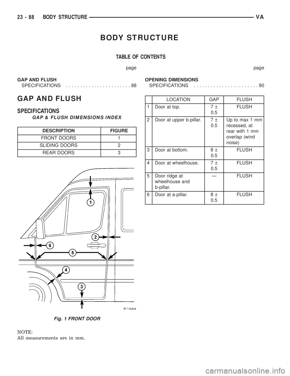
GAP AND FLUSH
SPECIFICATIONS
GAP & FLUSH DIMENSIONS INDEX
DESCRIPTION FIGURE
FRONT DOORS 1
SLIDING DOORS 2
REAR DOORS 3
NOTE:
All measurements are in mm.
LOCATION GAP FLUSH
1 Door at top. 7
0.5FLUSH
2 Door at upper b-pillar. 7
0.5Up to max 1 mm
recessed, at
rear with 1 mm
overlap (wind
noise)
3 Door at bottom. 8
0.5FLUSH
4 Door at wheelhouse. 7
0.5FLUSH
5 Door ridge at
wheelhouse and
b-pillar.Ð FLUSH
6 Door at a-pillar. 8
0.5FLUSH
Fig. 1 FRONT DOOR
23 - 88 BODY STRUCTUREVA
Page 1130 of 1232
²expansion valve
²air outlet temperature sensor
²mode doors
Vehicles equipped with the factory-installed
optional rear air conditioning system (Fig. 2) use a
common roof mounted assembly which includes:
²solenoid valve
²evaporator core
²evaporator temperature sensor
²expansion valve
²blower motor and wheel assembly
A heater booster is used to aid in warming the
engine coolant. The heater booster system can be
switched on while the vehicle is being driven to help
the engine reach its normal operating temperature
quickly and will help aid in heating up the air within
the passenger compartment quickly when requested
by the operator (Fig. 3).
OPERATION - HEATER AND AIR CONDITIONER
Outside air enters the vehicle through the hood
opening at the base of the windshield, and passesthrough the ventilation housing located in the engine
compartment into the heater housing located behind
the instrument panel. Air flow velocity is adjusted
with the blower motor speed selector thumbwheel on
the A/C-heater control. The air intake openings must
be kept free of snow, ice, leaves, and other obstruc-
tions for the HVAC system to receive a sufficient vol-
ume of outside air.
The automatic temperature control (ATC) system
controls interior temperature by taking actual values
from the temperature sensors and the CAN bus and
comparing them to the nominal value of the temper-
ature control switch. The electric pulsed heater valve
is then energized depending on the requested quan-
tity of heat and an electrically-operated water pump
gives a nearly constant water flow for exact temper-
ature regulation. If the solenoid is not energized, the
coolant circuit to the heat exchanger is fully open. To
control the temperature the solenoid valve is pulsed
by the ATC in periods of four seconds.
The mode control knob on the A/C-heater control is
used to direct the conditioned air flow to the selected
air outlets. The mode control knob operates the mode
doors by cables connected to the mode doors.
When the outside air contains smoke, oders, high
humidity, or if rapid cooling is desired, interior air
can by recirculated by selecting the Recirculation
Mode with the mode control knob. The mode control
knob operates the recirculation door through use of a
vaccum actuator. When the Recirculation Mode is
selected, the recirculation door is closed to prevent
outside air from entering the passenger compart-
ment.
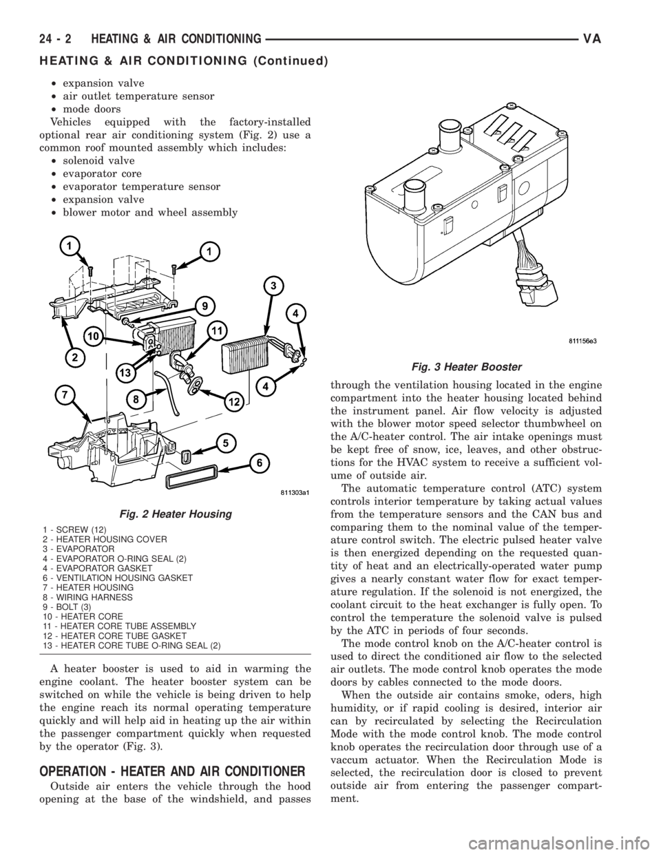
Fig. 2 Heater Housing
1 - SCREW (12)
2 - HEATER HOUSING COVER
3 - EVAPORATOR
4 - EVAPORATOR O-RING SEAL (2)
4 - EVAPORATOR GASKET
6 - VENTILATION HOUSING GASKET
7 - HEATER HOUSING
8 - WIRING HARNESS
9 - BOLT (3)
10 - HEATER CORE
11 - HEATER CORE TUBE ASSEMBLY
12 - HEATER CORE TUBE GASKET
13 - HEATER CORE TUBE O-RING SEAL (2)
Fig. 3 Heater Booster
24 - 2 HEATING & AIR CONDITIONINGVA
HEATING & AIR CONDITIONING (Continued)
Page 1136 of 1232
CONTROLS - FRONT
TABLE OF CONTENTS
page page
A/C COMPRESSOR CLUTCH
DESCRIPTION..........................8
OPERATION............................8
STANDARD PROCEDURE
STANDARD PROCEDURE - COMPRESSOR
CLUTCH AIR GAP......................9
STANDARD PROCEDURE - COMPRESSOR
CLUTCH BREAK-IN.....................9
REMOVAL.............................9
INSPECTION - COMPRESSOR CLUTCH/COIL . 10
INSTALLATION.........................11
A/C COMPRESSOR CLUTCH COIL
DIAGNOSIS AND TESTING - COMPRESSOR
CLUTCH COIL........................12
A/C HEATER CONTROL
DESCRIPTION.........................12
OPERATION...........................12
REMOVAL.............................12
INSTALLATION.........................13
A/C PRESSURE TRANSDUCER
DESCRIPTION.........................13
OPERATION...........................13
DIAGNOSIS AND TESTING - A/C PRESSURE
TRANSDUCER.......................13
REMOVAL.............................14
INSTALLATION.........................14
AIR OUTLET TEMPERATURE SENSOR
DESCRIPTION.........................14
OPERATION...........................15
REMOVAL.............................15
INSTALLATION.........................15
AMBIENT TEMPERATURE SENSOR
DESCRIPTION.........................15
OPERATION...........................15REMOVAL.............................15
INSTALLATION.........................16
BLOWER MOTOR RESISTOR BLOCK
DESCRIPTION.........................16
OPERATION...........................16
DIAGNOSIS AND TESTING - BLOWER
MOTOR RESISTOR BLOCK..............16
REMOVAL.............................16
INSTALLATION.........................17
BLOWER MOTOR SWITCH
DESCRIPTION.........................17
OPERATION...........................17
DIAGNOSIS AND TESTING - BLOWER
MOTOR SWITCH......................17
REMOVAL.............................17
EVAPORATOR TEMPERATURE SENSOR
DESCRIPTION.........................17
OPERATION...........................18
REMOVAL.............................18
INSTALLATION.........................18
IN-CAR TEMPERATURE SENSOR
DESCRIPTION.........................19
OPERATION...........................19
DIAGNOSIS AND TESTING................19
REMOVAL.............................19
MODE DOOR CABLES
REMOVAL.............................19
INSTALLATION.........................19
RECIRCULATION DOOR ACTUATOR
DESCRIPTION.........................20
OPERATION...........................20
REMOVAL.............................21
INSTALLATION.........................21
A/C COMPRESSOR CLUTCH
DESCRIPTION
The compressor clutch assembly consists of a sta-
tionary electromagnetic coil, a hub bearing and pul-
ley assembly, and a clutch plate (Fig. 1). The
electromagnetic coil unit and the hub bearing and
pulley assembly are each retained on the nose of the
compressor front housing with snap rings. The clutch
plate is keyed to the compressor shaft and secured
with a bolt.
The compressor clutch plate and pully, or the clutch
coil are available for seperate service replacement.
OPERATION
The compressor clutch components provide the
means to engage and disengage the compressor from
the engine serpentine accessory drive belt. When the
clutch coil is energized, it magnetically draws the
clutch into contact with the pulley and drives the
compressor shaft. When the coil is not energized, the
pulley freewheels on the clutch hub bearing, which is
part of the pulley.
24 - 8 CONTROLS - FRONTVA
Page 1140 of 1232
(11) Reconnect the engine wire harness connector
for the compressor clutch coil to the coil wire harness
connector on the top of the compressor.
(12) Reinstall the serpentine accessory drive belt
(Refer to 7 - COOLING/ACCESSORY DRIVE/DRIVE
BELTS - INSTALLATION).
(13) Reconnect the battery negative cable.
(14) If a new clutch plate and/or clutch pulley are
being installed, the new clutch components must be
burnished (Refer to 24 - HEATING & AIR CONDI-
TIONING/CONTROLS/A/C COMPRESSOR CLUTCH
- STANDARD PROCEDURE).
A/C COMPRESSOR CLUTCH
COIL
DIAGNOSIS AND TESTING - COMPRESSOR
CLUTCH COIL
The air conditioning compressor clutch coil electri-
cal circuit is controlled by the ATC control module
which is integral to the heater-A/C control. Begin
testing of a suspected compressor clutch coil problem
by performing the ATC Function Test using the
DRBIIItscan tool.
A/C HEATER CONTROL
DESCRIPTION
This ATC system uses a combination of electrical
and mechanical controls. These controls provide the
vehicle operator with a number of setting options to
help control the climate and comfort within the vehi-
cle.
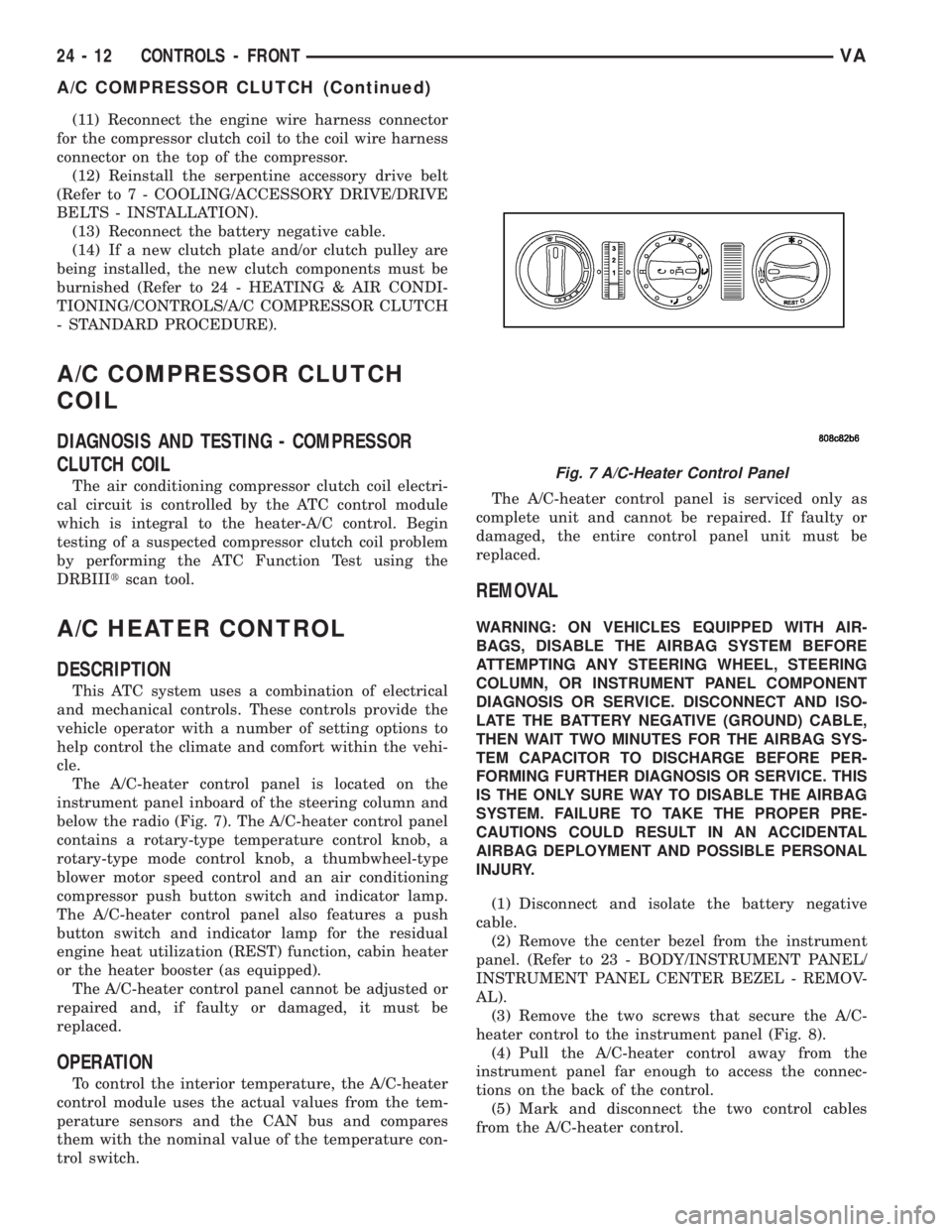
The A/C-heater control panel is located on the
instrument panel inboard of the steering column and
below the radio (Fig. 7). The A/C-heater control panel
contains a rotary-type temperature control knob, a
rotary-type mode control knob, a thumbwheel-type
blower motor speed control and an air conditioning
compressor push button switch and indicator lamp.
The A/C-heater control panel also features a push
button switch and indicator lamp for the residual
engine heat utilization (REST) function, cabin heater
or the heater booster (as equipped).
The A/C-heater control panel cannot be adjusted or
repaired and, if faulty or damaged, it must be
replaced.
OPERATION
To control the interior temperature, the A/C-heater
control module uses the actual values from the tem-
perature sensors and the CAN bus and compares
them with the nominal value of the temperature con-
trol switch.The A/C-heater control panel is serviced only as
complete unit and cannot be repaired. If faulty or
damaged, the entire control panel unit must be
replaced.
REMOVAL
WARNING: ON VEHICLES EQUIPPED WITH AIR-
BAGS, DISABLE THE AIRBAG SYSTEM BEFORE
ATTEMPTING ANY STEERING WHEEL, STEERING
COLUMN, OR INSTRUMENT PANEL COMPONENT
DIAGNOSIS OR SERVICE. DISCONNECT AND ISO-
LATE THE BATTERY NEGATIVE (GROUND) CABLE,
THEN WAIT TWO MINUTES FOR THE AIRBAG SYS-
TEM CAPACITOR TO DISCHARGE BEFORE PER-
FORMING FURTHER DIAGNOSIS OR SERVICE. THIS
IS THE ONLY SURE WAY TO DISABLE THE AIRBAG
SYSTEM. FAILURE TO TAKE THE PROPER PRE-
CAUTIONS COULD RESULT IN AN ACCIDENTAL
AIRBAG DEPLOYMENT AND POSSIBLE PERSONAL
INJURY.
(1) Disconnect and isolate the battery negative
cable.
(2) Remove the center bezel from the instrument
panel. (Refer to 23 - BODY/INSTRUMENT PANEL/
INSTRUMENT PANEL CENTER BEZEL - REMOV-
AL).
(3) Remove the two screws that secure the A/C-
heater control to the instrument panel (Fig. 8).
(4) Pull the A/C-heater control away from the
instrument panel far enough to access the connec-
tions on the back of the control.
(5) Mark and disconnect the two control cables
from the A/C-heater control.
Fig. 7 A/C-Heater Control Panel
24 - 12 CONTROLS - FRONTVA
A/C COMPRESSOR CLUTCH (Continued)
Page 1141 of 1232
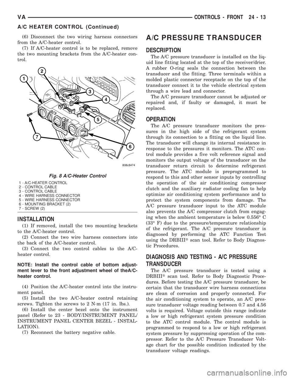
(6) Disconnect the two wiring harness connectors
from the A/C-heater control.
(7) If A/C-heater control is to be replaced, remove
the two mounting brackets from the A/C-heater con-
trol.
INSTALLATION
(1) If removed, install the two mounting brackets
to the A/C-heater control.
(2) Connect the two wire harness connectors into
the back of the A/C-heater control.
(3) Connect the two control cables to the A/C-
heater control.
NOTE: Install the control cable of bottom adjust-
ment lever to the front adjustment wheel of theA/C-
heater control.
(4) Position the A/C-heater control into the instru-
ment panel.
(5) Install the two A/C-heater control retaining
screws. Tighten the screws to 2 N´m (17 in. lbs.).
(6) Install the center bezel onto the instrument
panel (Refer to 23 - BODY/INSTRUMENT PANEL/
INSTRUMENT PANEL CENTER BEZEL - INSTAL-
LATION).
(7) Reconnect the battery negative cable.
A/C PRESSURE TRANSDUCER
DESCRIPTION
The A/C pressure transducer is installed on the liq-
uid line fitting located at the top of the receiver/drier.
A rubber O-ring seals the connection between the
transducer and the fitting. Three terminals within a
molded plastic connector receptacle on the top of the
transducer connect it to the vehicle electrical system
through a wire lead and connector.
The A/C pressure transducer cannot be adjusted or
repaired and, if faulty or damaged, it must be
replaced.
OPERATION
The A/C pressure transducer monitors the pres-
sures in the high side of the refrigerant system
through its connection to a fitting on the liquid line.
The transducer will change its internal resistance in
response to the pressures it monitors. The ATC con-
trol module provides a five volt reference signal and
monitors the output voltage of the transducer on the
transducer return circuit to determine refrigerant
pressure. The ATC module is preprogrammed to
respond to this and other sensor inputs by controlling
the operation of the air conditioning compressor
clutch and the auxiliary radiator cooling fan to help
optimize air conditioning system performance and to
protect the system components from damage. The
A/C pressure transducer input to the ATC module
also prevents the A/C compressor clutch from engag-
ing when the ambient temperature is below 0.556É C
(33É F) due to the pressure/temperature relationship
of the refrigerant. The A/C pressure transducer is
diagnosed by performing the ATC Function Test
using the DRBIIItscan tool. Refer to Body Diagnos-
tic Procedures.
DIAGNOSIS AND TESTING - A/C PRESSURE
TRANSDUCER
The A/C pressure transducer is tested using a
DRBIIItscan tool. Refer to Body Diagnostic Proce-
dures. Before testing the A/C pressure transducer, be
certain that the transducer wire harness connections
are clean of corrosion and properly connected. For
the air conditioning system to operate, an A/C pres-
sure transducer voltage reading between 0.7 and 4.56
volts is required. Voltage outside this range indicate
a low or high refrigerant system pressure condition
to the ATC control module. The control module is
programmed to respond to a low or high refrigerant
system pressure by suppressing operation of the com-
pressor. Refer to the A/C Pressure Transducer Volt-
age chart for the possible condition indicated by the
transducer voltage readings.
Fig. 8 A/C-Heater Control
1 - A/C-HEATER CONTROL
2 - CONTROL CABLE
3 - CONTROL CABLE
4 - WIRE HARNESS CONNECTOR
5 - WIRE HARNESS CONNECTOR
6 - MOUNTING BRACKET (2)
7 - SCREW (2)
VACONTROLS - FRONT 24 - 13
A/C HEATER CONTROL (Continued)
Page 1144 of 1232
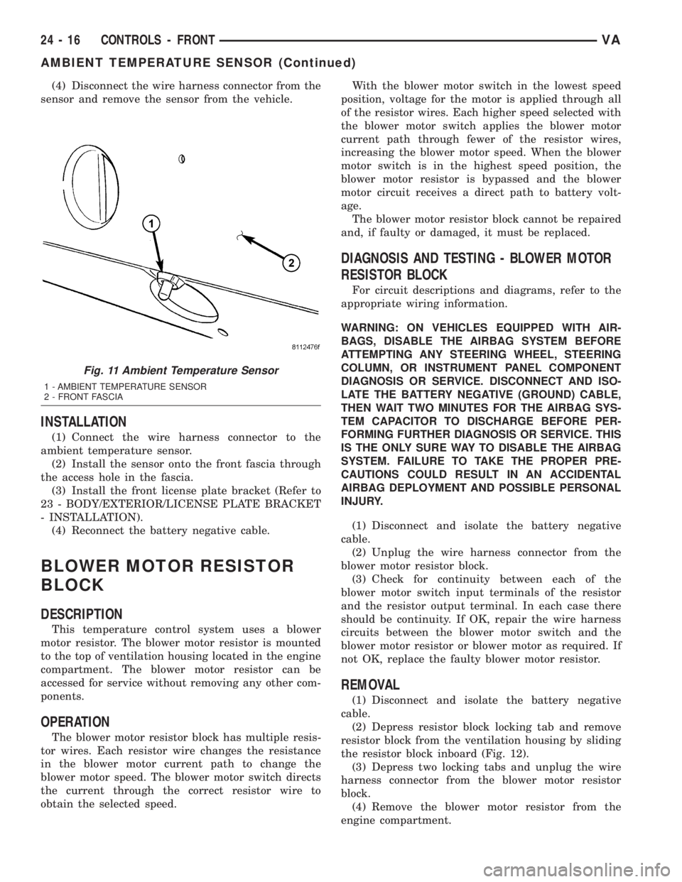
(4) Disconnect the wire harness connector from the
sensor and remove the sensor from the vehicle.
INSTALLATION
(1) Connect the wire harness connector to the
ambient temperature sensor.
(2) Install the sensor onto the front fascia through
the access hole in the fascia.
(3) Install the front license plate bracket (Refer to
23 - BODY/EXTERIOR/LICENSE PLATE BRACKET
- INSTALLATION).
(4) Reconnect the battery negative cable.
BLOWER MOTOR RESISTOR
BLOCK
DESCRIPTION
This temperature control system uses a blower
motor resistor. The blower motor resistor is mounted
to the top of ventilation housing located in the engine
compartment. The blower motor resistor can be
accessed for service without removing any other com-
ponents.
OPERATION
The blower motor resistor block has multiple resis-
tor wires. Each resistor wire changes the resistance
in the blower motor current path to change the
blower motor speed. The blower motor switch directs
the current through the correct resistor wire to
obtain the selected speed.With the blower motor switch in the lowest speed
position, voltage for the motor is applied through all
of the resistor wires. Each higher speed selected with
the blower motor switch applies the blower motor
current path through fewer of the resistor wires,
increasing the blower motor speed. When the blower
motor switch is in the highest speed position, the
blower motor resistor is bypassed and the blower
motor circuit receives a direct path to battery volt-
age.
The blower motor resistor block cannot be repaired
and, if faulty or damaged, it must be replaced.
DIAGNOSIS AND TESTING - BLOWER MOTOR
RESISTOR BLOCK
For circuit descriptions and diagrams, refer to the
appropriate wiring information.
WARNING: ON VEHICLES EQUIPPED WITH AIR-
BAGS, DISABLE THE AIRBAG SYSTEM BEFORE
ATTEMPTING ANY STEERING WHEEL, STEERING
COLUMN, OR INSTRUMENT PANEL COMPONENT
DIAGNOSIS OR SERVICE. DISCONNECT AND ISO-
LATE THE BATTERY NEGATIVE (GROUND) CABLE,
THEN WAIT TWO MINUTES FOR THE AIRBAG SYS-
TEM CAPACITOR TO DISCHARGE BEFORE PER-
FORMING FURTHER DIAGNOSIS OR SERVICE. THIS
IS THE ONLY SURE WAY TO DISABLE THE AIRBAG
SYSTEM. FAILURE TO TAKE THE PROPER PRE-
CAUTIONS COULD RESULT IN AN ACCIDENTAL
AIRBAG DEPLOYMENT AND POSSIBLE PERSONAL
INJURY.
(1) Disconnect and isolate the battery negative
cable.
(2) Unplug the wire harness connector from the
blower motor resistor block.
(3) Check for continuity between each of the
blower motor switch input terminals of the resistor
and the resistor output terminal. In each case there
should be continuity. If OK, repair the wire harness
circuits between the blower motor switch and the
blower motor resistor or blower motor as required. If
not OK, replace the faulty blower motor resistor.
REMOVAL
(1) Disconnect and isolate the battery negative
cable.
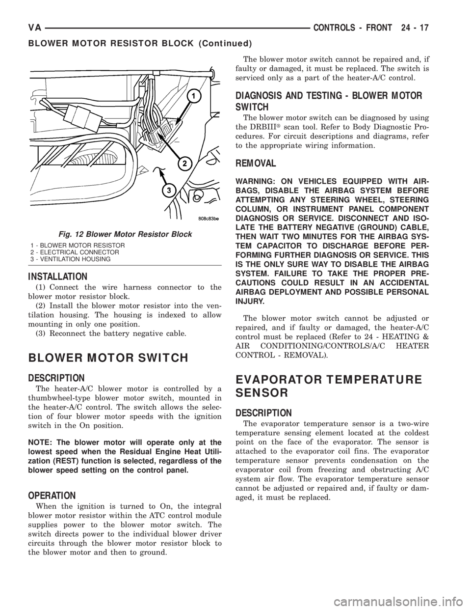
(2) Depress resistor block locking tab and remove
resistor block from the ventilation housing by sliding
the resistor block inboard (Fig. 12).
(3) Depress two locking tabs and unplug the wire
harness connector from the blower motor resistor
block.
(4) Remove the blower motor resistor from the
engine compartment.
Fig. 11 Ambient Temperature Sensor
1 - AMBIENT TEMPERATURE SENSOR
2 - FRONT FASCIA
24 - 16 CONTROLS - FRONTVA
AMBIENT TEMPERATURE SENSOR (Continued)
Page 1145 of 1232
INSTALLATION
(1) Connect the wire harness connector to the
blower motor resistor block.
(2) Install the blower motor resistor into the ven-
tilation housing. The housing is indexed to allow
mounting in only one position.
(3) Reconnect the battery negative cable.
BLOWER MOTOR SWITCH
DESCRIPTION
The heater-A/C blower motor is controlled by a
thumbwheel-type blower motor switch, mounted in
the heater-A/C control. The switch allows the selec-
tion of four blower motor speeds with the ignition
switch in the On position.
NOTE: The blower motor will operate only at the
lowest speed when the Residual Engine Heat Utili-
zation (REST) function is selected, regardless of the
blower speed setting on the control panel.
OPERATION
When the ignition is turned to On, the integral
blower motor resistor within the ATC control module
supplies power to the blower motor switch. The
switch directs power to the individual blower driver
circuits through the blower motor resistor block to
the blower motor and then to ground.The blower motor switch cannot be repaired and, if
faulty or damaged, it must be replaced. The switch is
serviced only as a part of the heater-A/C control.
DIAGNOSIS AND TESTING - BLOWER MOTOR
SWITCH
The blower motor switch can be diagnosed by using
the DRBIIItscan tool. Refer to Body Diagnostic Pro-
cedures. For circuit descriptions and diagrams, refer
to the appropriate wiring information.
REMOVAL
WARNING: ON VEHICLES EQUIPPED WITH AIR-
BAGS, DISABLE THE AIRBAG SYSTEM BEFORE
ATTEMPTING ANY STEERING WHEEL, STEERING
COLUMN, OR INSTRUMENT PANEL COMPONENT
DIAGNOSIS OR SERVICE. DISCONNECT AND ISO-
LATE THE BATTERY NEGATIVE (GROUND) CABLE,
THEN WAIT TWO MINUTES FOR THE AIRBAG SYS-
TEM CAPACITOR TO DISCHARGE BEFORE PER-
FORMING FURTHER DIAGNOSIS OR SERVICE. THIS
IS THE ONLY SURE WAY TO DISABLE THE AIRBAG
SYSTEM. FAILURE TO TAKE THE PROPER PRE-
CAUTIONS COULD RESULT IN AN ACCIDENTAL
AIRBAG DEPLOYMENT AND POSSIBLE PERSONAL
INJURY.
The blower motor switch cannot be adjusted or
repaired, and if faulty or damaged, the heater-A/C
control must be replaced (Refer to 24 - HEATING &
AIR CONDITIONING/CONTROLS/A/C HEATER
CONTROL - REMOVAL).
EVAPORATOR TEMPERATURE
SENSOR
DESCRIPTION
The evaporator temperature sensor is a two-wire
temperature sensing element located at the coldest
point on the face of the evaporator. The sensor is
attached to the evaporator coil fins. The evaporator
temperature sensor prevents condensation on the
evaporator coil from freezing and obstructing A/C
system air flow. The evaporator temperature sensor
cannot be adjusted or repaired and, if faulty or dam-
aged, it must be replaced.
Fig. 12 Blower Motor Resistor Block
1 - BLOWER MOTOR RESISTOR
2 - ELECTRICAL CONNECTOR
3 - VENTILATION HOUSING
VACONTROLS - FRONT 24 - 17
BLOWER MOTOR RESISTOR BLOCK (Continued)
Page 1147 of 1232
(12) Install the cover to the instrument cluster.
(13) Install glove compartment.
(14) Install the radio (Refer to 8 - ELECTRICAL/
AUDIO/RADIO - INSTALLATION).
(15) Reconnect the battery negative cable.
IN-CAR TEMPERATURE
SENSOR
DESCRIPTION
The in-car temperature sensor measures the actual
air temperature within the passenger compartment.
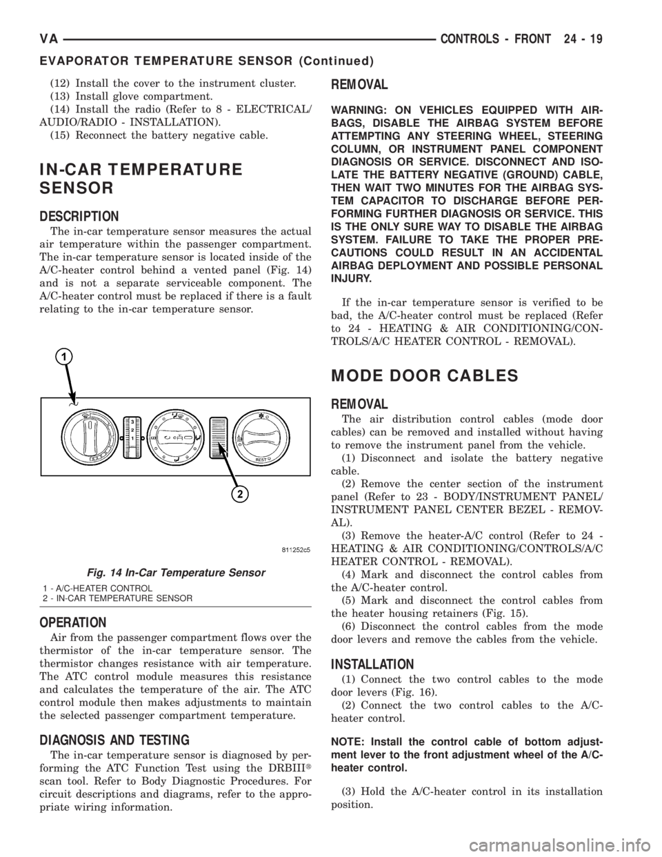
The in-car temperature sensor is located inside of the
A/C-heater control behind a vented panel (Fig. 14)
and is not a separate serviceable component. The
A/C-heater control must be replaced if there is a fault
relating to the in-car temperature sensor.
OPERATION
Air from the passenger compartment flows over the
thermistor of the in-car temperature sensor. The
thermistor changes resistance with air temperature.
The ATC control module measures this resistance
and calculates the temperature of the air. The ATC
control module then makes adjustments to maintain
the selected passenger compartment temperature.
DIAGNOSIS AND TESTING
The in-car temperature sensor is diagnosed by per-
forming the ATC Function Test using the DRBIIIt
scan tool. Refer to Body Diagnostic Procedures. For
circuit descriptions and diagrams, refer to the appro-
priate wiring information.
REMOVAL
WARNING: ON VEHICLES EQUIPPED WITH AIR-
BAGS, DISABLE THE AIRBAG SYSTEM BEFORE
ATTEMPTING ANY STEERING WHEEL, STEERING
COLUMN, OR INSTRUMENT PANEL COMPONENT
DIAGNOSIS OR SERVICE. DISCONNECT AND ISO-
LATE THE BATTERY NEGATIVE (GROUND) CABLE,
THEN WAIT TWO MINUTES FOR THE AIRBAG SYS-
TEM CAPACITOR TO DISCHARGE BEFORE PER-
FORMING FURTHER DIAGNOSIS OR SERVICE. THIS
IS THE ONLY SURE WAY TO DISABLE THE AIRBAG
SYSTEM. FAILURE TO TAKE THE PROPER PRE-
CAUTIONS COULD RESULT IN AN ACCIDENTAL
AIRBAG DEPLOYMENT AND POSSIBLE PERSONAL
INJURY.
If the in-car temperature sensor is verified to be
bad, the A/C-heater control must be replaced (Refer
to 24 - HEATING & AIR CONDITIONING/CON-
TROLS/A/C HEATER CONTROL - REMOVAL).
MODE DOOR CABLES
REMOVAL
The air distribution control cables (mode door
cables) can be removed and installed without having
to remove the instrument panel from the vehicle.
(1) Disconnect and isolate the battery negative
cable.
(2) Remove the center section of the instrument
panel (Refer to 23 - BODY/INSTRUMENT PANEL/
INSTRUMENT PANEL CENTER BEZEL - REMOV-
AL).
(3) Remove the heater-A/C control (Refer to 24 -
HEATING & AIR CONDITIONING/CONTROLS/A/C
HEATER CONTROL - REMOVAL).
(4) Mark and disconnect the control cables from
the A/C-heater control.
(5) Mark and disconnect the control cables from
the heater housing retainers (Fig. 15).
(6) Disconnect the control cables from the mode
door levers and remove the cables from the vehicle.
INSTALLATION
(1) Connect the two control cables to the mode
door levers (Fig. 16).
(2) Connect the two control cables to the A/C-
heater control.
NOTE: Install the control cable of bottom adjust-
ment lever to the front adjustment wheel of the A/C-
heater control.
(3) Hold the A/C-heater control in its installation
position.
Fig. 14 In-Car Temperature Sensor
1 - A/C-HEATER CONTROL
2 - IN-CAR TEMPERATURE SENSOR
VACONTROLS - FRONT 24 - 19
EVAPORATOR TEMPERATURE SENSOR (Continued)