2005 MERCEDES-BENZ SPRINTER wheel
[x] Cancel search: wheelPage 1151 of 1232
DIAGNOSIS AND TESTING
Before testing the rear blower motor switch, verify
that the front A/C system is functional by performing
the ATC Fuction Test using the DRBIIItscan tool.
Use a volt/ohmmeter to test the rear blower motor
switch. For circuit descriptions and diagrams, refer
to the appropriate wiring information. The wiring
information includes wiring diagrams, proper wire
and connector repair procedures, details of wire har-
ness routing and retention, connector pin-out infor-
mation and location views for the various wire
harness connectors, splices and grounds.
WARNING: ON VEHICLES EQUIPPED WITH AIR-
BAGS, DISABLE THE AIRBAG SYSTEM BEFORE
ATTEMPTING ANY STEERING WHEEL, STEERING
COLUMN, OR INSTRUMENT PANEL COMPONENT
DIAGNOSIS OR SERVICE. DISCONNECT AND ISO-
LATE THE BATTERY NEGATIVE (GROUND) CABLE,
THEN WAIT TWO MINUTES FOR THE AIRBAG SYS-
TEM CAPACITOR TO DISCHARGE BEFORE PER-
FORMING FURTHER DIAGNOSIS OR SERVICE. THIS
IS THE ONLY SURE WAY TO DISABLE THE AIRBAG
SYSTEM. FAILURE TO TAKE THE PROPER PRE-
CAUTIONS COULD RESULT IN ACCIDENTAL AIR-
BAG DEPLOYMENT AND POSSIBLE PERSONAL
INJURY.
(1) Disconnect and isolate the battery negative
cable.
(2) Unplug the wire harness connector from the
rear blower motor switch.
(3) Check for continuity between terminal 10 and
terminals 1, 7 and 4 of the blower motor switch. In
all instances, there should be continuity.
NOTE: To check the switch's internal circuits, con-
nect the negative lead of the ohmmeter to terminal
10 and the positive ohmmeter lead to terminals 1, 7
and 4. To check the switch's integral light emitting
diodes, reverse the ohmmeter leads.
(4) Check for continuity between the rear blower
motor switch terminals 3 and 7 as you move the
blower motor switch to each of the two speed posi-
tions, and the Off position. There should be continu-
ity in only one blower motor switch speed position.
(5) Check for continuity between the rear blower
motor switch terminals 4 and 8 as you move the
blower motor switch to each of the two speed posi-
tions, and the Off position. There should be continu-
ity in only the other blower motor switch speed
position.
(6) If OK, test and repair the rear blower motor
switch wire harness circuits. If not OK, replace the
faulty rear blower motor switch.
REMOVAL
NOTE: The rear blower motor switch is used only
on models with the optional rear A/C unit.
(1) Disconnect and isolate the battery negative
cable.
(2) Remove the blower motor switch from the
switch panel.
(3) Disconnect the wire harness connector from the
rear blower motor switch and remove the switch from
the vehicle.
INSTALLATION
(1) Connect the wire harness connector to the rear
blower motor switch.
(2) Install the blower motor switch into the switch
panel.
(3) Reconnect the battery negative cable.
BLOWER MOTOR RELAY
DESCRIPTION
The blower motor relays are an International Stan-
dards Organization (ISO)-type relay. The relays are
electro-mechanical devices which when energized,
directs fused battery current to the rear blower
motor. The relay coils are energized when they
receives a voltage signal from the blower motor
switch.
OPERATION
When the rear blower motor switch is in the low
speed position, the switch directs a voltage signal to
the high side of rear blower relay #1 and energizes
its relay coil. When energized, the low side of blower
relay #1 directs fused battery current through an
integral blower resistor to the rear blower motor.
When in the high speed position, the rear blower
switch directs a voltage signal to the high side of
rear blower relay #2 and energizes its relay coil.
When energized, the low side of blower relay #2
directs fused battery current through an integral
blower resistor to the rear blower motor.
The rear blower motor relays are located in the
relay block of the rear evaporator housing. Refer to
the appropriate wiring diagrams for more informa-
tion.
The blower motor relay cannot be repaired and, if
faulty or damaged, it must be replaced.
VACONTROLS - REAR 24 - 23
BLOWER MOTOR SWITCH (Continued)
Page 1157 of 1232
TEMPERATURE CONTROL
DESCRIPTION
The optional rear heater-A/C unit output tempera-
ture is controlled by a thumbwheel-type control,
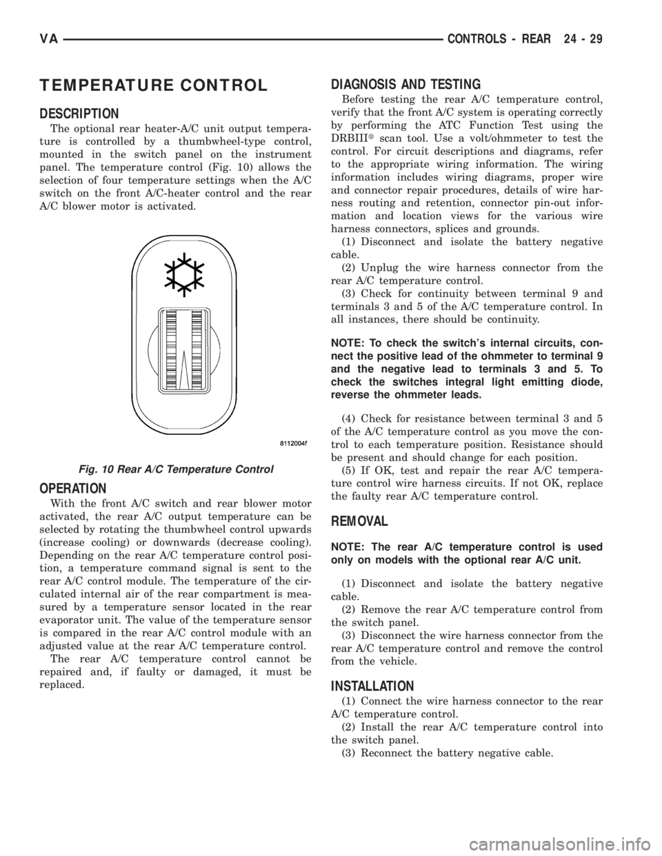
mounted in the switch panel on the instrument
panel. The temperature control (Fig. 10) allows the
selection of four temperature settings when the A/C
switch on the front A/C-heater control and the rear
A/C blower motor is activated.
OPERATION
With the front A/C switch and rear blower motor
activated, the rear A/C output temperature can be
selected by rotating the thumbwheel control upwards
(increase cooling) or downwards (decrease cooling).
Depending on the rear A/C temperature control posi-
tion, a temperature command signal is sent to the
rear A/C control module. The temperature of the cir-
culated internal air of the rear compartment is mea-
sured by a temperature sensor located in the rear
evaporator unit. The value of the temperature sensor
is compared in the rear A/C control module with an
adjusted value at the rear A/C temperature control.
The rear A/C temperature control cannot be
repaired and, if faulty or damaged, it must be
replaced.
DIAGNOSIS AND TESTING
Before testing the rear A/C temperature control,
verify that the front A/C system is operating correctly
by performing the ATC Function Test using the
DRBIIItscan tool. Use a volt/ohmmeter to test the
control. For circuit descriptions and diagrams, refer
to the appropriate wiring information. The wiring
information includes wiring diagrams, proper wire
and connector repair procedures, details of wire har-
ness routing and retention, connector pin-out infor-
mation and location views for the various wire
harness connectors, splices and grounds.
(1) Disconnect and isolate the battery negative
cable.
(2) Unplug the wire harness connector from the
rear A/C temperature control.
(3) Check for continuity between terminal 9 and
terminals 3 and 5 of the A/C temperature control. In
all instances, there should be continuity.
NOTE: To check the switch's internal circuits, con-
nect the positive lead of the ohmmeter to terminal 9
and the negative lead to terminals 3 and 5. To
check the switches integral light emitting diode,
reverse the ohmmeter leads.
(4) Check for resistance between terminal 3 and 5
of the A/C temperature control as you move the con-
trol to each temperature position. Resistance should
be present and should change for each position.
(5) If OK, test and repair the rear A/C tempera-
ture control wire harness circuits. If not OK, replace
the faulty rear A/C temperature control.
REMOVAL
NOTE: The rear A/C temperature control is used
only on models with the optional rear A/C unit.
(1) Disconnect and isolate the battery negative
cable.
(2) Remove the rear A/C temperature control from
the switch panel.
(3) Disconnect the wire harness connector from the
rear A/C temperature control and remove the control
from the vehicle.
INSTALLATION
(1) Connect the wire harness connector to the rear
A/C temperature control.
(2) Install the rear A/C temperature control into
the switch panel.
(3) Reconnect the battery negative cable.
Fig. 10 Rear A/C Temperature Control
VACONTROLS - REAR 24 - 29
Page 1159 of 1232
DISTRIBUTION - FRONT
TABLE OF CONTENTS
page page
AIR FILTER
REMOVAL.............................31
INSTALLATION.........................31
AIR OUTLETS
REMOVAL.............................31
INSTALLATION.........................32
BLOWER MOTOR
REMOVAL.............................32
INSTALLATION.........................33
DEFROSTER DUCTS
REMOVAL.............................33
INSTALLATION.........................33FLOOR DISTRIBUTION DUCTS
REMOVAL.............................33
INSTALLATION.........................34
HVAC HOUSING
REMOVAL.............................34
DISASSEMBLY.........................36
ASSEMBLY............................36
INSTALLATION.........................36
INSTRUMENT PANEL DUCTS
REMOVAL.............................37
INSTALLATION.........................38
AIR FILTER
REMOVAL
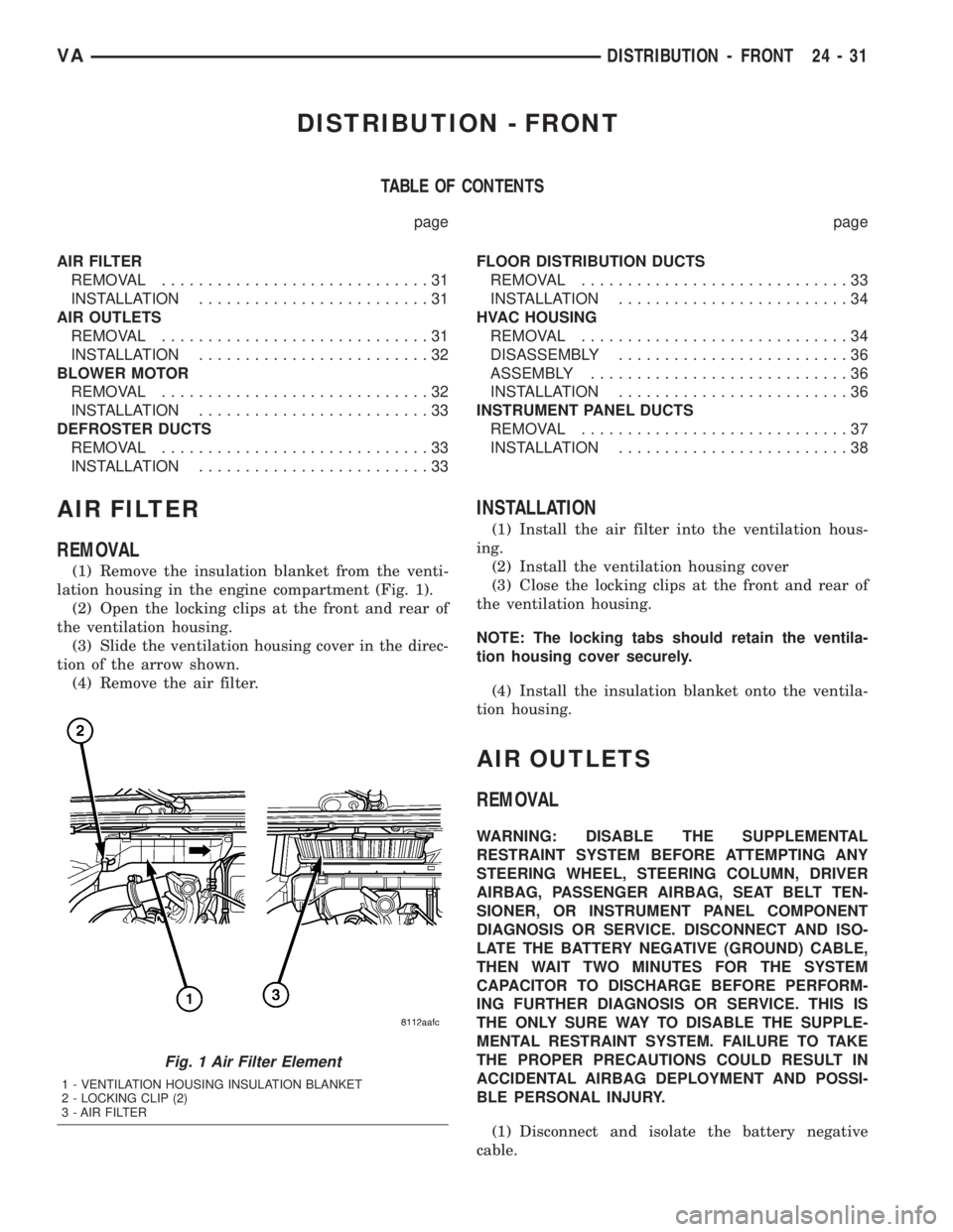
(1) Remove the insulation blanket from the venti-
lation housing in the engine compartment (Fig. 1).
(2) Open the locking clips at the front and rear of
the ventilation housing.
(3) Slide the ventilation housing cover in the direc-
tion of the arrow shown.
(4) Remove the air filter.
INSTALLATION
(1) Install the air filter into the ventilation hous-
ing.
(2) Install the ventilation housing cover
(3) Close the locking clips at the front and rear of
the ventilation housing.
NOTE: The locking tabs should retain the ventila-
tion housing cover securely.
(4) Install the insulation blanket onto the ventila-
tion housing.
AIR OUTLETS
REMOVAL
WARNING: DISABLE THE SUPPLEMENTAL
RESTRAINT SYSTEM BEFORE ATTEMPTING ANY
STEERING WHEEL, STEERING COLUMN, DRIVER
AIRBAG, PASSENGER AIRBAG, SEAT BELT TEN-
SIONER, OR INSTRUMENT PANEL COMPONENT
DIAGNOSIS OR SERVICE. DISCONNECT AND ISO-
LATE THE BATTERY NEGATIVE (GROUND) CABLE,
THEN WAIT TWO MINUTES FOR THE SYSTEM
CAPACITOR TO DISCHARGE BEFORE PERFORM-
ING FURTHER DIAGNOSIS OR SERVICE. THIS IS
THE ONLY SURE WAY TO DISABLE THE SUPPLE-
MENTAL RESTRAINT SYSTEM. FAILURE TO TAKE
THE PROPER PRECAUTIONS COULD RESULT IN
ACCIDENTAL AIRBAG DEPLOYMENT AND POSSI-
BLE PERSONAL INJURY.
(1) Disconnect and isolate the battery negative
cable.
Fig. 1 Air Filter Element
1 - VENTILATION HOUSING INSULATION BLANKET
2 - LOCKING CLIP (2)
3 - AIR FILTER
VADISTRIBUTION - FRONT 24 - 31
Page 1162 of 1232
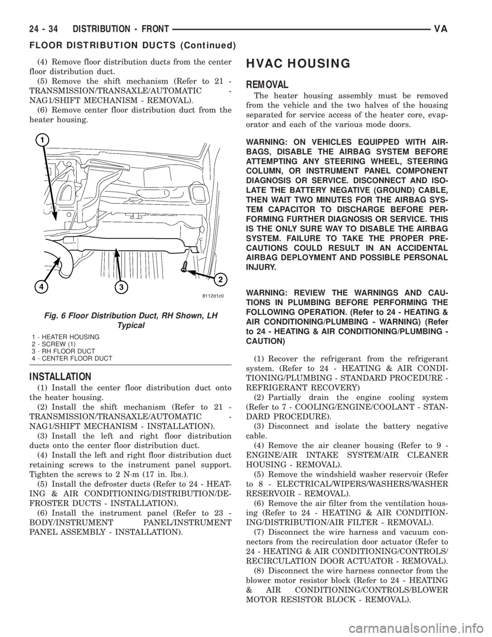
(4) Remove floor distribution ducts from the center
floor distribution duct.
(5) Remove the shift mechanism (Refer to 21 -
TRANSMISSION/TRANSAXLE/AUTOMATIC -
NAG1/SHIFT MECHANISM - REMOVAL).
(6) Remove center floor distribution duct from the
heater housing.
INSTALLATION
(1) Install the center floor distribution duct onto
the heater housing.
(2) Install the shift mechanism (Refer to 21 -
TRANSMISSION/TRANSAXLE/AUTOMATIC -
NAG1/SHIFT MECHANISM - INSTALLATION).
(3) Install the left and right floor distribution
ducts onto the center floor distribution duct.
(4) Install the left and right floor distribution duct
retaining screws to the instrument panel support.
Tighten the screws to 2 N´m (17 in. lbs.).
(5) Install the defroster ducts (Refer to 24 - HEAT-
ING & AIR CONDITIONING/DISTRIBUTION/DE-
FROSTER DUCTS - INSTALLATION).
(6) Install the instrument panel (Refer to 23 -
BODY/INSTRUMENT PANEL/INSTRUMENT
PANEL ASSEMBLY - INSTALLATION).
HVAC HOUSING
REMOVAL
The heater housing assembly must be removed
from the vehicle and the two halves of the housing
separated for service access of the heater core, evap-
orator and each of the various mode doors.
WARNING: ON VEHICLES EQUIPPED WITH AIR-
BAGS, DISABLE THE AIRBAG SYSTEM BEFORE
ATTEMPTING ANY STEERING WHEEL, STEERING
COLUMN, OR INSTRUMENT PANEL COMPONENT
DIAGNOSIS OR SERVICE. DISCONNECT AND ISO-
LATE THE BATTERY NEGATIVE (GROUND) CABLE,
THEN WAIT TWO MINUTES FOR THE AIRBAG SYS-
TEM CAPACITOR TO DISCHARGE BEFORE PER-
FORMING FURTHER DIAGNOSIS OR SERVICE. THIS
IS THE ONLY SURE WAY TO DISABLE THE AIRBAG
SYSTEM. FAILURE TO TAKE THE PROPER PRE-
CAUTIONS COULD RESULT IN AN ACCIDENTAL
AIRBAG DEPLOYMENT AND POSSIBLE PERSONAL
INJURY.
WARNING: REVIEW THE WARNINGS AND CAU-
TIONS IN PLUMBING BEFORE PERFORMING THE
FOLLOWING OPERATION. (Refer to 24 - HEATING &
AIR CONDITIONING/PLUMBING - WARNING) (Refer
to 24 - HEATING & AIR CONDITIONING/PLUMBING -
CAUTION)
(1) Recover the refrigerant from the refrigerant
system. (Refer to 24 - HEATING & AIR CONDI-
TIONING/PLUMBING - STANDARD PROCEDURE -
REFRIGERANT RECOVERY)
(2) Partially drain the engine cooling system
(Refer to 7 - COOLING/ENGINE/COOLANT - STAN-
DARD PROCEDURE).
(3) Disconnect and isolate the battery negative
cable.
(4) Remove the air cleaner housing (Refer to 9 -
ENGINE/AIR INTAKE SYSTEM/AIR CLEANER
HOUSING - REMOVAL).
(5) Remove the windshield washer reservoir (Refer
to 8 - ELECTRICAL/WIPERS/WASHERS/WASHER
RESERVOIR - REMOVAL).
(6) Remove the air filter from the ventilation hous-
ing (Refer to 24 - HEATING & AIR CONDITION-
ING/DISTRIBUTION/AIR FILTER - REMOVAL).
(7) Disconnect the wire harness and vacuum con-
nectors from the recirculation door actuator (Refer to
24 - HEATING & AIR CONDITIONING/CONTROLS/
RECIRCULATION DOOR ACTUATOR - REMOVAL).
(8) Disconnect the wire harness connector from the
blower motor resistor block (Refer to 24 - HEATING
& AIR CONDITIONING/CONTROLS/BLOWER
MOTOR RESISTOR BLOCK - REMOVAL).
Fig. 6 Floor Distribution Duct, RH Shown, LH
Typical
1 - HEATER HOUSING
2 - SCREW (1)
3 - RH FLOOR DUCT
4 - CENTER FLOOR DUCT
24 - 34 DISTRIBUTION - FRONTVA
FLOOR DISTRIBUTION DUCTS (Continued)
Page 1175 of 1232
When servicing the air conditioning system, a
R-134a refrigerant recovery/recycling/charging sta-
tion that meets SAE Standard J2210 must be used.
Contact an automotive service equipment supplier for
refrigerant recovery/recycling/charging equipment.
Refer to the operating instructions supplied by the
equipment manufacturer for proper care and use of
this equipment.
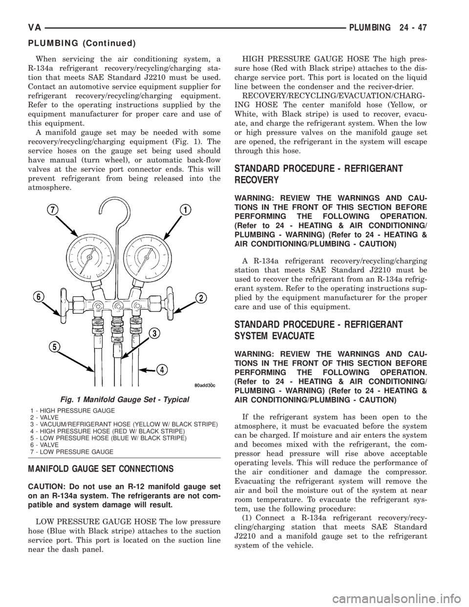
A manifold gauge set may be needed with some
recovery/recycling/charging equipment (Fig. 1). The
service hoses on the gauge set being used should
have manual (turn wheel), or automatic back-flow
valves at the service port connector ends. This will
prevent refrigerant from being released into the
atmosphere.
MANIFOLD GAUGE SET CONNECTIONS
CAUTION: Do not use an R-12 manifold gauge set
on an R-134a system. The refrigerants are not com-
patible and system damage will result.
LOW PRESSURE GAUGE HOSE The low pressure
hose (Blue with Black stripe) attaches to the suction
service port. This port is located on the suction line
near the dash panel.HIGH PRESSURE GAUGE HOSE The high pres-
sure hose (Red with Black stripe) attaches to the dis-
charge service port. This port is located on the liquid
line between the condenser and the reciver-drier.
RECOVERY/RECYCLING/EVACUATION/CHARG-
ING HOSE The center manifold hose (Yellow, or
White, with Black stripe) is used to recover, evacu-
ate, and charge the refrigerant system. When the low
or high pressure valves on the manifold gauge set
are opened, the refrigerant in the system will escape
through this hose.
STANDARD PROCEDURE - REFRIGERANT
RECOVERY
WARNING: REVIEW THE WARNINGS AND CAU-
TIONS IN THE FRONT OF THIS SECTION BEFORE
PERFORMING THE FOLLOWING OPERATION.
(Refer to 24 - HEATING & AIR CONDITIONING/
PLUMBING - WARNING) (Refer to 24 - HEATING &
AIR CONDITIONING/PLUMBING - CAUTION)
A R-134a refrigerant recovery/recycling/charging
station that meets SAE Standard J2210 must be
used to recover the refrigerant from an R-134a refrig-
erant system. Refer to the operating instructions sup-
plied by the equipment manufacturer for the proper
care and use of this equipment.
STANDARD PROCEDURE - REFRIGERANT
SYSTEM EVACUATE
WARNING: REVIEW THE WARNINGS AND CAU-
TIONS IN THE FRONT OF THIS SECTION BEFORE
PERFORMING THE FOLLOWING OPERATION.
(Refer to 24 - HEATING & AIR CONDITIONING/
PLUMBING - WARNING) (Refer to 24 - HEATING &
AIR CONDITIONING/PLUMBING - CAUTION)
If the refrigerant system has been open to the
atmosphere, it must be evacuated before the system
can be charged. If moisture and air enters the system
and becomes mixed with the refrigerant, the com-
pressor head pressure will rise above acceptable
operating levels. This will reduce the performance of
the air conditioner and damage the compressor.
Evacuating the refrigerant system will remove the
air and boil the moisture out of the system at near
room temperature. To evacuate the refrigerant sys-
tem, use the following procedure:
(1) Connect a R-134a refrigerant recovery/recy-
cling/charging station that meets SAE Standard
J2210 and a manifold gauge set to the refrigerant
system of the vehicle.
Fig. 1 Manifold Gauge Set - Typical
1 - HIGH PRESSURE GAUGE
2 - VALVE
3 - VACUUM/REFRIGERANT HOSE (YELLOW W/ BLACK STRIPE)
4 - HIGH PRESSURE HOSE (RED W/ BLACK STRIPE)
5 - LOW PRESSURE HOSE (BLUE W/ BLACK STRIPE)
6 - VALVE
7 - LOW PRESSURE GAUGE
VAPLUMBING 24 - 47
PLUMBING (Continued)
Page 1183 of 1232
REMOVAL
WARNING: ON VEHICLES EQUIPPED WITH AIR-
BAGS, DISABLE THE AIRBAG SYSTEM BEFORE
ATTEMPTING ANY STEERING WHEEL, STEERING
COLUMN, OR INSTRUMENT PANEL COMPONENT
DIAGNOSIS OR SERVICE. DISCONNECT AND ISO-
LATE THE BATTERY NEGATIVE (GROUND) CABLE,
THEN WAIT TWO MINUTES FOR THE AIRBAG SYS-
TEM CAPACITOR TO DISCHARGE BEFORE PER-
FORMING FURTHER DIAGNOSIS OR SERVICE. THIS
IS THE ONLY SURE WAY TO DISABLE THE AIRBAG
SYSTEM. FAILURE TO TAKE THE PROPER PRE-
CAUTIONS COULD RESULT IN AN ACCIDENTAL
AIRBAG DEPLOYMENT AND POSSIBLE PERSONAL
INJURY.
WARNING: REVIEW THE WARNINGS AND CAU-
TIONS IN THE FRONT OF THIS SECTION BEFORE
PERFORMING THE FOLLOWING OPERATION (Refer
to 24 - HEATING & AIR CONDITIONING/PLUMBING -
WARNING) and (Refer to 24 - HEATING & AIR CON-
DITIONING/PLUMBING - CAUTION).
(1) Remove the heater housing (Refer to 24 -
HEATING & AIR CONDITIONING/DISTRIBUTION/
HVAC HOUSING - REMOVAL).
(2) Disassemble the heater housing to access the
evaporator (Refer to 24 - HEATING & AIR CONDI-
TIONING/DISTRIBUTION/HVAC HOUSING - DIS-
ASSEMBLY).
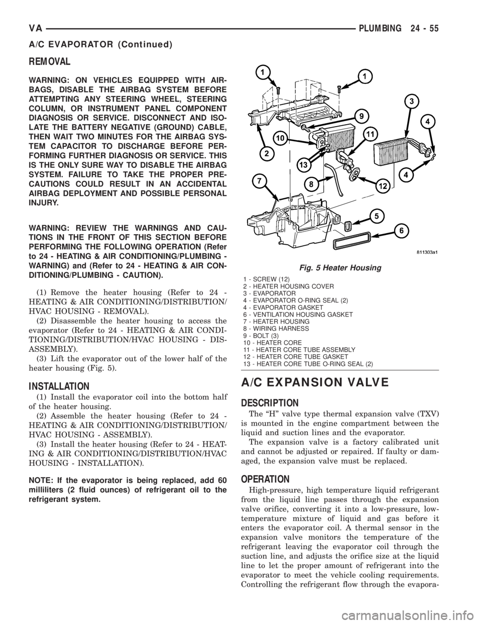
(3) Lift the evaporator out of the lower half of the
heater housing (Fig. 5).
INSTALLATION
(1) Install the evaporator coil into the bottom half
of the heater housing.
(2) Assemble the heater housing (Refer to 24 -
HEATING & AIR CONDITIONING/DISTRIBUTION/
HVAC HOUSING - ASSEMBLY).
(3) Install the heater housing (Refer to 24 - HEAT-
ING & AIR CONDITIONING/DISTRIBUTION/HVAC
HOUSING - INSTALLATION).
NOTE: If the evaporator is being replaced, add 60
milliliters (2 fluid ounces) of refrigerant oil to the
refrigerant system.
A/C EXPANSION VALVE
DESCRIPTION
The ªHº valve type thermal expansion valve (TXV)
is mounted in the engine compartment between the
liquid and suction lines and the evaporator.
The expansion valve is a factory calibrated unit
and cannot be adjusted or repaired. If faulty or dam-
aged, the expansion valve must be replaced.
OPERATION
High-pressure, high temperature liquid refrigerant
from the liquid line passes through the expansion
valve orifice, converting it into a low-pressure, low-
temperature mixture of liquid and gas before it
enters the evaporator coil. A thermal sensor in the
expansion valve monitors the temperature of the
refrigerant leaving the evaporator coil through the
suction line, and adjusts the orifice size at the liquid
line to let the proper amount of refrigerant into the
evaporator to meet the vehicle cooling requirements.
Controlling the refrigerant flow through the evapora-
Fig. 5 Heater Housing
1 - SCREW (12)
2 - HEATER HOUSING COVER
3 - EVAPORATOR
4 - EVAPORATOR O-RING SEAL (2)
4 - EVAPORATOR GASKET
6 - VENTILATION HOUSING GASKET
7 - HEATER HOUSING
8 - WIRING HARNESS
9 - BOLT (3)
10 - HEATER CORE
11 - HEATER CORE TUBE ASSEMBLY
12 - HEATER CORE TUBE GASKET
13 - HEATER CORE TUBE O-RING SEAL (2)
VAPLUMBING 24 - 55
A/C EVAPORATOR (Continued)
Page 1186 of 1232
blower motor speed controls the volume of air flowing
through the heater housing.
The heater core cannot be repaired and, if faulty or
damaged, it must be replaced.
REMOVAL
WARNING: ON VEHICLES EQUIPPED WITH AIR-
BAGS, DISABLE THE AIRBAG SYSTEM BEFORE
ATTEMPTING ANY STEERING WHEEL, STEERING
COLUMN, OR INSTRUMENT PANEL COMPONENT
DIAGNOSIS OR SERVICE. DISCONNECT AND ISO-
LATE THE BATTERY NEGATIVE (GROUND) CABLE,
THEN WAIT TWO MINUTES FOR THE AIRBAG SYS-
TEM CAPACITOR TO DISCHARGE BEFORE PER-
FORMING FURTHER DIAGNOSIS OR SERVICE. THIS
IS THE ONLY SURE WAY TO DISABLE THE AIRBAG
SYSTEM. FAILURE TO TAKE THE PROPER PRE-
CAUTIONS COULD RESULT IN AN ACCIDENTAL
AIRBAG DEPLOYMENT AND POSSIBLE PERSONAL
INJURY.
WARNING: REVIEW THE WARNINGS AND CAU-
TIONS IN THE FRONT OF THIS SECTION BEFORE
PERFORMING THE FOLLOWING OPERATION (Refer
to 24 - HEATING & AIR CONDITIONING/PLUMBING -
WARNING) and (Refer to 24 - HEATING & AIR CON-
DITIONING/PLUMBING - CAUTION).
(1) Remove the heater housing (Refer to 24 -
HEATING & AIR CONDITIONING/DISTRIBUTION/
HVAC HOUSING - REMOVAL).
(2) Disassemble the heater housing to access the
heater core (Refer to 24 - HEATING & AIR CONDI-
TIONING/DISTRIBUTION/HVAC HOUSING - DIS-
ASSEMBLY).
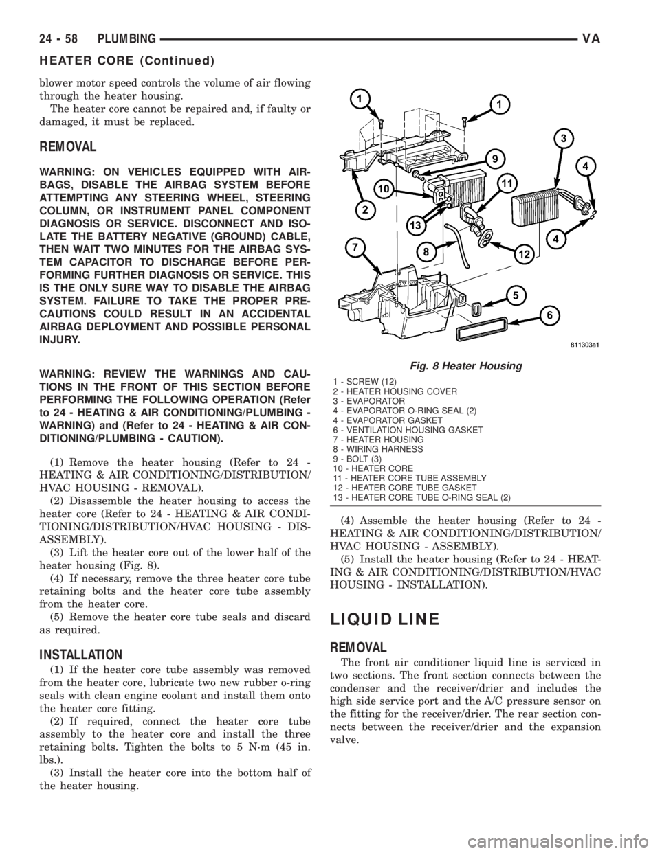
(3) Lift the heater core out of the lower half of the
heater housing (Fig. 8).
(4) If necessary, remove the three heater core tube
retaining bolts and the heater core tube assembly
from the heater core.
(5) Remove the heater core tube seals and discard
as required.
INSTALLATION
(1) If the heater core tube assembly was removed
from the heater core, lubricate two new rubber o-ring
seals with clean engine coolant and install them onto
the heater core fitting.
(2) If required, connect the heater core tube
assembly to the heater core and install the three
retaining bolts. Tighten the bolts to 5 N´m (45 in.
lbs.).
(3) Install the heater core into the bottom half of
the heater housing.(4) Assemble the heater housing (Refer to 24 -
HEATING & AIR CONDITIONING/DISTRIBUTION/
HVAC HOUSING - ASSEMBLY).
(5) Install the heater housing (Refer to 24 - HEAT-
ING & AIR CONDITIONING/DISTRIBUTION/HVAC
HOUSING - INSTALLATION).
LIQUID LINE
REMOVAL
The front air conditioner liquid line is serviced in
two sections. The front section connects between the
condenser and the receiver/drier and includes the
high side service port and the A/C pressure sensor on
the fitting for the receiver/drier. The rear section con-
nects between the receiver/drier and the expansion
valve.
Fig. 8 Heater Housing
1 - SCREW (12)
2 - HEATER HOUSING COVER
3 - EVAPORATOR
4 - EVAPORATOR O-RING SEAL (2)
4 - EVAPORATOR GASKET
6 - VENTILATION HOUSING GASKET
7 - HEATER HOUSING
8 - WIRING HARNESS
9 - BOLT (3)
10 - HEATER CORE
11 - HEATER CORE TUBE ASSEMBLY
12 - HEATER CORE TUBE GASKET
13 - HEATER CORE TUBE O-RING SEAL (2)
24 - 58 PLUMBINGVA
HEATER CORE (Continued)
Page 1211 of 1232
INDEX
ABS INDICATOR - DESCRIPTION..........8J-9
ABS INDICATOR - OPERATION...........8J-9
A/C COMPRESSOR - DESCRIPTION......24-49
A/C COMPRESSOR - INSTALLATION......24-51
A/C COMPRESSOR - OPERATION........24-49
A/C COMPRESSOR - REMOVAL.........24-50
A/C COMPRESSOR CLUTCH -
DESCRIPTION........................24-8
A/C COMPRESSOR CLUTCH -
OPERATION..........................24-8
A/C CONDENSER - DESCRIPTION........24-52
A/C CONDENSER - INSTALLATION.......24-52
A/C CONDENSER - OPERATION..........24-52
A/C CONDENSER - REMOVAL...........24-52
A/C DISCHARGE LINE - INSTALLATION . . . 24-54
A/C DISCHARGE LINE - REMOVAL.......24-53
A/C EVAPORATOR - DESCRIPTION.......24-54
A/C EVAPORATOR - INSTALLATION......24-55
A/C EVAPORATOR - OPERATION.........24-54
A/C EVAPORATOR - REMOVAL..........24-55
A/C EXPANSION VALVE - DESCRIPTION . . . 24-55
A/C EXPANSION VALVE - DIAGNOSIS
AND TESTING.......................24-56
A/C EXPANSION VALVE - INSTALLATION . . 24-56
A/C EXPANSION VALVE - OPERATION.....24-55
A/C EXPANSION VALVE - REMOVAL.......24-56
A/C HEATER CONTROL - DESCRIPTION . . . 24-12
A/C HEATER CONTROL - INSTALLATION . . . 24-13
A/C HEATER CONTROL - OPERATION.....24-12
A/C HEATER CONTROL - REMOVAL......24-12
A/C HOUSING - INSTALLATION, REAR....24-41
A/C HOUSING - REMOVAL, REAR........24-40
A/C PERFORMANCE TEST - DIAGNOSIS
AND TESTING........................24-3
A/C PRESSURE TRANSDUCER -
DESCRIPTION.......................24-13
A/C PRESSURE TRANSDUCER -
DIAGNOSIS AND TESTING.............24-13
A/C PRESSURE TRANSDUCER -
INSTALLATION.......................24-14
A/C PRESSURE TRANSDUCER -
OPERATION.........................24-13
A/C PRESSURE TRANSDUCER -
REMOVAL..........................24-14
A/C SYSTEM, SPECIFICATIONS...........24-5
ACCELERATOR PEDAL POSITION
SENSOR - DESCRIPTION...............14-17
ACCESSORY DRIVE BELT - DIAGNOSIS
AND TESTING.........................7-5
ACCESSORY SWITCH BEZEL -
INSTALLATION.......................23-54
ACCESSORY SWITCH BEZEL - REMOVAL . . 23-54
ACTUATOR - DESCRIPTION,
RECIRCULATION DOOR................24-20
ACTUATOR - INSTALLATION, INSIDE
HANDLE.......................23-34,23-37
ACTUATOR - INSTALLATION,
RECIRCULATION DOOR................24-21
ACTUATOR - OPERATION,
RECIRCULATION DOOR................24-20
ACTUATOR - REMOVAL, INSIDE HANDLE . 23-34,
23-37
ACTUATOR - REMOVAL, RECIRCULATION
DOOR.............................24-21
ADAPTATION - STANDARD PROCEDURE,
TCM................................8E-8
ADDING ADDITIONAL COOLANT -
STANDARD PROCEDURE................7-11
ADDITIONAL COOLANT - STANDARD
PROCEDURE, ADDING..................7-11
ADJUSTER - INSTALLATION, SEAT BELT
TURNING LOOP.....................8O-34
ADJUSTER - REMOVAL, SEAT BELT
TURNING LOOP.....................8O-33
ADJUSTERS - FRONT - INSTALLATION,
SEAT ..............................23-78
ADJUSTERS - FRONT - REMOVAL, SEAT . . 23-78
AFTER A SUPPLEMENTAL RESTRAINT
DEPLOYMENT - STANDARD
PROCEDURE, SERVICE.................8O-6
AIR CLEANER ELEMENT - INSTALLATION . . 9-20
AIR CLEANER ELEMENT - REMOVAL
......9-20
AIR CLEANER HOUSING - INSTALLATION
. . 9-20
AIR CLEANER HOUSING - REMOVAL
......9-20
AIR CONDITIONER - DESCRIPTION,
HEATER
.............................24-1
AIR CONDITIONER - OPERATION,
HEATER
.............................24-2AIR COOLER AND PLUMBING -
CLEANING, CHARGE...................11-5
AIR COOLER AND PLUMBING -
DESCRIPTION, CHARGE................11-4
AIR COOLER AND PLUMBING -
INSPECTION, CHARGE.................11-5
AIR COOLER AND PLUMBING -
INSTALLATION, CHARGE................11-5
AIR COOLER AND PLUMBING -
OPERATION, CHARGE..................11-4
AIR COOLER AND PLUMBING -
REMOVAL, CHARGE...................11-5
AIR COOLER SYSTEM - LEAKS -
DIAGNOSIS AND TESTING, CHARGE.......11-4
AIR FILTER - INSTALLATION.......24-31,24-39
AIR FILTER - REMOVAL..........24-31,24-39
AIR FLOW (MAF) SENSOR -
DESCRIPTION, MANIFOLD.............14-30
AIR FLOW (MAF) SENSOR -
INSTALLATION, MANIFOLD.............14-31
AIR FLOW (MAF) SENSOR - OPERATION,
MANIFOLD..........................14-30
AIR FLOW (MAF) SENSOR - REMOVAL,
MANIFOLD..........................14-31
AIR GAP - STANDARD PROCEDURE,
COMPRESSOR CLUTCH................24-9
AIR IN FUEL SYSTEM - DIAGNOSIS AND
TESTING............................14-2
AIR OUTLET TEMPERATURE SENSOR -
DESCRIPTION.......................24-14
AIR OUTLET TEMPERATURE SENSOR -
INSTALLATION.......................24-15
AIR OUTLET TEMPERATURE SENSOR -
OPERATION.........................24-15
AIR OUTLET TEMPERATURE SENSOR -
REMOVAL..........................24-15
AIR OUTLETS - INSTALLATION..........24-32
AIR OUTLETS - REMOVAL.............24-31
AIR TEMPERATURE SENSOR -
DESCRIPTION, INLET.................14-29
AIR TEMPERATURE SENSOR -
INSTALLATION, INLET.................14-30
AIR TEMPERATURE SENSOR -
OPERATION, INLET...................14-29
AIR TEMPERATURE SENSOR -
REMOVAL, INLET....................14-30
AIRBAG - DESCRIPTION, DRIVER........8O-16
AIRBAG - DESCRIPTION, PASSENGER....8O-23
AIRBAG - INSTALLATION, DRIVER.......8O-18
AIRBAG - INSTALLATION, PASSENGER . . . 8O-26
AIRBAG - OPERATION, DRIVER.........8O-17
AIRBAG - OPERATION, PASSENGER......8O-24
AIRBAG - REMOVAL, DRIVER...........8O-17
AIRBAG - REMOVAL, PASSENGER.......8O-24
AIRBAG BRACKET - INSTALLATION,
PASSENGER........................8O-27
AIRBAG BRACKET - REMOVAL,
PASSENGER........................8O-27
AIRBAG CONTROL MODULE -
DESCRIPTION........................8O-8
AIRBAG CONTROL MODULE -
INSTALLATION......................8O-11
AIRBAG CONTROL MODULE -
OPERATION..........................8O-9
AIRBAG CONTROL MODULE - REMOVAL . . 8O-10
AIRBAG INDICATOR - DESCRIPTION......8J-10
AIRBAG INDICATOR - OPERATION.......8J-10
ALB CONTROLLER - INSTALLATION
.......5-15
ALB CONTROLLER - REMOVAL
...........5-15
ALB LEVER - INSTALLATION
.............5-15
ALB LEVER - REMOVAL
................5-15
ALIGNMENT - DESCRIPTION, WHEEL
......2-17
ALIGNMENT - SPECIFICATIONS, WHEEL
....2-19
ALUMINUM THREAD REPAIR -
STANDARD PROCEDURE
...............21-27
AMBIENT TEMPERATURE INDICATOR -
DESCRIPTION
.......................8J-11
AMBIENT TEMPERATURE INDICATOR -
OPERATION
.........................8J-11
AMBIENT TEMPERATURE SENSOR -
DESCRIPTION
.......................24-15
AMBIENT TEMPERATURE SENSOR -
INSTALLATION
.......................24-16
AMBIENT TEMPERATURE SENSOR -
OPERATION
.........................24-15
AMBIENT TEMPERATURE SENSOR -
REMOVAL
..........................24-15ANTENNA BODY & CABLE -
INSTALLATION.......................8A-1
ANTENNA BODY & CABLE - REMOVAL.....8A-1
ANTENNA CABLE - INSTALLATION,
INSTRUMENT PANEL..................8A-2
ANTENNA CABLE - REMOVAL,
INSTRUMENT PANEL..................8A-1
ANTILOCK BRAKE - DESCRIPTION,
CONTROLLER........................8E-3
ANTILOCK BRAKE - INSTALLATION,
CONTROLLER........................8E-3
ANTILOCK BRAKE - REMOVAL,
CONTROLLER........................8E-3
A-PILLAR TRIM - INSTALLATION........23-68
A-PILLAR TRIM - REMOVAL............23-67
ARM - DESCRIPTION, WIPER...........8R-13
ARM - INSTALLATION, CENTER ROLLER . . 23-38
ARM - INSTALLATION, LOWER CONTROL . . . 2-6
ARM - INSTALLATION, LOWER ROLLER . . . 23-38
ARM - INSTALLATION, UPPER ROLLER . . . 23-37
ARM - INSTALLATION, WIPER..........8R-14
ARM - OPERATION, WIPER............8R-14
ARM - REMOVAL, CENTER ROLLER......23-37
ARM - REMOVAL, LOWER CONTROL.......2-6
ARM - REMOVAL, LOWER ROLLER......23-38
ARM - REMOVAL, UPPER ROLLER.......23-37
ARM - REMOVAL, WIPER..............8R-14
ARMREST - INSTALLATION.............23-76
ARMREST - REMOVAL................23-76
ASH RECEIVER - INSTALLATION.........23-55
ASH RECEIVER - REMOVAL............23-55
ASH RECEIVER/CIGAR LIGHTER LAMP
UNIT - INSTALLATION.................8L-27
ASH RECEIVER/CIGAR LIGHTER LAMP
UNIT - REMOVAL....................8L-27
ASSIST HANDLE - INSTALLATION........23-68
ASSIST HANDLE - REMOVAL...........23-68
AUDIO, SPECIAL TOOLS................8A-1
AUTOMATIC TRANSMISSION -
DIAGNOSIS AND TESTING........21-23,21-24
AUTOMATIC TRANSMISSION - NAG1 -
DESCRIPTION........................21-2
AUTOMATIC TRANSMISSION - NAG1 -
OPERATION..........................21-4
AUTOMATIC TRANSMISSION - SPECIAL
TOOLS, NAG1.......................21-69
AUTOMATIC TRANSMISSION -
SPECIFICATIONS, NAG1...............21-68
AUTOMATIC TRANSMISSION FLUID -
NAG1 - DESCRIPTION...................0-4
AUTOMATIC TRANSMISSION FLUID -
OPERATION...........................0-4
AUXILIARY BATTERY INSTALLATION,
INSTALLATION.......................8F-13
AUXILIARY BATTERY REMOVAL,
REMOVAL..........................8F-13
AXLE - DESCRIPTION...................0-3
AXLE - DESCRIPTION, REAR.............3-10
AXLE - DIAGNOSIS AND TESTING, REAR . . . 3-10
AXLE - INSTALLATION, REAR............3-12
AXLE - OPERATION, REAR..............3-10
AXLE - REMOVAL, REAR................3-11
AXLE - SPECIAL TOOLS, REAR...........3-14
AXLE - SPECIFICATIONS, REAR..........3-13
AXLE BEARINGS/SEALS - INSTALLATION . . . 3-17
AXLE BEARINGS/SEALS - REMOVAL......3-17
AXLE HUB BEARINGS/SEALS -
INSTALLATION........................3-20
AXLE HUB BEARINGS/SEALS - REMOVAL . . 3-20
AXLE SHAFTS - DUAL REAR WHEELS -
INSTALLATION........................3-19
AXLE SHAFTS - DUAL REAR WHEELS -
REMOVAL...........................3-19
AXLE SHAFTS - INSTALLATION...........3-15
AXLE SHAFTS - REMOVAL..............3-15
B1 - ASSEMBLY, HOLDING CLUTCH.....21-113
B1 - DISASSEMBLY, HOLDING CLUTCH . . 21-112
B2 - ASSEMBLY, HOLDING CLUTCH.....21-116
B2 - DISASSEMBLY, HOLDING CLUTCH . . 21-115
BACK - FRONT - INSTALLATION, SEAT....23-77
BACK - FRONT - REMOVAL, SEAT
.......23-77
BACK CUSHION/COVER - REAR -
INSTALLATION, SEAT
.................23-80
BACK CUSHION/COVER - REAR -
REMOVAL, SEAT
.....................23-80
BACK SHIELD - INSTALLATION, REAR
SEAT
..............................23-79
BACK SHIELD - REMOVAL, REAR SEAT
. . . 23-79
VAINDEX 1
Description Group-Page Description Group-Page Description Group-Page