2005 MERCEDES-BENZ SPRINTER wheel
[x] Cancel search: wheelPage 885 of 1232
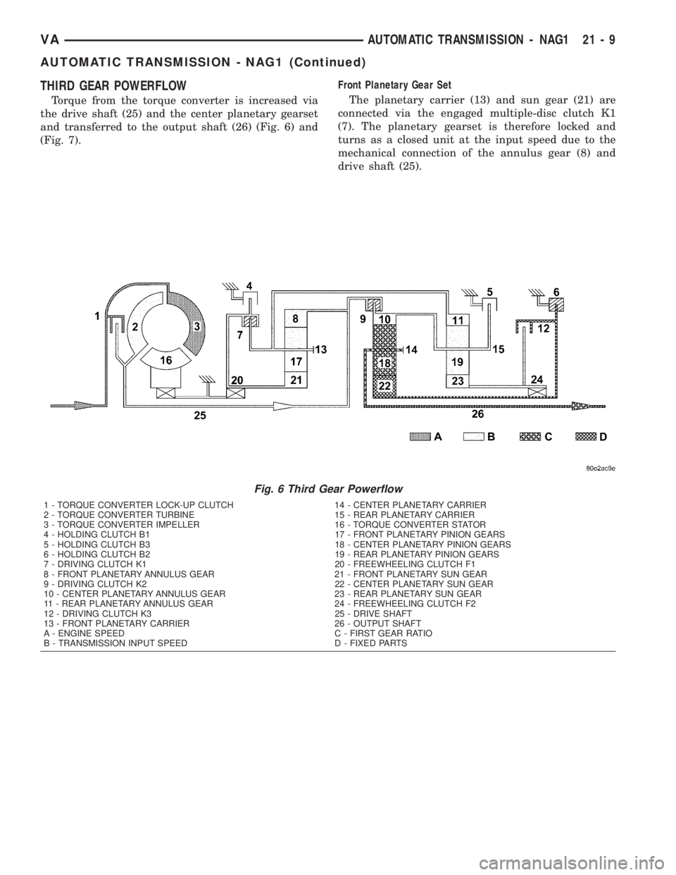
THIRD GEAR POWERFLOW
Torque from the torque converter is increased via
the drive shaft (25) and the center planetary gearset
and transferred to the output shaft (26) (Fig. 6) and
(Fig. 7).Front Planetary Gear Set
The planetary carrier (13) and sun gear (21) are
connected via the engaged multiple-disc clutch K1
(7). The planetary gearset is therefore locked and
turns as a closed unit at the input speed due to the
mechanical connection of the annulus gear (8) and
drive shaft (25).
Fig. 6 Third Gear Powerflow
1 - TORQUE CONVERTER LOCK-UP CLUTCH 14 - CENTER PLANETARY CARRIER
2 - TORQUE CONVERTER TURBINE 15 - REAR PLANETARY CARRIER
3 - TORQUE CONVERTER IMPELLER 16 - TORQUE CONVERTER STATOR
4 - HOLDING CLUTCH B1 17 - FRONT PLANETARY PINION GEARS
5 - HOLDING CLUTCH B3 18 - CENTER PLANETARY PINION GEARS
6 - HOLDING CLUTCH B2 19 - REAR PLANETARY PINION GEARS
7 - DRIVING CLUTCH K1 20 - FREEWHEELING CLUTCH F1
8 - FRONT PLANETARY ANNULUS GEAR 21 - FRONT PLANETARY SUN GEAR
9 - DRIVING CLUTCH K2 22 - CENTER PLANETARY SUN GEAR
10 - CENTER PLANETARY ANNULUS GEAR 23 - REAR PLANETARY SUN GEAR
11 - REAR PLANETARY ANNULUS GEAR 24 - FREEWHEELING CLUTCH F2
12 - DRIVING CLUTCH K3 25 - DRIVE SHAFT
13 - FRONT PLANETARY CARRIER 26 - OUTPUT SHAFT
A - ENGINE SPEED C - FIRST GEAR RATIO
B - TRANSMISSION INPUT SPEED D - FIXED PARTS
VAAUTOMATIC TRANSMISSION - NAG1 21 - 9
AUTOMATIC TRANSMISSION - NAG1 (Continued)
Page 886 of 1232
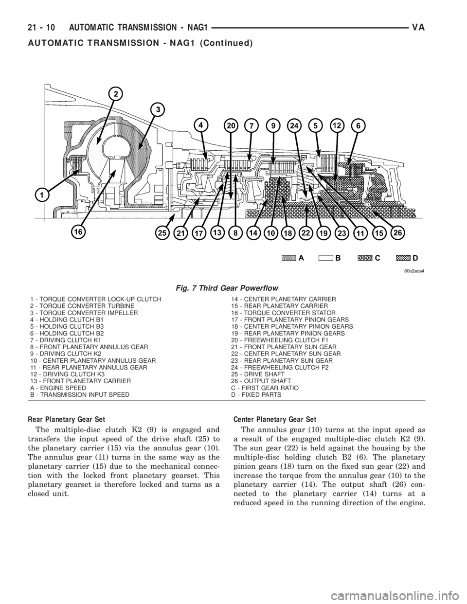
Rear Planetary Gear Set
The multiple-disc clutch K2 (9) is engaged and
transfers the input speed of the drive shaft (25) to
the planetary carrier (15) via the annulus gear (10).
The annulus gear (11) turns in the same way as the
planetary carrier (15) due to the mechanical connec-
tion with the locked front planetary gearset. This
planetary gearset is therefore locked and turns as a
closed unit.Center Planetary Gear Set
The annulus gear (10) turns at the input speed as
a result of the engaged multiple-disc clutch K2 (9).
The sun gear (22) is held against the housing by the
multiple-disc holding clutch B2 (6). The planetary
pinion gears (18) turn on the fixed sun gear (22) and
increase the torque from the annulus gear (10) to the
planetary carrier (14). The output shaft (26) con-
nected to the planetary carrier (14) turns at a
reduced speed in the running direction of the engine.
Fig. 7 Third Gear Powerflow
1 - TORQUE CONVERTER LOCK-UP CLUTCH 14 - CENTER PLANETARY CARRIER
2 - TORQUE CONVERTER TURBINE 15 - REAR PLANETARY CARRIER
3 - TORQUE CONVERTER IMPELLER 16 - TORQUE CONVERTER STATOR
4 - HOLDING CLUTCH B1 17 - FRONT PLANETARY PINION GEARS
5 - HOLDING CLUTCH B3 18 - CENTER PLANETARY PINION GEARS
6 - HOLDING CLUTCH B2 19 - REAR PLANETARY PINION GEARS
7 - DRIVING CLUTCH K1 20 - FREEWHEELING CLUTCH F1
8 - FRONT PLANETARY ANNULUS GEAR 21 - FRONT PLANETARY SUN GEAR
9 - DRIVING CLUTCH K2 22 - CENTER PLANETARY SUN GEAR
10 - CENTER PLANETARY ANNULUS GEAR 23 - REAR PLANETARY SUN GEAR
11 - REAR PLANETARY ANNULUS GEAR 24 - FREEWHEELING CLUTCH F2
12 - DRIVING CLUTCH K3 25 - DRIVE SHAFT
13 - FRONT PLANETARY CARRIER 26 - OUTPUT SHAFT
A - ENGINE SPEED C - FIRST GEAR RATIO
B - TRANSMISSION INPUT SPEED D - FIXED PARTS
21 - 10 AUTOMATIC TRANSMISSION - NAG1VA
AUTOMATIC TRANSMISSION - NAG1 (Continued)
Page 887 of 1232
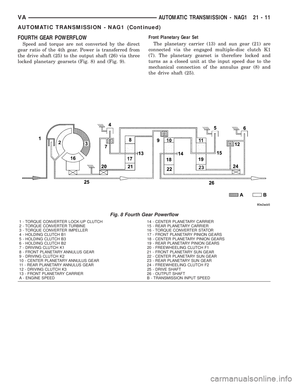
FOURTH GEAR POWERFLOW
Speed and torque are not converted by the direct
gear ratio of the 4th gear. Power is transferred from
the drive shaft (25) to the output shaft (26) via three
locked planetary gearsets (Fig. 8) and (Fig. 9).Front Planetary Gear Set
The planetary carrier (13) and sun gear (21) are
connected via the engaged multiple-disc clutch K1
(7). The planetary gearset is therefore locked and
turns as a closed unit at the input speed due to the
mechanical connection of the annulus gear (8) and
the drive shaft (25).
Fig. 8 Fourth Gear Powerflow
1 - TORQUE CONVERTER LOCK-UP CLUTCH 14 - CENTER PLANETARY CARRIER
2 - TORQUE CONVERTER TURBINE 15 - REAR PLANETARY CARRIER
3 - TORQUE CONVERTER IMPELLER 16 - TORQUE CONVERTER STATOR
4 - HOLDING CLUTCH B1 17 - FRONT PLANETARY PINION GEARS
5 - HOLDING CLUTCH B3 18 - CENTER PLANETARY PINION GEARS
6 - HOLDING CLUTCH B2 19 - REAR PLANETARY PINION GEARS
7 - DRIVING CLUTCH K1 20 - FREEWHEELING CLUTCH F1
8 - FRONT PLANETARY ANNULUS GEAR 21 - FRONT PLANETARY SUN GEAR
9 - DRIVING CLUTCH K2 22 - CENTER PLANETARY SUN GEAR
10 - CENTER PLANETARY ANNULUS GEAR 23 - REAR PLANETARY SUN GEAR
11 - REAR PLANETARY ANNULUS GEAR 24 - FREEWHEELING CLUTCH F2
12 - DRIVING CLUTCH K3 25 - DRIVE SHAFT
13 - FRONT PLANETARY CARRIER 26 - OUTPUT SHAFT
A - ENGINE SPEED B - TRANSMISSION INPUT SPEED
VAAUTOMATIC TRANSMISSION - NAG1 21 - 11
AUTOMATIC TRANSMISSION - NAG1 (Continued)
Page 888 of 1232
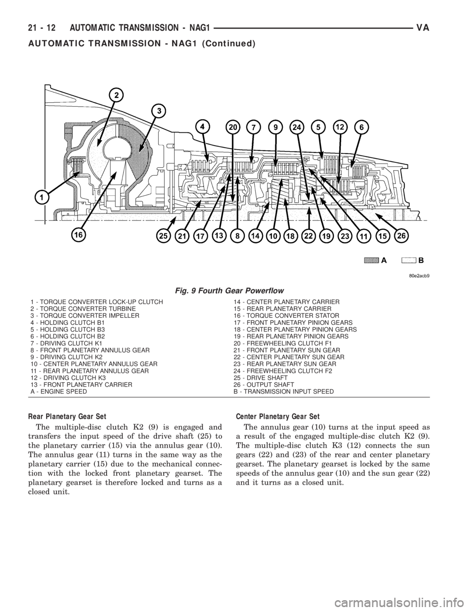
Rear Planetary Gear Set
The multiple-disc clutch K2 (9) is engaged and
transfers the input speed of the drive shaft (25) to
the planetary carrier (15) via the annulus gear (10).
The annulus gear (11) turns in the same way as the
planetary carrier (15) due to the mechanical connec-
tion with the locked front planetary gearset. The
planetary gearset is therefore locked and turns as a
closed unit.Center Planetary Gear Set
The annulus gear (10) turns at the input speed as
a result of the engaged multiple-disc clutch K2 (9).
The multiple-disc clutch K3 (12) connects the sun
gears (22) and (23) of the rear and center planetary
gearset. The planetary gearset is locked by the same
speeds of the annulus gear (10) and the sun gear (22)
and it turns as a closed unit.
Fig. 9 Fourth Gear Powerflow
1 - TORQUE CONVERTER LOCK-UP CLUTCH 14 - CENTER PLANETARY CARRIER
2 - TORQUE CONVERTER TURBINE 15 - REAR PLANETARY CARRIER
3 - TORQUE CONVERTER IMPELLER 16 - TORQUE CONVERTER STATOR
4 - HOLDING CLUTCH B1 17 - FRONT PLANETARY PINION GEARS
5 - HOLDING CLUTCH B3 18 - CENTER PLANETARY PINION GEARS
6 - HOLDING CLUTCH B2 19 - REAR PLANETARY PINION GEARS
7 - DRIVING CLUTCH K1 20 - FREEWHEELING CLUTCH F1
8 - FRONT PLANETARY ANNULUS GEAR 21 - FRONT PLANETARY SUN GEAR
9 - DRIVING CLUTCH K2 22 - CENTER PLANETARY SUN GEAR
10 - CENTER PLANETARY ANNULUS GEAR 23 - REAR PLANETARY SUN GEAR
11 - REAR PLANETARY ANNULUS GEAR 24 - FREEWHEELING CLUTCH F2
12 - DRIVING CLUTCH K3 25 - DRIVE SHAFT
13 - FRONT PLANETARY CARRIER 26 - OUTPUT SHAFT
A - ENGINE SPEED B - TRANSMISSION INPUT SPEED
21 - 12 AUTOMATIC TRANSMISSION - NAG1VA
AUTOMATIC TRANSMISSION - NAG1 (Continued)
Page 889 of 1232
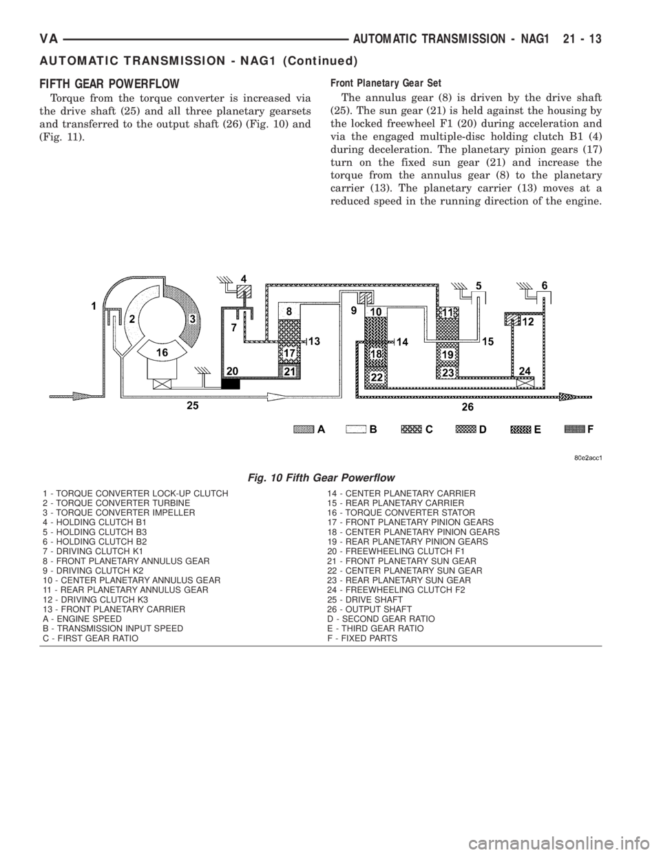
FIFTH GEAR POWERFLOW
Torque from the torque converter is increased via
the drive shaft (25) and all three planetary gearsets
and transferred to the output shaft (26) (Fig. 10) and
(Fig. 11).Front Planetary Gear Set
The annulus gear (8) is driven by the drive shaft
(25). The sun gear (21) is held against the housing by
the locked freewheel F1 (20) during acceleration and
via the engaged multiple-disc holding clutch B1 (4)
during deceleration. The planetary pinion gears (17)
turn on the fixed sun gear (21) and increase the
torque from the annulus gear (8) to the planetary
carrier (13). The planetary carrier (13) moves at a
reduced speed in the running direction of the engine.
Fig. 10 Fifth Gear Powerflow
1 - TORQUE CONVERTER LOCK-UP CLUTCH 14 - CENTER PLANETARY CARRIER
2 - TORQUE CONVERTER TURBINE 15 - REAR PLANETARY CARRIER
3 - TORQUE CONVERTER IMPELLER 16 - TORQUE CONVERTER STATOR
4 - HOLDING CLUTCH B1 17 - FRONT PLANETARY PINION GEARS
5 - HOLDING CLUTCH B3 18 - CENTER PLANETARY PINION GEARS
6 - HOLDING CLUTCH B2 19 - REAR PLANETARY PINION GEARS
7 - DRIVING CLUTCH K1 20 - FREEWHEELING CLUTCH F1
8 - FRONT PLANETARY ANNULUS GEAR 21 - FRONT PLANETARY SUN GEAR
9 - DRIVING CLUTCH K2 22 - CENTER PLANETARY SUN GEAR
10 - CENTER PLANETARY ANNULUS GEAR 23 - REAR PLANETARY SUN GEAR
11 - REAR PLANETARY ANNULUS GEAR 24 - FREEWHEELING CLUTCH F2
12 - DRIVING CLUTCH K3 25 - DRIVE SHAFT
13 - FRONT PLANETARY CARRIER 26 - OUTPUT SHAFT
A - ENGINE SPEED D - SECOND GEAR RATIO
B - TRANSMISSION INPUT SPEED E - THIRD GEAR RATIO
C - FIRST GEAR RATIO F - FIXED PARTS
VAAUTOMATIC TRANSMISSION - NAG1 21 - 13
AUTOMATIC TRANSMISSION - NAG1 (Continued)
Page 890 of 1232
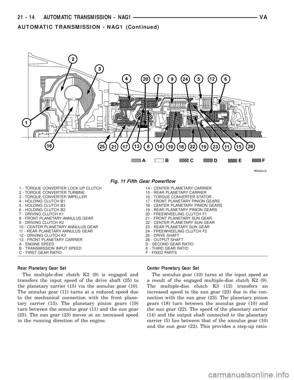
Rear Planetary Gear Set
The multiple-disc clutch K2 (9) is engaged and
transfers the input speed of the drive shaft (25) to
the planetary carrier (15) via the annulus gear (10).
The annulus gear (11) turns at a reduced speed due
to the mechanical connection with the front plane-
tary carrier (13). The planetary pinion gears (19)
turn between the annulus gear (11) and the sun gear
(23). The sun gear (23) moves at an increased speed
in the running direction of the engine.Center Planetary Gear Set
The annulus gear (10) turns at the input speed as
a result of the engaged multiple-disc clutch K2 (9).
The multiple-disc clutch K3 (12) transfers an
increased speed to the sun gear (22) due to the con-
nection with the sun gear (23). The planetary pinion
gears (18) turn between the annulus gear (10) and
the sun gear (22). The speed of the planetary carrier
(14) and the output shaft connected to the planetary
carrier (5) lies between that of the annulus gear (10)
and the sun gear (22). This provides a step-up ratio.
Fig. 11 Fifth Gear Powerflow
1 - TORQUE CONVERTER LOCK-UP CLUTCH 14 - CENTER PLANETARY CARRIER
2 - TORQUE CONVERTER TURBINE 15 - REAR PLANETARY CARRIER
3 - TORQUE CONVERTER IMPELLER 16 - TORQUE CONVERTER STATOR
4 - HOLDING CLUTCH B1 17 - FRONT PLANETARY PINION GEARS
5 - HOLDING CLUTCH B3 18 - CENTER PLANETARY PINION GEARS
6 - HOLDING CLUTCH B2 19 - REAR PLANETARY PINION GEARS
7 - DRIVING CLUTCH K1 20 - FREEWHEELING CLUTCH F1
8 - FRONT PLANETARY ANNULUS GEAR 21 - FRONT PLANETARY SUN GEAR
9 - DRIVING CLUTCH K2 22 - CENTER PLANETARY SUN GEAR
10 - CENTER PLANETARY ANNULUS GEAR 23 - REAR PLANETARY SUN GEAR
11 - REAR PLANETARY ANNULUS GEAR 24 - FREEWHEELING CLUTCH F2
12 - DRIVING CLUTCH K3 25 - DRIVE SHAFT
13 - FRONT PLANETARY CARRIER 26 - OUTPUT SHAFT
A - ENGINE SPEED D - SECOND GEAR RATIO
B - TRANSMISSION INPUT SPEED E - THIRD GEAR RATIO
C - FIRST GEAR RATIO F - FIXED PARTS
21 - 14 AUTOMATIC TRANSMISSION - NAG1VA
AUTOMATIC TRANSMISSION - NAG1 (Continued)
Page 891 of 1232
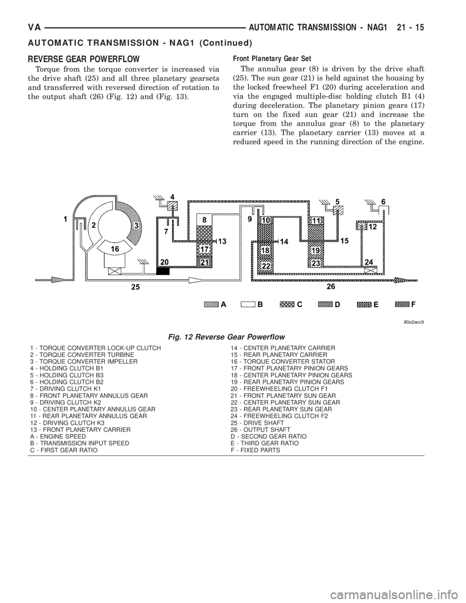
REVERSE GEAR POWERFLOW
Torque from the torque converter is increased via
the drive shaft (25) and all three planetary gearsets
and transferred with reversed direction of rotation to
the output shaft (26) (Fig. 12) and (Fig. 13).Front Planetary Gear Set
The annulus gear (8) is driven by the drive shaft
(25). The sun gear (21) is held against the housing by
the locked freewheel F1 (20) during acceleration and
via the engaged multiple-disc holding clutch B1 (4)
during deceleration. The planetary pinion gears (17)
turn on the fixed sun gear (21) and increase the
torque from the annulus gear (8) to the planetary
carrier (13). The planetary carrier (13) moves at a
reduced speed in the running direction of the engine.
Fig. 12 Reverse Gear Powerflow
1 - TORQUE CONVERTER LOCK-UP CLUTCH 14 - CENTER PLANETARY CARRIER
2 - TORQUE CONVERTER TURBINE 15 - REAR PLANETARY CARRIER
3 - TORQUE CONVERTER IMPELLER 16 - TORQUE CONVERTER STATOR
4 - HOLDING CLUTCH B1 17 - FRONT PLANETARY PINION GEARS
5 - HOLDING CLUTCH B3 18 - CENTER PLANETARY PINION GEARS
6 - HOLDING CLUTCH B2 19 - REAR PLANETARY PINION GEARS
7 - DRIVING CLUTCH K1 20 - FREEWHEELING CLUTCH F1
8 - FRONT PLANETARY ANNULUS GEAR 21 - FRONT PLANETARY SUN GEAR
9 - DRIVING CLUTCH K2 22 - CENTER PLANETARY SUN GEAR
10 - CENTER PLANETARY ANNULUS GEAR 23 - REAR PLANETARY SUN GEAR
11 - REAR PLANETARY ANNULUS GEAR 24 - FREEWHEELING CLUTCH F2
12 - DRIVING CLUTCH K3 25 - DRIVE SHAFT
13 - FRONT PLANETARY CARRIER 26 - OUTPUT SHAFT
A - ENGINE SPEED D - SECOND GEAR RATIO
B - TRANSMISSION INPUT SPEED E - THIRD GEAR RATIO
C - FIRST GEAR RATIO F - FIXED PARTS
VAAUTOMATIC TRANSMISSION - NAG1 21 - 15
AUTOMATIC TRANSMISSION - NAG1 (Continued)
Page 892 of 1232
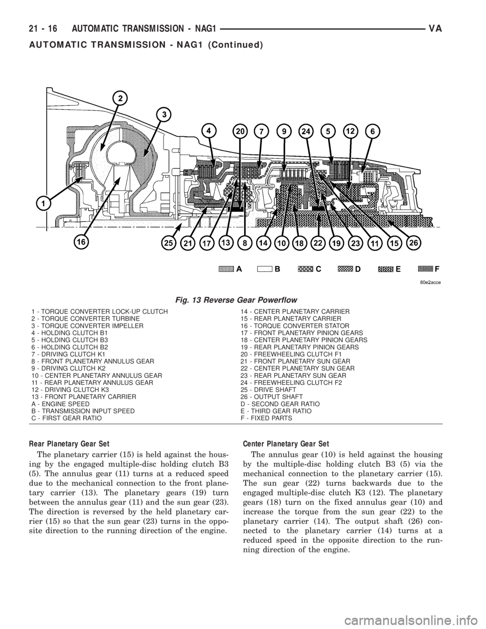
Rear Planetary Gear Set
The planetary carrier (15) is held against the hous-
ing by the engaged multiple-disc holding clutch B3
(5). The annulus gear (11) turns at a reduced speed
due to the mechanical connection to the front plane-
tary carrier (13). The planetary gears (19) turn
between the annulus gear (11) and the sun gear (23).
The direction is reversed by the held planetary car-
rier (15) so that the sun gear (23) turns in the oppo-
site direction to the running direction of the engine.Center Planetary Gear Set
The annulus gear (10) is held against the housing
by the multiple-disc holding clutch B3 (5) via the
mechanical connection to the planetary carrier (15).
The sun gear (22) turns backwards due to the
engaged multiple-disc clutch K3 (12). The planetary
gears (18) turn on the fixed annulus gear (10) and
increase the torque from the sun gear (22) to the
planetary carrier (14). The output shaft (26) con-
nected to the planetary carrier (14) turns at a
reduced speed in the opposite direction to the run-
ning direction of the engine.
Fig. 13 Reverse Gear Powerflow
1 - TORQUE CONVERTER LOCK-UP CLUTCH 14 - CENTER PLANETARY CARRIER
2 - TORQUE CONVERTER TURBINE 15 - REAR PLANETARY CARRIER
3 - TORQUE CONVERTER IMPELLER 16 - TORQUE CONVERTER STATOR
4 - HOLDING CLUTCH B1 17 - FRONT PLANETARY PINION GEARS
5 - HOLDING CLUTCH B3 18 - CENTER PLANETARY PINION GEARS
6 - HOLDING CLUTCH B2 19 - REAR PLANETARY PINION GEARS
7 - DRIVING CLUTCH K1 20 - FREEWHEELING CLUTCH F1
8 - FRONT PLANETARY ANNULUS GEAR 21 - FRONT PLANETARY SUN GEAR
9 - DRIVING CLUTCH K2 22 - CENTER PLANETARY SUN GEAR
10 - CENTER PLANETARY ANNULUS GEAR 23 - REAR PLANETARY SUN GEAR
11 - REAR PLANETARY ANNULUS GEAR 24 - FREEWHEELING CLUTCH F2
12 - DRIVING CLUTCH K3 25 - DRIVE SHAFT
13 - FRONT PLANETARY CARRIER 26 - OUTPUT SHAFT
A - ENGINE SPEED D - SECOND GEAR RATIO
B - TRANSMISSION INPUT SPEED E - THIRD GEAR RATIO
C - FIRST GEAR RATIO F - FIXED PARTS
21 - 16 AUTOMATIC TRANSMISSION - NAG1VA
AUTOMATIC TRANSMISSION - NAG1 (Continued)