2005 MERCEDES-BENZ SPRINTER wheel
[x] Cancel search: wheelPage 706 of 1232
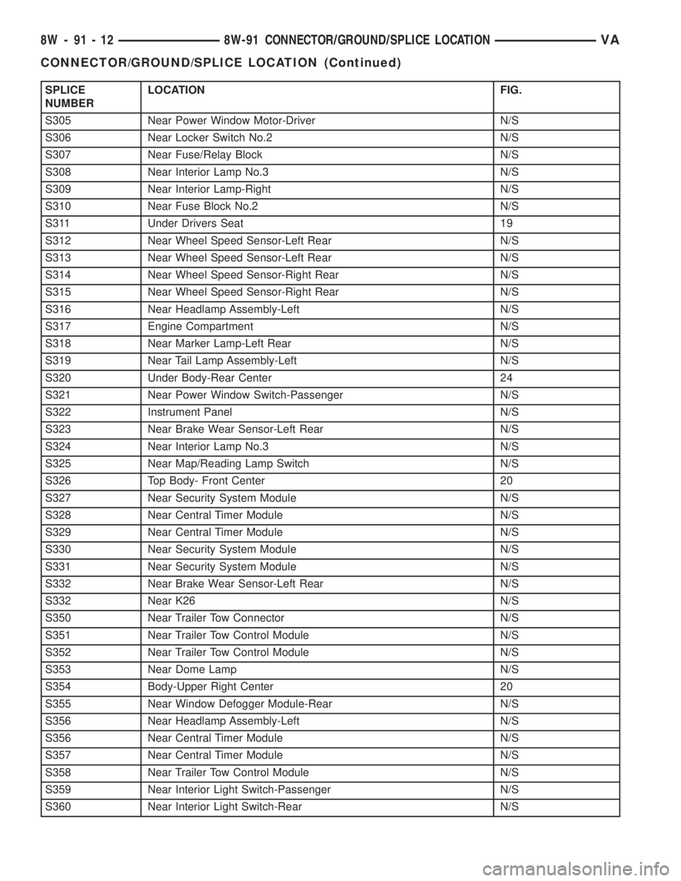
SPLICE
NUMBERLOCATION FIG.
S305 Near Power Window Motor-Driver N/S
S306 Near Locker Switch No.2 N/S
S307 Near Fuse/Relay Block N/S
S308 Near Interior Lamp No.3 N/S
S309 Near Interior Lamp-Right N/S
S310 Near Fuse Block No.2 N/S
S311 Under Drivers Seat 19
S312 Near Wheel Speed Sensor-Left Rear N/S
S313 Near Wheel Speed Sensor-Left Rear N/S
S314 Near Wheel Speed Sensor-Right Rear N/S
S315 Near Wheel Speed Sensor-Right Rear N/S
S316 Near Headlamp Assembly-Left N/S
S317 Engine Compartment N/S
S318 Near Marker Lamp-Left Rear N/S
S319 Near Tail Lamp Assembly-Left N/S
S320 Under Body-Rear Center 24
S321 Near Power Window Switch-Passenger N/S
S322 Instrument Panel N/S
S323 Near Brake Wear Sensor-Left Rear N/S
S324 Near Interior Lamp No.3 N/S
S325 Near Map/Reading Lamp Switch N/S
S326 Top Body- Front Center 20
S327 Near Security System Module N/S
S328 Near Central Timer Module N/S
S329 Near Central Timer Module N/S
S330 Near Security System Module N/S
S331 Near Security System Module N/S
S332 Near Brake Wear Sensor-Left Rear N/S
S332 Near K26 N/S
S350 Near Trailer Tow Connector N/S
S351 Near Trailer Tow Control Module N/S
S352 Near Trailer Tow Control Module N/S
S353 Near Dome Lamp N/S
S354 Body-Upper Right Center 20
S355 Near Window Defogger Module-Rear N/S
S356 Near Headlamp Assembly-Left N/S
S356 Near Central Timer Module N/S
S357 Near Central Timer Module N/S
S358 Near Trailer Tow Control Module N/S
S359 Near Interior Light Switch-Passenger N/S
S360 Near Interior Light Switch-Rear N/S
8W - 91 - 12 8W-91 CONNECTOR/GROUND/SPLICE LOCATIONVA
CONNECTOR/GROUND/SPLICE LOCATION (Continued)
Page 739 of 1232
ENGINE
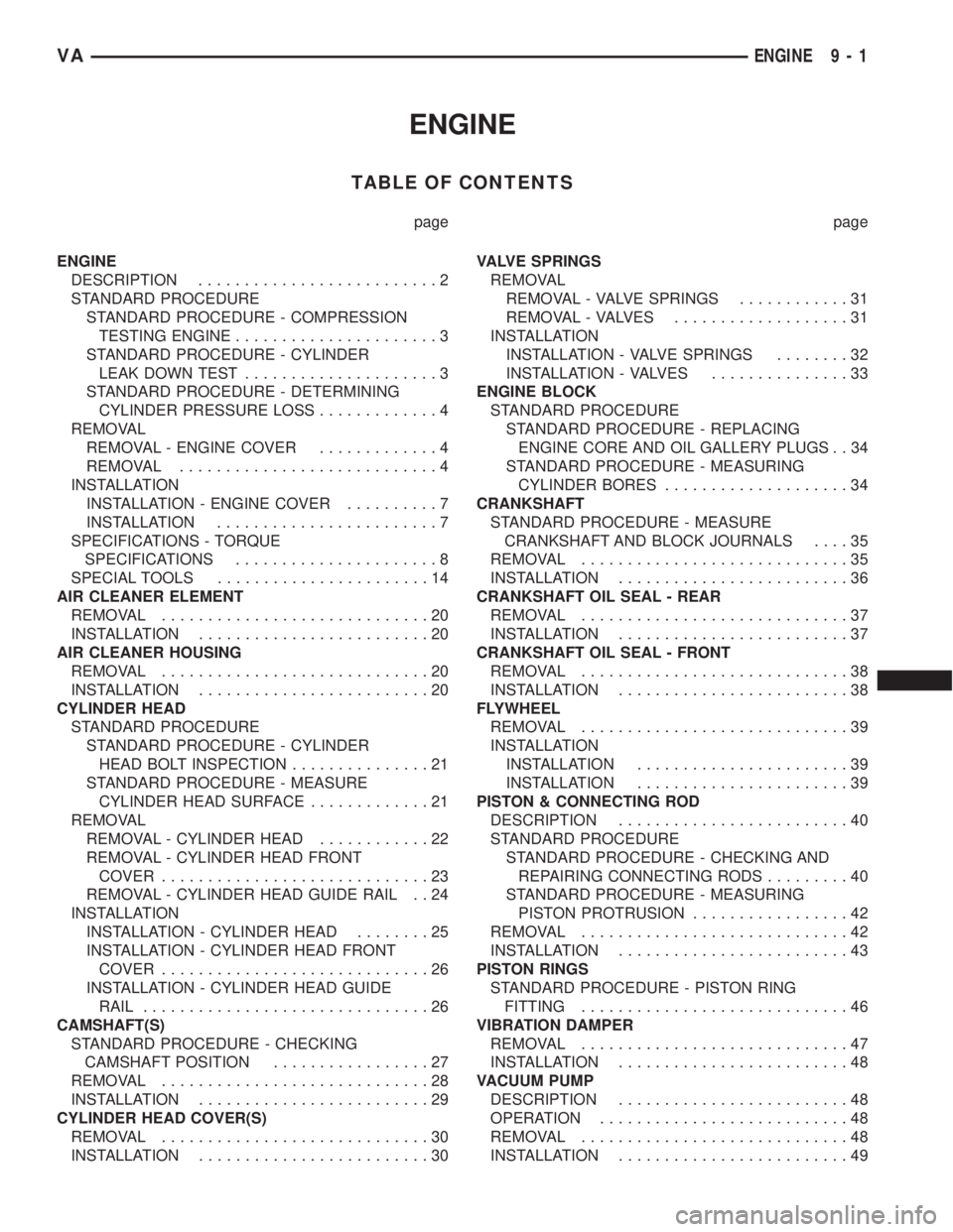
TABLE OF CONTENTS
page page
ENGINE
DESCRIPTION..........................2
STANDARD PROCEDURE
STANDARD PROCEDURE - COMPRESSION
TESTING ENGINE......................3
STANDARD PROCEDURE - CYLINDER
LEAK DOWN TEST.....................3
STANDARD PROCEDURE - DETERMINING
CYLINDER PRESSURE LOSS.............4
REMOVAL
REMOVAL - ENGINE COVER.............4
REMOVAL............................4
INSTALLATION
INSTALLATION - ENGINE COVER..........7
INSTALLATION........................7
SPECIFICATIONS - TORQUE
SPECIFICATIONS......................8
SPECIAL TOOLS.......................14
AIR CLEANER ELEMENT
REMOVAL.............................20
INSTALLATION.........................20
AIR CLEANER HOUSING
REMOVAL.............................20
INSTALLATION.........................20
CYLINDER HEAD
STANDARD PROCEDURE
STANDARD PROCEDURE - CYLINDER
HEAD BOLT INSPECTION...............21
STANDARD PROCEDURE - MEASURE
CYLINDER HEAD SURFACE.............21
REMOVAL
REMOVAL - CYLINDER HEAD............22
REMOVAL - CYLINDER HEAD FRONT
COVER.............................23
REMOVAL - CYLINDER HEAD GUIDE RAIL . . 24
INSTALLATION
INSTALLATION - CYLINDER HEAD........25
INSTALLATION - CYLINDER HEAD FRONT
COVER.............................26
INSTALLATION - CYLINDER HEAD GUIDE
RAIL...............................26
CAMSHAFT(S)
STANDARD PROCEDURE - CHECKING
CAMSHAFT POSITION.................27
REMOVAL.............................28
INSTALLATION.........................29
CYLINDER HEAD COVER(S)
REMOVAL.............................30
INSTALLATION.........................30VALVE SPRINGS
REMOVAL
REMOVAL - VALVE SPRINGS............31
REMOVAL - VALVES...................31
INSTALLATION
INSTALLATION - VALVE SPRINGS........32
INSTALLATION - VALVES...............33
ENGINE BLOCK
STANDARD PROCEDURE
STANDARD PROCEDURE - REPLACING
ENGINE CORE AND OIL GALLERY PLUGS . . 34
STANDARD PROCEDURE - MEASURING
CYLINDER BORES....................34
CRANKSHAFT
STANDARD PROCEDURE - MEASURE
CRANKSHAFT AND BLOCK JOURNALS....35
REMOVAL.............................35
INSTALLATION.........................36
CRANKSHAFT OIL SEAL - REAR
REMOVAL.............................37
INSTALLATION.........................37
CRANKSHAFT OIL SEAL - FRONT
REMOVAL.............................38
INSTALLATION.........................38
FLYWHEEL
REMOVAL.............................39
INSTALLATION
INSTALLATION.......................39
INSTALLATION.......................39
PISTON & CONNECTING ROD
DESCRIPTION.........................40
STANDARD PROCEDURE
STANDARD PROCEDURE - CHECKING AND
REPAIRING CONNECTING RODS.........40
STANDARD PROCEDURE - MEASURING
PISTON PROTRUSION.................42
REMOVAL.............................42
INSTALLATION.........................43
PISTON RINGS
STANDARD PROCEDURE - PISTON RING
FITTING.............................46
VIBRATION DAMPER
REMOVAL.............................47
INSTALLATION.........................48
VACUUM PUMP
DESCRIPTION.........................48
OPERATION...........................48
REMOVAL.............................48
INSTALLATION.........................49
VAENGINE 9 - 1
Page 747 of 1232
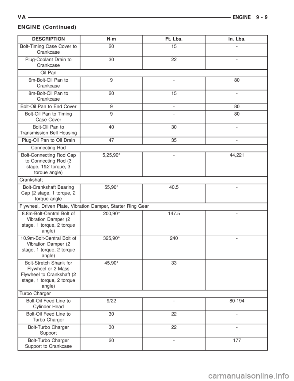
DESCRIPTION N´m Ft. Lbs. In. Lbs.
Bolt-Timing Case Cover to
Crankcase20 15 -
Plug-Coolant Drain to
Crankcase30 22 -
Oil Pan
6m-Bolt-Oil Pan to
Crankcase9-80
8m-Bolt-Oil Pan to
Crankcase20 15 -
Bolt-Oil Pan to End Cover 9 - 80
Bolt-Oil Pan to Timing
Case Cover9-80
Bolt-Oil Pan to
Transmission Bell Housing40 30 -
Plug-Oil Pan to Oil Drain 47 35 -
Connecting Rod
Bolt-Connecting Rod Cap
to Connecting Rod (3
stage, 1&2 torque, 3
torque angle)5,25,90É - 44,221
Crankshaft
Bolt-Crankshaft Bearing
Cap (2 stage, 1 torque, 2
torque angle55,90É 40.5 -
Flywheel, Driven Plate, Vibration Damper, Starter Ring Gear
8.8m-Bolt-Central Bolt of
Vibration Damper (2
stage, 1 torque, 2 torque
angle)200,90É 147.5 -
10.9m-Bolt-Central Bolt of
Vibration Damper (2
stage, 1 torque, 2 torque
angle)325,90É 240 -
Bolt-Stretch Shank for
Flywheel or 2 Mass
Flywheel to Crankshaft (2
stage, 1 torque, 2 torque
angle)45,90É 33
Turbo Charger
Bolt-Oil Feed Line to
Cylinder Head9/22 - 80-194
Bolt-Oil Feed Line to
Turbo Charger30 22 -
Bolt-Turbo Charger
Support30 22 -
Bolt-Turbo Charger
Support to Crankcase20 - 177
VAENGINE 9 - 9
ENGINE (Continued)
Page 758 of 1232
AIR CLEANER ELEMENT
REMOVAL
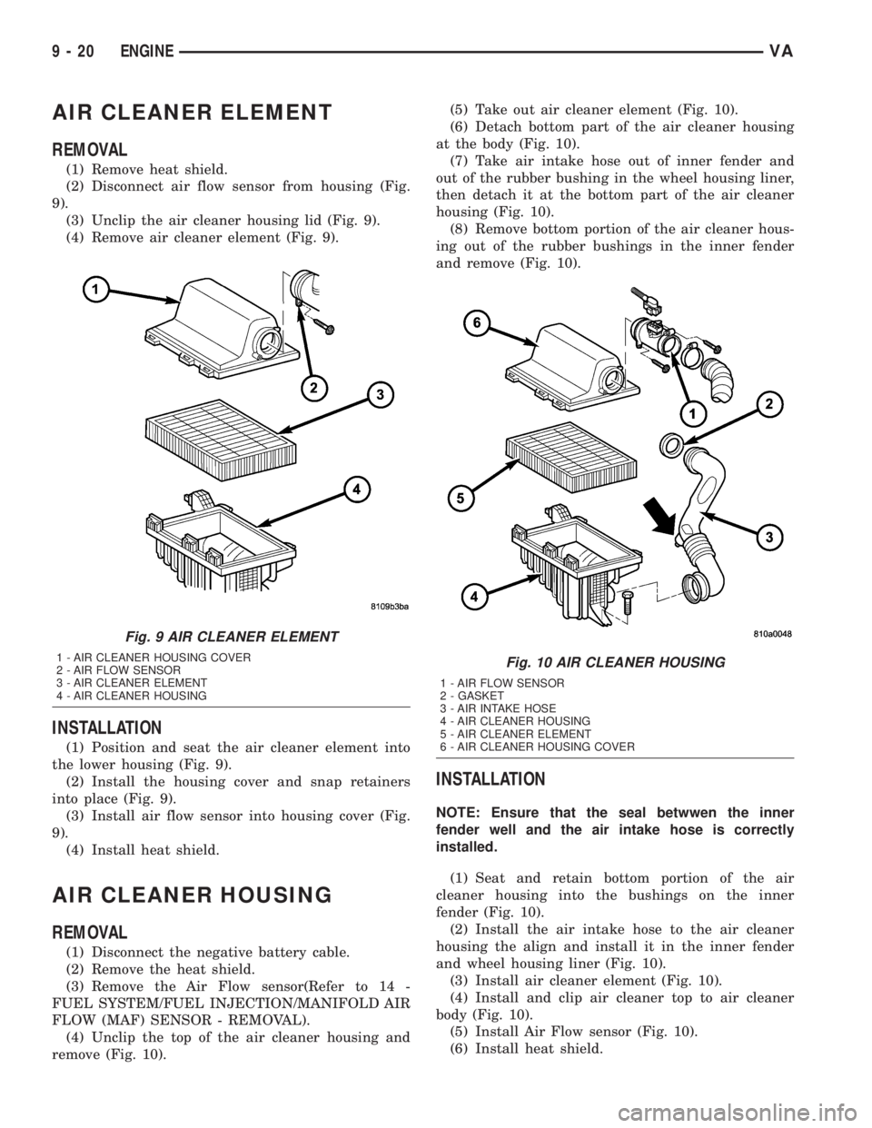
(1) Remove heat shield.
(2) Disconnect air flow sensor from housing (Fig.
9).
(3) Unclip the air cleaner housing lid (Fig. 9).
(4) Remove air cleaner element (Fig. 9).
INSTALLATION
(1) Position and seat the air cleaner element into
the lower housing (Fig. 9).
(2) Install the housing cover and snap retainers
into place (Fig. 9).
(3) Install air flow sensor into housing cover (Fig.
9).
(4) Install heat shield.
AIR CLEANER HOUSING
REMOVAL
(1) Disconnect the negative battery cable.
(2) Remove the heat shield.
(3) Remove the Air Flow sensor(Refer to 14 -
FUEL SYSTEM/FUEL INJECTION/MANIFOLD AIR
FLOW (MAF) SENSOR - REMOVAL).
(4) Unclip the top of the air cleaner housing and
remove (Fig. 10).(5) Take out air cleaner element (Fig. 10).
(6) Detach bottom part of the air cleaner housing
at the body (Fig. 10).
(7) Take air intake hose out of inner fender and
out of the rubber bushing in the wheel housing liner,
then detach it at the bottom part of the air cleaner
housing (Fig. 10).
(8) Remove bottom portion of the air cleaner hous-
ing out of the rubber bushings in the inner fender
and remove (Fig. 10).
INSTALLATION
NOTE: Ensure that the seal betwwen the inner
fender well and the air intake hose is correctly
installed.
(1) Seat and retain bottom portion of the air
cleaner housing into the bushings on the inner
fender (Fig. 10).
(2) Install the air intake hose to the air cleaner
housing the align and install it in the inner fender
and wheel housing liner (Fig. 10).
(3) Install air cleaner element (Fig. 10).
(4) Install and clip air cleaner top to air cleaner
body (Fig. 10).
(5) Install Air Flow sensor (Fig. 10).
(6) Install heat shield.
Fig. 9 AIR CLEANER ELEMENT
1 - AIR CLEANER HOUSING COVER
2 - AIR FLOW SENSOR
3 - AIR CLEANER ELEMENT
4 - AIR CLEANER HOUSINGFig. 10 AIR CLEANER HOUSING
1 - AIR FLOW SENSOR
2 - GASKET
3 - AIR INTAKE HOSE
4 - AIR CLEANER HOUSING
5 - AIR CLEANER ELEMENT
6 - AIR CLEANER HOUSING COVER
9 - 20 ENGINEVA
Page 775 of 1232
CRANKSHAFT OIL SEAL -
REAR
REMOVAL
This must be done with the transmission removed
from the vehicle.
(1) Disconnect the negative battery cable.
(2) Raise and support the vehicle.
(3) Drain the engine oil.
NOTE: Loosen all of the oil pan bolts to assure that
the oil pan gasket is not damaged when removing
the rear main oil seal and end cover assembly.
NOTE: Inspect the oil pan gasket for damage. If the
oil pan gasket is damaged, remove the oil pan and
replace the oil pan gasket.
(4) Loosen the oil pan bolts.
(5) Remove the flywheel.CAUTION: Care must be taken when removing the
rear main seal and adaptor assembly. Failure to do
so will result in damage to the oil pan gasket.
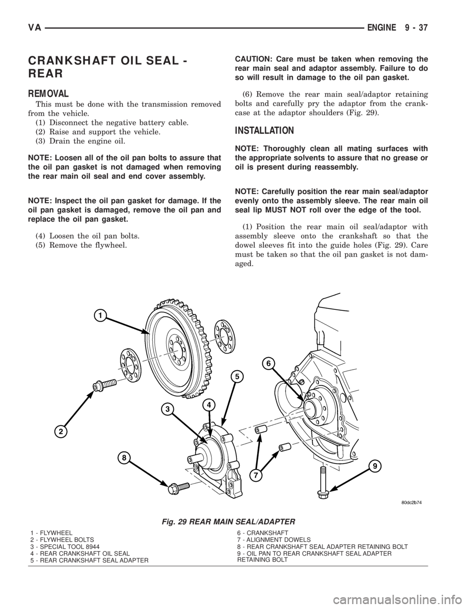
(6) Remove the rear main seal/adaptor retaining
bolts and carefully pry the adaptor from the crank-
case at the adaptor shoulders (Fig. 29).
INSTALLATION
NOTE: Thoroughly clean all mating surfaces with
the appropriate solvents to assure that no grease or
oil is present during reassembly.
NOTE: Carefully position the rear main seal/adaptor
evenly onto the assembly sleeve. The rear main oil
seal lip MUST NOT roll over the edge of the tool.
(1) Position the rear main oil seal/adaptor with
assembly sleeve onto the crankshaft so that the
dowel sleeves fit into the guide holes (Fig. 29). Care
must be taken so that the oil pan gasket is not dam-
aged.
Fig. 29 REAR MAIN SEAL/ADAPTER
1 - FLYWHEEL
2 - FLYWHEEL BOLTS
3 - SPECIAL TOOL 8944
4 - REAR CRANKSHAFT OIL SEAL
5 - REAR CRANKSHAFT SEAL ADAPTER6 - CRANKSHAFT
7 - ALIGNMENT DOWELS
8 - REAR CRANKSHAFT SEAL ADAPTER RETAINING BOLT
9 - OIL PAN TO REAR CRANKSHAFT SEAL ADAPTER
RETAINING BOLT
VAENGINE 9 - 37
Page 776 of 1232
(2) Install the rear main seal/adaptor to crankcase
bolts and tighten to 9´Nm (80 lbs.in) (Fig. 29).
(3) Tighten the M6 oil pan bolts to 9N´m (80 lbs
in) and the M8 bolts to 20 N´m (15 lbs ft).
(4) Install the fly wheel and tighten bolts in two
stages (Fig. 29). 45N´m (33 lbs. ft.) then 90É.
(5) Install the oil pan drain plug and tighten to
25N´m (18 lbs ft).
(6) Lower the vehicle.
(7) Fill the crankcase with the correct engine oil,
to the proper level. Refer to owners manual for spec-
ifications.
(8) Connect the negative battery cable.
WARNING: USE EXTREME CAUTION WHEN THE
ENGINE IS OPERATING. DO NOT PUT YOUR
HANDS NEAR THE PULLEYS, BELTS OR FAN. DO
NOT WEAR LOOSE CLOTHES.
(9) Start the engine and inspect for leaks.
CRANKSHAFT OIL SEAL -
FRONT
REMOVAL
(1) Disconnect the negative battery cable.
(2) Remove the accessory drive belt.
(3) Install the retaining lock for the crankshaft/
ring gear.
NOTE: If the hub of the belt pulley/vibration damper
is tight, use a puller to remove it. Do Not tilt the
puller. The groves of the puller MUST mesh fully
into the slots of the belt pulley.
NOTE: Inspect the running surface of the belt pulley
for wear.
(4) Remove the belt pully/vibration damper.
CAUTION: Care must be taken to prevent severe
damage to the crankshaft and mounting whole for
the front crankshaft seal.
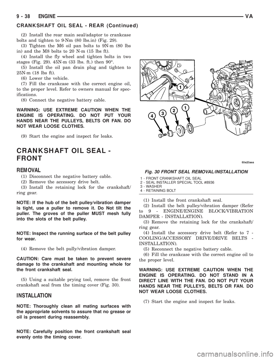
(5) Using a suitable prying tool, remove the front
crankshaft seal from the timing cover (Fig. 30).
INSTALLATION
NOTE: Thoroughly clean all mating surfaces with
the appropriate solvents to assure that no grease or
oil is present during reassembly.
NOTE: Carefully position the front crankshaft seal
evenly onto the timing cover.(1) Install the front crankshaft seal.
(2) Install the belt pulley/vibration damper (Refer
to 9 - ENGINE/ENGINE BLOCK/VIBRATION
DAMPER - INSTALLATION).
(3) Remove the retaining lock for the crankshaft/
ring gear.
(4) Install the accessory drive belt (Refer to 7 -
COOLING/ACCESSORY DRIVE/DRIVE BELTS -
INSTALLATION).
(5) Reconnect the negative battery cable.
(6) Fill the crankcase with the correct engine oil to
the proper level.
WARNING: USE EXTREME CAUTION WHEN THE
ENGINE IS OPERATING. DO NOT STAND IN A
DIRECT LINE WITH THE FAN. DO NOT PUT YOUR
HANDS NEAR THE PULLEYS, BELTS OR FAN. DO
NOT WEAR LOOSE CLOTHES.
(7) Start the engine and inspect for leaks.
Fig. 30 FRONT SEAL REMOVAL/INSTALLATION
1 - FRONT CRANKSHAFT OIL SEAL
2 - SEAL INSTALLER SPECIAL TOOL #8936
3 - WASHER
4 - RETAINING BOLT
9 - 38 ENGINEVA
CRANKSHAFT OIL SEAL - REAR (Continued)
Page 777 of 1232
FLYWHEEL
REMOVAL
(1) Remove transmission (Refer to 21 - TRANS-
MISSION/TRANSAXLE/AUTOMATIC - W5J400 -
REMOVAL).
NOTE: M6x90 bolts must be used with retaining
lock to prevent damage to rear end cover.
(2) Install retaining lock for crankshaft/starter
ring gear.
NOTE: Flywheel does not need balancing or should
it be interchanged.
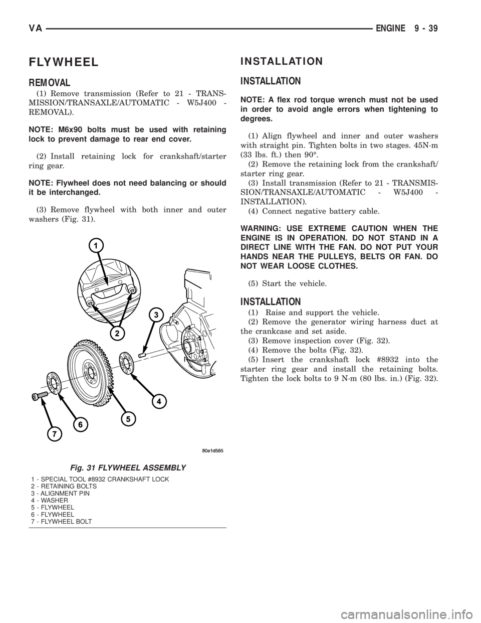
(3) Remove flywheel with both inner and outer
washers (Fig. 31).
INSTALLATION
INSTALLATION
NOTE: A flex rod torque wrench must not be used
in order to avoid angle errors when tightening to
degrees.
(1) Align flywheel and inner and outer washers
with straight pin. Tighten bolts in two stages. 45N´m
(33 lbs. ft.) then 90É.
(2) Remove the retaining lock from the crankshaft/
starter ring gear.
(3) Install transmission (Refer to 21 - TRANSMIS-
SION/TRANSAXLE/AUTOMATIC - W5J400 -
INSTALLATION).
(4) Connect negative battery cable.
WARNING: USE EXTREME CAUTION WHEN THE
ENGINE IS IN OPERATION. DO NOT STAND IN A
DIRECT LINE WITH THE FAN. DO NOT PUT YOUR
HANDS NEAR THE PULLEYS, BELTS OR FAN. DO
NOT WEAR LOOSE CLOTHES.
(5) Start the vehicle.
INSTALLATION
(1) Raise and support the vehicle.
(2) Remove the generator wiring harness duct at
the crankcase and set aside.
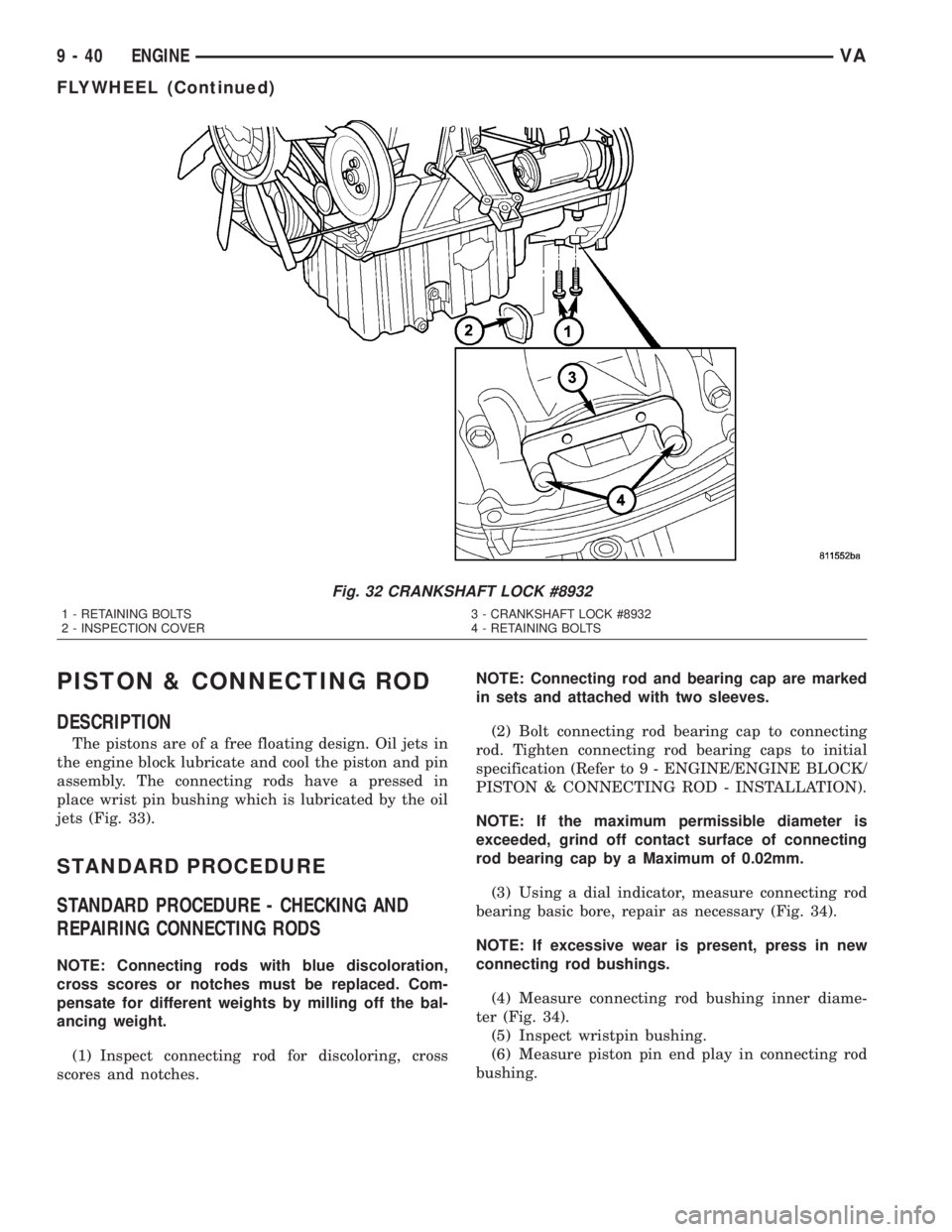
(3) Remove inspection cover (Fig. 32).
(4) Remove the bolts (Fig. 32).
(5) Insert the crankshaft lock #8932 into the
starter ring gear and install the retaining bolts.
Tighten the lock bolts to 9 N´m (80 lbs. in.) (Fig. 32).
Fig. 31 FLYWHEEL ASSEMBLY
1 - SPECIAL TOOL #8932 CRANKSHAFT LOCK
2 - RETAINING BOLTS
3 - ALIGNMENT PIN
4 - WASHER
5 - FLYWHEEL
6 - FLYWHEEL
7 - FLYWHEEL BOLT
VAENGINE 9 - 39
Page 778 of 1232
PISTON & CONNECTING ROD
DESCRIPTION
The pistons are of a free floating design. Oil jets in
the engine block lubricate and cool the piston and pin
assembly. The connecting rods have a pressed in
place wrist pin bushing which is lubricated by the oil
jets (Fig. 33).
STANDARD PROCEDURE
STANDARD PROCEDURE - CHECKING AND
REPAIRING CONNECTING RODS
NOTE: Connecting rods with blue discoloration,
cross scores or notches must be replaced. Com-
pensate for different weights by milling off the bal-
ancing weight.
(1) Inspect connecting rod for discoloring, cross
scores and notches.NOTE: Connecting rod and bearing cap are marked
in sets and attached with two sleeves.
(2) Bolt connecting rod bearing cap to connecting
rod. Tighten connecting rod bearing caps to initial
specification (Refer to 9 - ENGINE/ENGINE BLOCK/
PISTON & CONNECTING ROD - INSTALLATION).
NOTE: If the maximum permissible diameter is
exceeded, grind off contact surface of connecting
rod bearing cap by a Maximum of 0.02mm.
(3) Using a dial indicator, measure connecting rod
bearing basic bore, repair as necessary (Fig. 34).
NOTE: If excessive wear is present, press in new
connecting rod bushings.
(4) Measure connecting rod bushing inner diame-
ter (Fig. 34).
(5) Inspect wristpin bushing.
(6) Measure piston pin end play in connecting rod
bushing.
Fig. 32 CRANKSHAFT LOCK #8932
1 - RETAINING BOLTS 3 - CRANKSHAFT LOCK #8932
2 - INSPECTION COVER 4 - RETAINING BOLTS
9 - 40 ENGINEVA
FLYWHEEL (Continued)