2005 MERCEDES-BENZ SPRINTER wheel
[x] Cancel search: wheelPage 293 of 1232
(3) Using hand pressure, press firmly and evenly
on the washer pump until the inlet nipple is fully
seated in the rubber grommet seal in the washer res-
ervoir mounting hole (Fig. 10).
(4)
If the vehicle is so equipped, reconnect the
washer fluid level switch vent hose to the barbed vent
nipple at the top of the washer pump/motor housing.
(5) Reconnect the washer hose to the barbed outlet
nipple of the washer pump.
(6) Reconnect the vehicle wire harness connector
for the washer pump/motor unit to the motor connec-
tor receptacle.
(7) Refill the washer reservoir with the washer
fluid drained from the reservoir during the removal
procedure.
WASHER RESERVOIR
DESCRIPTION
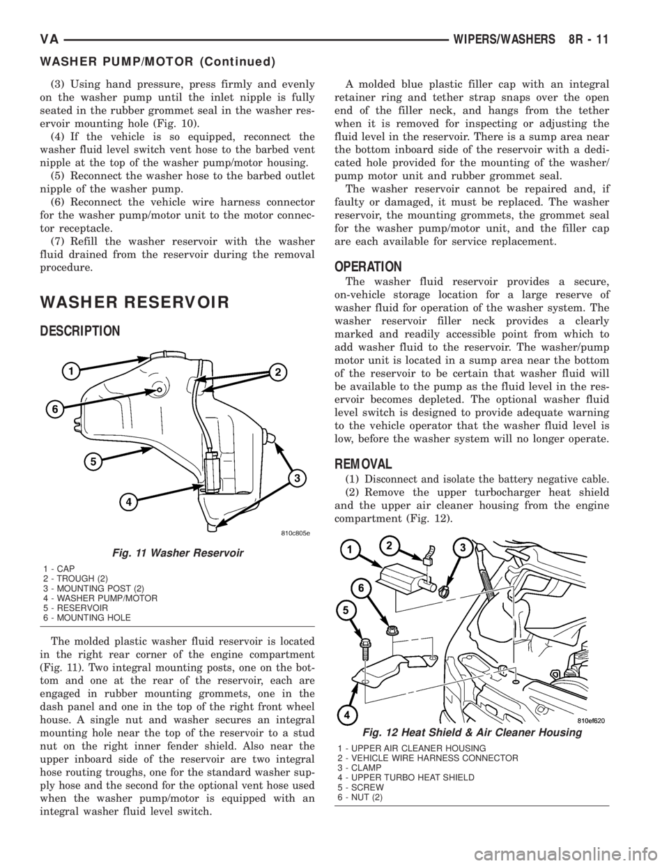
The molded plastic washer fluid reservoir is located
in the right rear corner of the engine compartment
(Fig. 11). Two integral mounting posts, one on the bot-
tom and one at the rear of the reservoir, each are
engaged in rubber mounting grommets, one in the
dash panel and one in the top of the right front wheel
house. A single nut and washer secures an integral
mounting hole near the top of the reservoir to a stud
nut on the right inner fender shield. Also near the
upper inboard side of the reservoir are two integral
hose routing troughs, one for the standard washer sup-
ply hose and the second for the optional vent hose used
when the washer pump/motor is equipped with an
integral washer fluid level switch.
A molded blue plastic filler cap with an integral
retainer ring and tether strap snaps over the open
end of the filler neck, and hangs from the tether
when it is removed for inspecting or adjusting the
fluid level in the reservoir. There is a sump area near
the bottom inboard side of the reservoir with a dedi-
cated hole provided for the mounting of the washer/
pump motor unit and rubber grommet seal.
The washer reservoir cannot be repaired and, if
faulty or damaged, it must be replaced. The washer
reservoir, the mounting grommets, the grommet seal
for the washer pump/motor unit, and the filler cap
are each available for service replacement.
OPERATION
The washer fluid reservoir provides a secure,
on-vehicle storage location for a large reserve of
washer fluid for operation of the washer system. The
washer reservoir filler neck provides a clearly
marked and readily accessible point from which to
add washer fluid to the reservoir. The washer/pump
motor unit is located in a sump area near the bottom
of the reservoir to be certain that washer fluid will
be available to the pump as the fluid level in the res-
ervoir becomes depleted. The optional washer fluid
level switch is designed to provide adequate warning
to the vehicle operator that the washer fluid level is
low, before the washer system will no longer operate.
REMOVAL
(1)Disconnect and isolate the battery negative cable.
(2) Remove the upper turbocharger heat shield
and the upper air cleaner housing from the engine
compartment (Fig. 12).
Fig. 11 Washer Reservoir
1 - CAP
2 - TROUGH (2)
3 - MOUNTING POST (2)
4 - WASHER PUMP/MOTOR
5 - RESERVOIR
6 - MOUNTING HOLE
Fig. 12 Heat Shield & Air Cleaner Housing
1 - UPPER AIR CLEANER HOUSING
2 - VEHICLE WIRE HARNESS CONNECTOR
3 - CLAMP
4 - UPPER TURBO HEAT SHIELD
5 - SCREW
6 - NUT (2)
VAWIPERS/WASHERS 8R - 11
WASHER PUMP/MOTOR (Continued)
Page 294 of 1232
(3) Disconnect the vehicle wire harness connector
for the washer pump/motor unit from the motor con-
nector receptacle.
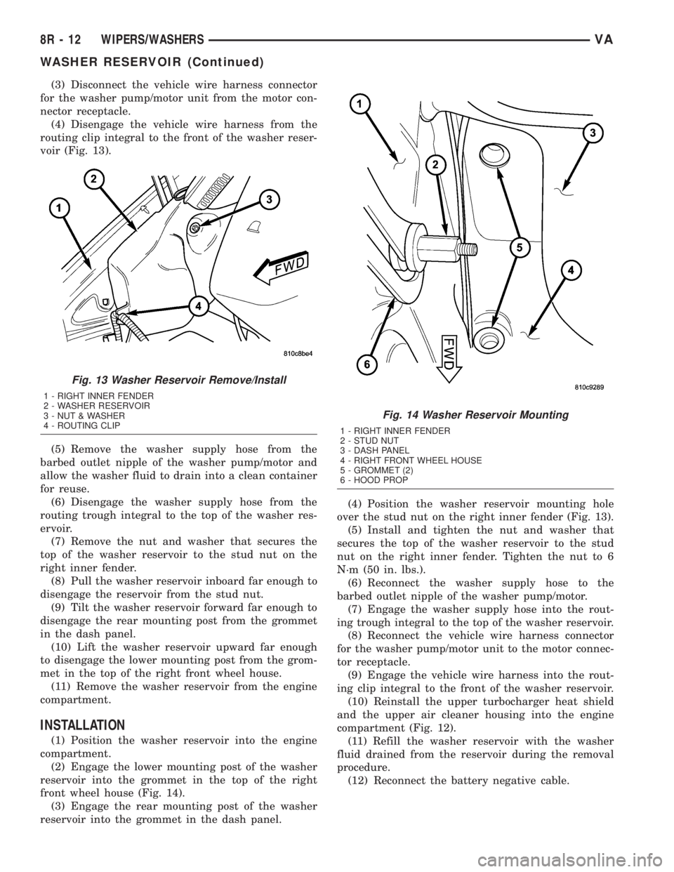
(4) Disengage the vehicle wire harness from the
routing clip integral to the front of the washer reser-
voir (Fig. 13).
(5) Remove the washer supply hose from the
barbed outlet nipple of the washer pump/motor and
allow the washer fluid to drain into a clean container
for reuse.
(6) Disengage the washer supply hose from the
routing trough integral to the top of the washer res-
ervoir.
(7) Remove the nut and washer that secures the
top of the washer reservoir to the stud nut on the
right inner fender.
(8) Pull the washer reservoir inboard far enough to
disengage the reservoir from the stud nut.
(9) Tilt the washer reservoir forward far enough to
disengage the rear mounting post from the grommet
in the dash panel.
(10) Lift the washer reservoir upward far enough
to disengage the lower mounting post from the grom-
met in the top of the right front wheel house.
(11) Remove the washer reservoir from the engine
compartment.
INSTALLATION
(1) Position the washer reservoir into the engine
compartment.
(2) Engage the lower mounting post of the washer
reservoir into the grommet in the top of the right
front wheel house (Fig. 14).
(3) Engage the rear mounting post of the washer
reservoir into the grommet in the dash panel.(4) Position the washer reservoir mounting hole
over the stud nut on the right inner fender (Fig. 13).
(5) Install and tighten the nut and washer that
secures the top of the washer reservoir to the stud
nut on the right inner fender. Tighten the nut to 6
N´m (50 in. lbs.).
(6) Reconnect the washer supply hose to the
barbed outlet nipple of the washer pump/motor.
(7) Engage the washer supply hose into the rout-
ing trough integral to the top of the washer reservoir.
(8) Reconnect the vehicle wire harness connector
for the washer pump/motor unit to the motor connec-
tor receptacle.
(9) Engage the vehicle wire harness into the rout-
ing clip integral to the front of the washer reservoir.
(10) Reinstall the upper turbocharger heat shield
and the upper air cleaner housing into the engine
compartment (Fig. 12).
(11) Refill the washer reservoir with the washer
fluid drained from the reservoir during the removal
procedure.
(12) Reconnect the battery negative cable.
Fig. 13 Washer Reservoir Remove/Install
1 - RIGHT INNER FENDER
2 - WASHER RESERVOIR
3 - NUT & WASHER
4 - ROUTING CLIP
Fig. 14 Washer Reservoir Mounting
1 - RIGHT INNER FENDER
2 - STUD NUT
3 - DASH PANEL
4 - RIGHT FRONT WHEEL HOUSE
5 - GROMMET (2)
6 - HOOD PROP
8R - 12 WIPERS/WASHERSVA
WASHER RESERVOIR (Continued)
Page 304 of 1232
REMOVAL
WARNING: ON VEHICLES EQUIPPED WITH AIR-
BAGS, DISABLE THE SUPPLEMENTAL RESTRAINT
SYSTEM BEFORE ATTEMPTING ANY STEERING
WHEEL, STEERING COLUMN, DRIVER AIRBAG,
PASSENGER AIRBAG, SEAT BELT TENSIONER, OR
INSTRUMENT PANEL COMPONENT DIAGNOSIS OR
SERVICE. DISCONNECT AND ISOLATE THE BAT-
TERY NEGATIVE (GROUND) CABLE, THEN WAIT
TWO MINUTES FOR THE SYSTEM CAPACITOR TO
DISCHARGE BEFORE PERFORMING FURTHER
DIAGNOSIS OR SERVICE. THIS IS THE ONLY SURE
WAY TO DISABLE THE SUPPLEMENTAL
RESTRAINT SYSTEM. FAILURE TO TAKE THE
PROPER PRECAUTIONS COULD RESULT IN ACCI-
DENTAL AIRBAG DEPLOYMENT AND POSSIBLE
PERSONAL INJURY.
(1) Disconnect and isolate the battery negative
cable.
(2) Remove the fuse access panel from the steering
column opening cover below the steering column on
the instrument panel.
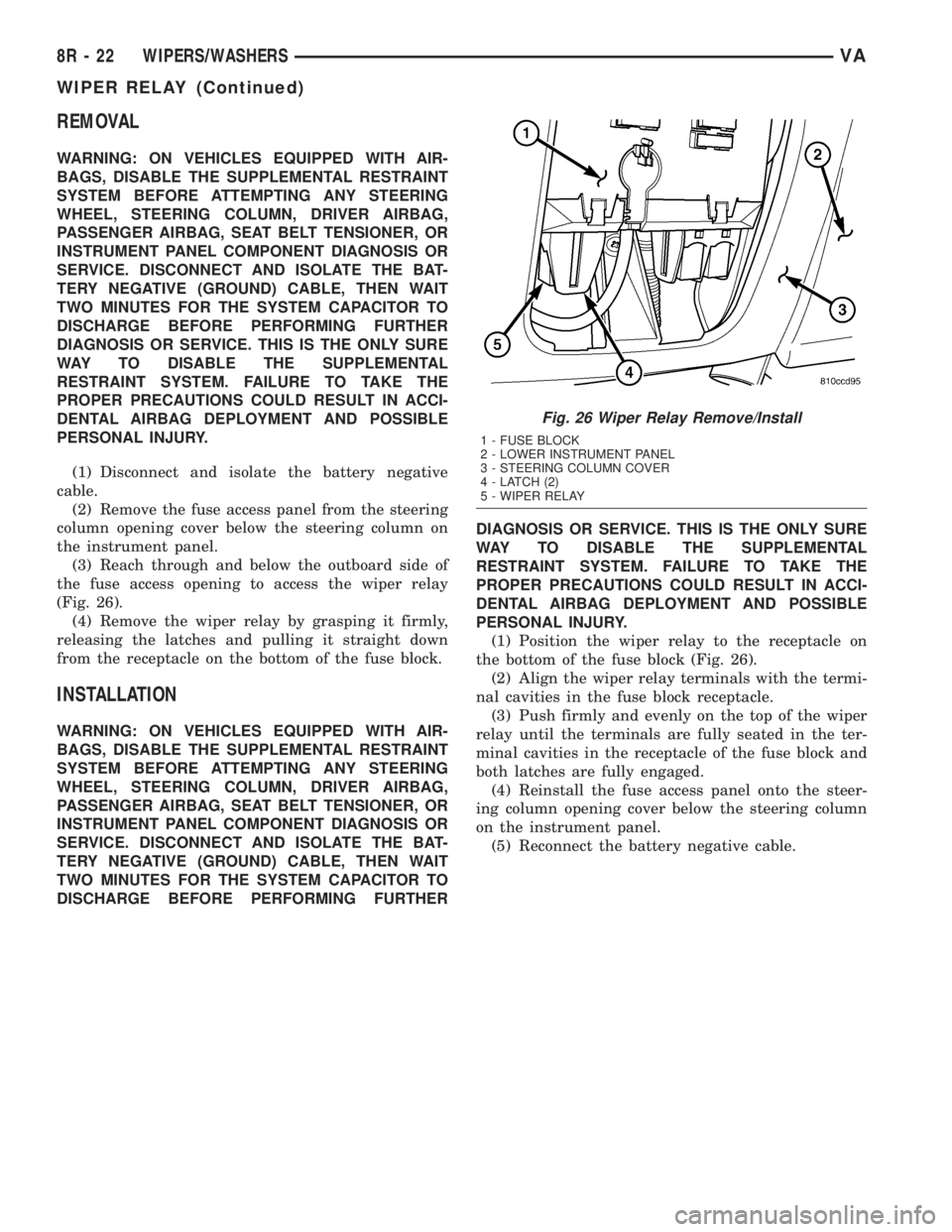
(3) Reach through and below the outboard side of
the fuse access opening to access the wiper relay
(Fig. 26).
(4) Remove the wiper relay by grasping it firmly,
releasing the latches and pulling it straight down
from the receptacle on the bottom of the fuse block.
INSTALLATION
WARNING: ON VEHICLES EQUIPPED WITH AIR-
BAGS, DISABLE THE SUPPLEMENTAL RESTRAINT
SYSTEM BEFORE ATTEMPTING ANY STEERING
WHEEL, STEERING COLUMN, DRIVER AIRBAG,
PASSENGER AIRBAG, SEAT BELT TENSIONER, OR
INSTRUMENT PANEL COMPONENT DIAGNOSIS OR
SERVICE. DISCONNECT AND ISOLATE THE BAT-
TERY NEGATIVE (GROUND) CABLE, THEN WAIT
TWO MINUTES FOR THE SYSTEM CAPACITOR TO
DISCHARGE BEFORE PERFORMING FURTHERDIAGNOSIS OR SERVICE. THIS IS THE ONLY SURE
WAY TO DISABLE THE SUPPLEMENTAL
RESTRAINT SYSTEM. FAILURE TO TAKE THE
PROPER PRECAUTIONS COULD RESULT IN ACCI-
DENTAL AIRBAG DEPLOYMENT AND POSSIBLE
PERSONAL INJURY.
(1) Position the wiper relay to the receptacle on
the bottom of the fuse block (Fig. 26).
(2) Align the wiper relay terminals with the termi-
nal cavities in the fuse block receptacle.
(3) Push firmly and evenly on the top of the wiper
relay until the terminals are fully seated in the ter-
minal cavities in the receptacle of the fuse block and
both latches are fully engaged.
(4) Reinstall the fuse access panel onto the steer-
ing column opening cover below the steering column
on the instrument panel.
(5) Reconnect the battery negative cable.
Fig. 26 Wiper Relay Remove/Install
1 - FUSE BLOCK
2 - LOWER INSTRUMENT PANEL
3 - STEERING COLUMN COVER
4 - LATCH (2)
5 - WIPER RELAY
8R - 22 WIPERS/WASHERSVA
WIPER RELAY (Continued)
Page 311 of 1232
TERMINOLOGY
This is a list of terms and definitions used in the
wiring diagrams.
LHD.................Left Hand Drive Vehicles
RHD ...............Right Hand Drive Vehicles
ATX . . Automatic Transmissions-Front Wheel Drive
MTX . . . Manual Transmissions-Front Wheel Drive
AT....Automatic Transmissions-Rear Wheel Drive
MT .....Manual Transmissions-Rear Wheel Drive
SOHC...........Single Over Head Cam Engine
DOHC..........Double Over Head Cam Engine
Built-Up-Export....... Vehicles Built For Sale In
Markets Other Than North America
Except Built-Up-Export . Vehicles Built For Sale In
North America
DESCRIPTION - CIRCUIT INFORMATION
Each wire shown in the diagrams contains a code
which identifies gage of wire, and color.
WIRE COLOR CODE CHART
COLOR CODE COLOR
BL BLUE
BK BLACK
BR BROWN
DB DARK BLUE
DG DARK GREEN
GY GRAY
LB LIGHT BLUE
LG LIGHT GREEN
OR ORANGE
PK PINK
RD RED
TN TAN
VT VIOLET
WT WHITE
YL YELLOW
* WITH TRACER
DESCRIPTION - SECTION IDENTIFICATION AND
INFORMATION
The wiring diagrams are grouped into individual
sections. If a component is most likely found in a par-
ticular group, it will be shown complete (all wires,
connectors, and pins) within that group. For exam-
ple, the Auto Shutdown Relay is most likely to be
found in Group 30, so it is shown there complete. It
can, however, be shown partially in another group if
it contains some associated wiring.Splice diagrams in Section 8W-70 show the entire
splice and provide references to other sections the
splices serves. Section 8W-70 only contains splice dia-
grams that are not shown in their entirety some-
where else in the wiring diagrams.
Section 8W-80 shows each connector and the cir-
cuits involved with that connector. The connectors
are identified using the name/number on the dia-
gram pages.
WIRING SECTION CHART
GROUP TOPIC
8W-01 thru
8W-09General information and Diagram
Overview
8W-10 thru
8W-19Main Sources of Power and
Vehicle Grounding
8W-20 thru
8W-29Starting and Charging
8W-30 thru
8W-39Powertrain/Drivetrain Systems
8W-40 thru
8W-49Body Electrical items and A/C
8W-50 thru
8W-59Exterior Lighting, Wipers and
Trailer Tow
8W-60 thru
8W-69Power Accessories
8W-70 Splice Information
8W-80 Connector Pin Outs
8W-91 Connector, Ground and Splice
Locations
DESCRIPTION - CONNECTOR, GROUND AND
SPLICE INFORMATION
CAUTION: Not all connectors are serviced. Some
connectors are serviced only with a harness. A typ-
ical example might be the Supplemental Restraint
System connectors. Always check parts availability
before attempting a repair.
IDENTIFICATION
In-line connectors are identified by a number, as
follows:
²In-line connectors located in the engine compart-
ment are C100 series numbers
²In-line connectors located in the Instrument
Panel area are C200 series numbers.
²In-line connectors located in the body are C300
series numbers.
²Jumper harness connectors are C400 series
numbers.
VA8W-01 WIRING DIAGRAM INFORMATION 8W - 01 - 5
WIRING DIAGRAM INFORMATION (Continued)
Page 318 of 1232
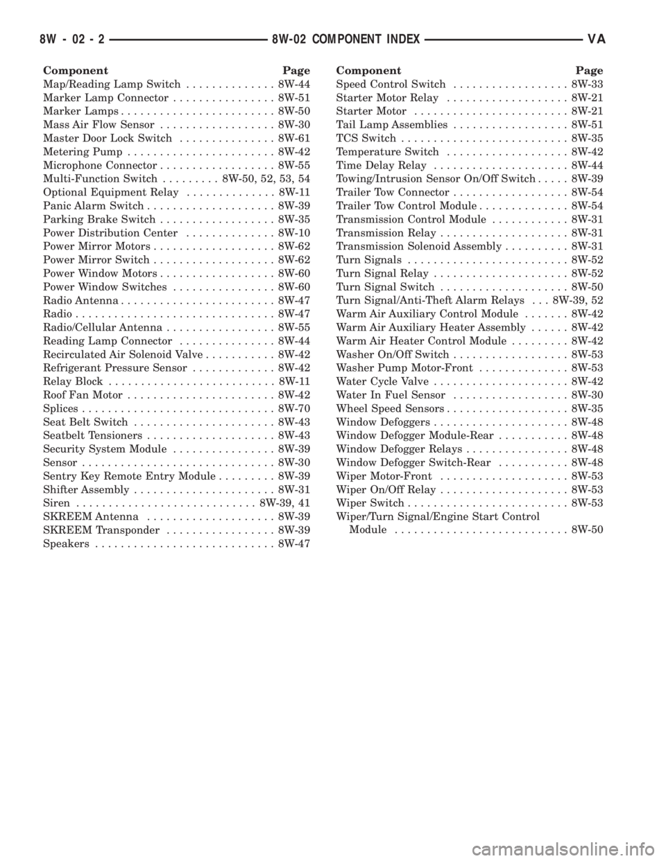
Component Page
Map/Reading Lamp Switch.............. 8W-44
Marker Lamp Connector................ 8W-51
Marker Lamps........................ 8W-50
Mass Air Flow Sensor.................. 8W-30
Master Door Lock Switch............... 8W-61
Metering Pump....................... 8W-42
Microphone Connector.................. 8W-55
Multi-Function Switch......... 8W-50, 52, 53, 54
Optional Equipment Relay.............. 8W-11
Panic Alarm Switch.................... 8W-39
Parking Brake Switch.................. 8W-35
Power Distribution Center.............. 8W-10
Power Mirror Motors................... 8W-62
Power Mirror Switch................... 8W-62
Power Window Motors.................. 8W-60
Power Window Switches................ 8W-60
Radio Antenna........................ 8W-47
Radio............................... 8W-47
Radio/Cellular Antenna................. 8W-55
Reading Lamp Connector............... 8W-44
Recirculated Air Solenoid Valve........... 8W-42
Refrigerant Pressure Sensor............. 8W-42
Relay Block.......................... 8W-11
Roof Fan Motor....................... 8W-42
Splices.............................. 8W-70
Seat Belt Switch...................... 8W-43
Seatbelt Tensioners.................... 8W-43
Security System Module................ 8W-39
Sensor.............................. 8W-30
Sentry Key Remote Entry Module......... 8W-39
Shifter Assembly...................... 8W-31
Siren............................ 8W-39, 41
SKREEM Antenna.................... 8W-39
SKREEM Transponder................. 8W-39
Speakers............................ 8W-47Component Page
Speed Control Switch.................. 8W-33
Starter Motor Relay................... 8W-21
Starter Motor........................ 8W-21
Tail Lamp Assemblies.................. 8W-51
TCS Switch.......................... 8W-35
Temperature Switch................... 8W-42
Time Delay Relay..................... 8W-44
Towing/Intrusion Sensor On/Off Switch..... 8W-39
Trailer Tow Connector.................. 8W-54
Trailer Tow Control Module.............. 8W-54
Transmission Control Module............ 8W-31
Transmission Relay.................... 8W-31
Transmission Solenoid Assembly.......... 8W-31
Turn Signals......................... 8W-52
Turn Signal Relay..................... 8W-52
Turn Signal Switch.................... 8W-50
Turn Signal/Anti-Theft Alarm Relays . . . 8W-39, 52
Warm Air Auxiliary Control Module....... 8W-42
Warm Air Auxiliary Heater Assembly...... 8W-42
Warm Air Heater Control Module......... 8W-42
Washer On/Off Switch.................. 8W-53
Washer Pump Motor-Front.............. 8W-53
Water Cycle Valve..................... 8W-42
Water In Fuel Sensor.................. 8W-30
Wheel Speed Sensors................... 8W-35
Window Defoggers..................... 8W-48
Window Defogger Module-Rear........... 8W-48
Window Defogger Relays................ 8W-48
Window Defogger Switch-Rear........... 8W-48
Wiper Motor-Front.................... 8W-53
Wiper On/Off Relay.................... 8W-53
Wiper Switch......................... 8W-53
Wiper/Turn Signal/Engine Start Control
Module........................... 8W-50
8W - 02 - 2 8W-02 COMPONENT INDEXVA
Page 467 of 1232
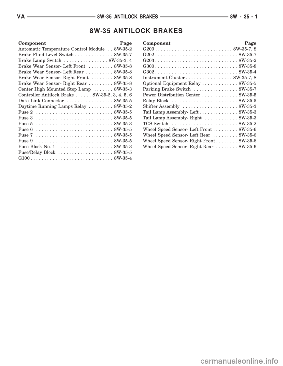
8W-35 ANTILOCK BRAKES
Component Page
Automatic Temperature Control Module . . 8W-35-2
Brake Fluid Level Switch.............. 8W-35-7
Brake Lamp Switch................ 8W-35-3, 4
Brake Wear Sensor- Left Front......... 8W-35-8
Brake Wear Sensor- Left Rear.......... 8W-35-8
Brake Wear Sensor- Right Front........ 8W-35-8
Brake Wear Sensor- Right Rear......... 8W-35-8
Center High Mounted Stop Lamp....... 8W-35-3
Controller Antilock Brake...... 8W-35-2, 3, 4, 5, 6
Data Link Connector................. 8W-35-5
Daytime Running Lamps Relay......... 8W-35-2
Fuse 2............................ 8W-35-5
Fuse 3............................ 8W-35-5
Fuse 5............................ 8W-35-3
Fuse 6............................ 8W-35-5
Fuse 7............................ 8W-35-5
Fuse 9............................ 8W-35-5
Fuse Block No. 1.................... 8W-35-3
Fuse/Relay Block.................... 8W-35-5
G100.............................. 8W-35-4Component Page
G200............................ 8W-35-7, 8
G202.............................. 8W-35-7
G203.............................. 8W-35-2
G300.............................. 8W-35-8
G302.............................. 8W-35-4
Instrument Cluster................. 8W-35-7, 8
Optional Equipment Relay............. 8W-35-5
Parking Brake Switch................ 8W-35-7
Power Distribution Center............. 8W-35-5
Relay Block........................ 8W-35-5
Shifter Assembly.................... 8W-35-3
Tail Lamp Assembly- Left.............. 8W-35-3
Tail Lamp Assembly- Right............ 8W-35-3
TCS Switch........................ 8W-35-2
Wheel Speed Sensor- Left Front......... 8W-35-6
Wheel Speed Sensor- Left Rear......... 8W-35-6
Wheel Speed Sensor- Right Front........ 8W-35-6
Wheel Speed Sensor- Right Rear........ 8W-35-6
VA8W-35 ANTILOCK BRAKES 8W - 35 - 1
Page 629 of 1232
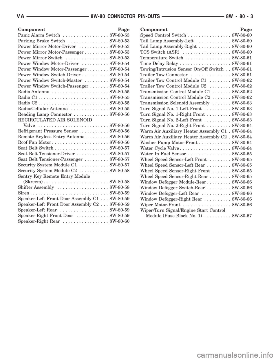
Component Page
Panic Alarm Switch................. 8W-80-53
Parking Brake Switch............... 8W-80-53
Power Mirror Motor-Driver........... 8W-80-53
Power Mirror Motor-Passenger......... 8W-80-53
Power Mirror Switch................ 8W-80-53
Power Window Motor-Driver.......... 8W-80-54
Power Window Motor-Passenger........ 8W-80-54
Power Window Switch-Driver.......... 8W-80-54
Power Window Switch-Master......... 8W-80-54
Power Window Switch-Passenger....... 8W-80-54
Radio Antenna..................... 8W-80-55
Radio C1.......................... 8W-80-55
Radio C2.......................... 8W-80-55
Radio/Cellular Antenna.............. 8W-80-55
Reading Lamp Connector............. 8W-80-56
RECIRCULATED AIR SOLENOID
Valve.......................... 8W-80-56
Refrigerant Pressure Sensor........... 8W-80-56
Remote Keyless Entry Antenna........ 8W-80-56
Roof Fan Motor..................... 8W-80-56
Seat Belt Switch.................... 8W-80-57
Seat Belt Tensioner-Driver............ 8W-80-57
Seat Belt Tensioner-Passenger......... 8W-80-57
Security System Module C1........... 8W-80-57
Security System Module C2........... 8W-80-58
Sentry Key Remote Entry Module
(Skreem)........................ 8W-80-58
Shifter Assembly................... 8W-80-58
Siren............................. 8W-80-59
Speaker-Left Front Door Assembly C1 . . . 8W-80-59
Speaker-Left Front Door Assembly C2 . . . 8W-80-59
Speaker-Left Rear.................. 8W-80-59
Speaker-Right Front Door............ 8W-80-59
Speaker-Right Rear................. 8W-80-60Component Page
Speed Control Switch................ 8W-80-60
Tail Lamp Assembly-Left............. 8W-80-60
Tail Lamp Assembly-Right............ 8W-80-60
TCS Switch (ASR).................. 8W-80-60
Temperature Switch................. 8W-80-61
Time Delay Relay................... 8W-80-61
Towing/Intrusion Sensor On/Off Switch . . 8W-80-61
Trailer Tow Connector............... 8W-80-61
Trailer Tow Control Module C1........ 8W-80-62
Trailer Tow Control Module C2........ 8W-80-62
Transmission Control Module C1....... 8W-80-62
Transmission Control Module C2....... 8W-80-62
Transmission Solenoid Assembly....... 8W-80-63
Turn Signal No. 1-Left Front.......... 8W-80-63
Turn Signal No. 1-Right Front......... 8W-80-63
Turn Signal No. 2-Left Front.......... 8W-80-63
Turn Signal No. 2-Right Front......... 8W-80-64
Warm Air Auxiliary Heater Assembly C1 . 8W-80-64
Warm Air Auxiliary Heater Assembly C2 . 8W-80-64
Washer Pump Motor-Front............ 8W-80-64
Water Cycle Valve................... 8W-80-64
Water In Fuel Sensor................ 8W-80-65
Wheel Speed Sensor-Left Front........ 8W-80-65
Wheel Speed Sensor-Left Rear......... 8W-80-65
Wheel Speed Sensor-Right Front....... 8W-80-65
Wheel Speed Sensor-Right Rear........ 8W-80-65
Window Defogger Module-Rear......... 8W-80-66
Window Defogger Switch-Rear......... 8W-80-66
Window Defogger-Left Rear........... 8W-80-66
Window Defogger-Right Rear.......... 8W-80-66
Wiper Motor-Front.................. 8W-80-66
Wiper/Turn Signal/Engine Start Control
Module (Fuse Block No. 1).......... 8W-80-67
VA8W-80 CONNECTOR PIN-OUTS 8W - 80 - 3
Page 653 of 1232
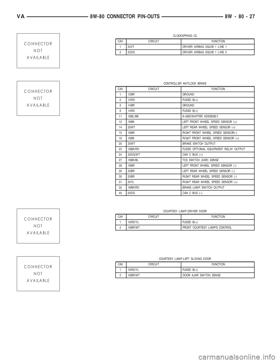
CLOCKSPRING C2
CAV CIRCUIT FUNCTION
1 20VT DRIVER AIRBAG SQUIB 1 LINE 1
2 20DG DRIVER AIRBAG SQUIB 1 LINE 2
CONTROLLER ANTILOCK BRAKE
CAV CIRCUIT FUNCTION
1 12BR GROUND
2 12RD FUSED B(+)
5 14BR GROUND
6 14RD FUSED B(+)
11 18BL/BK K-ABS/SHIFTER ASSEMBLY
12 18BK LEFT FRONT WHEEL SPEED SENSOR (+)
14 20WT LEFT REAR WHEEL SPEED SENSOR (+)
15 18BR RIGHT FRONT WHEEL SPEED SENSOR(-)
16 18BK RIGHT FRONT WHEEL SPEED SENSOR (+)
20 20WT BRAKE SWITCH OUTPUT
23 18BK/RD FUSED OPTIONAL EQUIPMENT RELAY OUTPUT
24 20DG/WT CAN C BUS (+)
27 18BK/BL TCS SWITCH (ASR) SENSE
28 18BR LEFT FRONT WHEEL SPEED SENSOR (-)
29 20BR LEFT REAR WHEEL SPEED SENSOR (-)
30 20BR RIGHT REAR WHEEL SPEED SENSOR (-)
31 20YL RIGHT REAR WHEEL SPEED SENSOR (+)
32 18BK/RD BRAKE LAMP SWITCH OUTPUT
40 20DG CAN C BUS (-)
COURTESY LAMP-DRIVER DOOR
CAV CIRCUIT FUNCTION
1 16RD/YL FUSED B(+)
2 16BR/WT FRONT COURTESY LAMPS CONTROL
COURTESY LAMP-LEFT SLIDING DOOR
CAV CIRCUIT FUNCTION
1 16RD/YL FUSED B(+)
2 16BR/WT DOOR AJAR SWITCH SENSE
VA8W-80 CONNECTOR PIN-OUTS 8W - 80 - 27