2005 MERCEDES-BENZ SPRINTER wheel
[x] Cancel search: wheelPage 865 of 1232
COLUMN
TABLE OF CONTENTS
page page
COLUMN
SPECIFICATIONS - TORQUE CHART.........5
INTERMEDIATE SHAFT
REMOVAL.............................5
INSTALLATION..........................5
KEY/LOCK CYLINDER
REMOVAL.............................6INSTALLATION..........................7
STEERING WHEEL
REMOVAL.............................7
INSTALLATION..........................7
COLUMN
SPECIFICATIONS - TORQUE CHART
TORQUE SPECIFICATIONS
DESCRIPTION N´m Ft. Lbs. In. Lbs.
Steering Wheel With
Airbag To Steering Shaft80 59 Ð
Jacket Tube For Steering
Shaft To Waist Rail25 18 221
U-Joint To Steering Gear
Shaft24 18 212
INTERMEDIATE SHAFT
REMOVAL
(1) Disconnect the ground cable from the battery.
(2) Remove the air bag module from the steering
wheel.
(3) Turn the steering wheel and lock the steering
wheel in the straight ahead position.The position
of the steering gear must not be altered again
for the entire duration of the work procedure.
(4) Remove the electrical center.
(5) Remove the steering wheel bolt.
(6) Remove the steering wheel from the steering
column.
(7) Remove the clockspring.Unscrew the retain-
ing bolts just enough to be able to remove the
clockspring. Do not twist or disassemble the
clockspring.
(8) Remove the combination switch.
(9) Disconnect the electrical connector for the igni-
tion lock.(10) Remove the spring for the brake pedal from
the steering column.
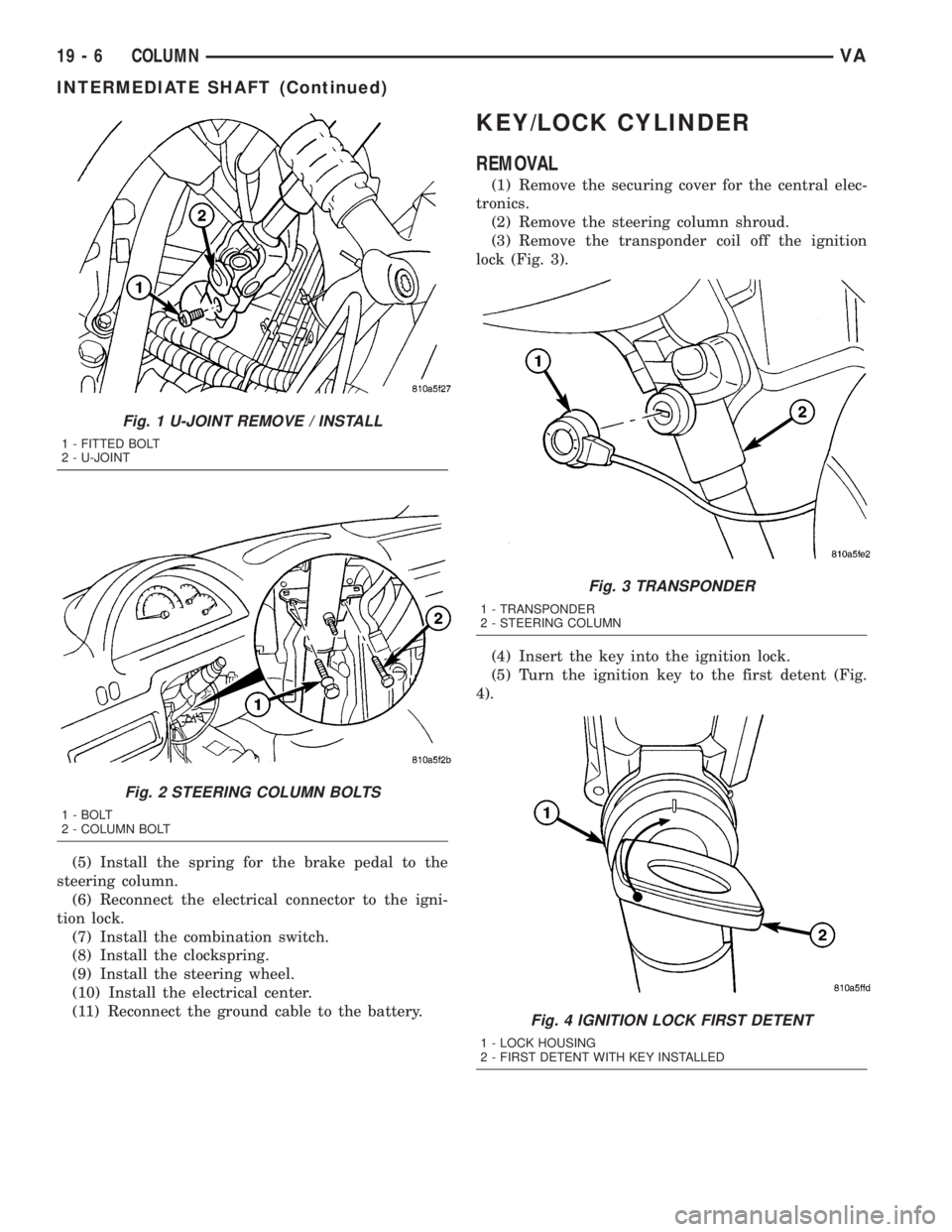
(11) Remove the fitted bolt from the universal joint
(Fig. 1).
(12) Remove the bolts in the steering column
bracket (Fig. 2).
(13) Remove the steering shaft with the universal
joint off the steering gear drive shaft (Fig. 1).
(14) Pull the steering shaft out of the rubber grom-
met in the cab floor.
INSTALLATION
(1) Install the steering shaft through the rubber
grommet in the cab floor.Ensure that the rubber
grommet is properly seated.
(2) Install the steering shaft with the universal
joint onto the steering gear shaft (Fig. 1).
(3) Install the bolts in the steering column bracket
(Fig. 2). Tighten to 24 N´m (18 ft. lbs.).
(4) Install the universal joint on the steering gear
shaft (Fig. 1). Tighten to 24 N´m (18 ft. lbs.).
VACOLUMN 19 - 5
Page 866 of 1232
(5) Install the spring for the brake pedal to the
steering column.
(6) Reconnect the electrical connector to the igni-
tion lock.
(7) Install the combination switch.
(8) Install the clockspring.
(9) Install the steering wheel.
(10) Install the electrical center.
(11) Reconnect the ground cable to the battery.
KEY/LOCK CYLINDER
REMOVAL
(1) Remove the securing cover for the central elec-
tronics.
(2) Remove the steering column shroud.
(3) Remove the transponder coil off the ignition
lock (Fig. 3).
(4) Insert the key into the ignition lock.
(5) Turn the ignition key to the first detent (Fig.
4).
Fig. 1 U-JOINT REMOVE / INSTALL
1 - FITTED BOLT
2 - U-JOINT
Fig. 2 STEERING COLUMN BOLTS
1 - BOLT
2 - COLUMN BOLT
Fig. 3 TRANSPONDER
1 - TRANSPONDER
2 - STEERING COLUMN
Fig. 4 IGNITION LOCK FIRST DETENT
1 - LOCK HOUSING
2 - FIRST DETENT WITH KEY INSTALLED
19 - 6 COLUMNVA
INTERMEDIATE SHAFT (Continued)
Page 867 of 1232
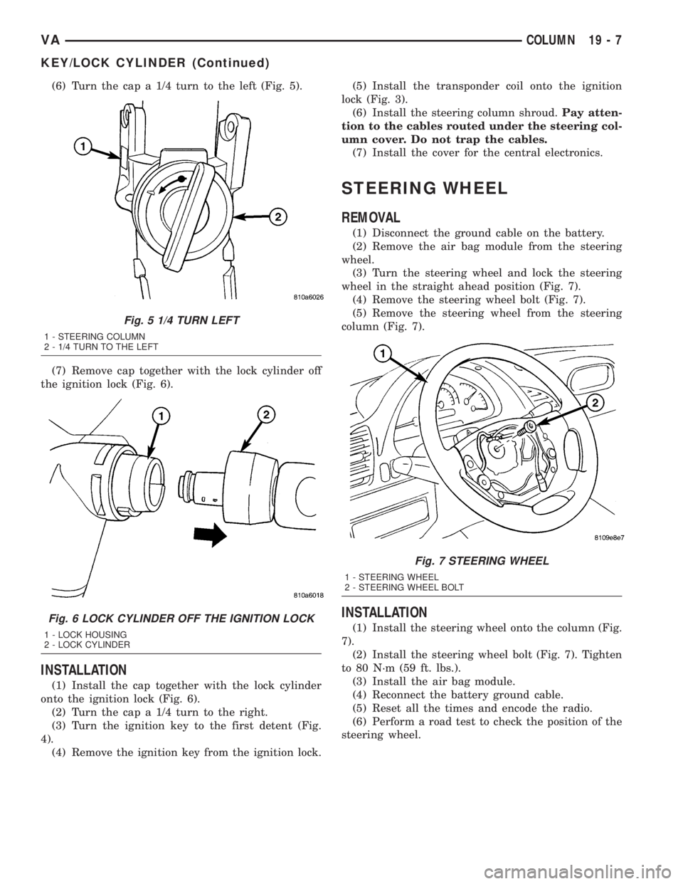
(6) Turn the cap a 1/4 turn to the left (Fig. 5).
(7) Remove cap together with the lock cylinder off
the ignition lock (Fig. 6).
INSTALLATION
(1) Install the cap together with the lock cylinder
onto the ignition lock (Fig. 6).
(2) Turn the cap a 1/4 turn to the right.
(3) Turn the ignition key to the first detent (Fig.
4).
(4) Remove the ignition key from the ignition lock.(5) Install the transponder coil onto the ignition
lock (Fig. 3).
(6) Install the steering column shroud.Pay atten-
tion to the cables routed under the steering col-
umn cover. Do not trap the cables.
(7) Install the cover for the central electronics.
STEERING WHEEL
REMOVAL
(1) Disconnect the ground cable on the battery.
(2) Remove the air bag module from the steering
wheel.
(3) Turn the steering wheel and lock the steering
wheel in the straight ahead position (Fig. 7).
(4) Remove the steering wheel bolt (Fig. 7).
(5) Remove the steering wheel from the steering
column (Fig. 7).
INSTALLATION
(1) Install the steering wheel onto the column (Fig.
7).
(2) Install the steering wheel bolt (Fig. 7). Tighten
to 80 N´m (59 ft. lbs.).
(3) Install the air bag module.
(4) Reconnect the battery ground cable.
(5) Reset all the times and encode the radio.
(6) Perform a road test to check the position of the
steering wheel.
Fig. 5 1/4 TURN LEFT
1 - STEERING COLUMN
2 - 1/4 TURN TO THE LEFT
Fig. 6 LOCK CYLINDER OFF THE IGNITION LOCK
1 - LOCK HOUSING
2 - LOCK CYLINDER
Fig. 7 STEERING WHEEL
1 - STEERING WHEEL
2 - STEERING WHEEL BOLT
VACOLUMN 19 - 7
KEY/LOCK CYLINDER (Continued)
Page 868 of 1232
GEAR
TABLE OF CONTENTS
page page
GEAR
DESCRIPTION..........................8
REMOVAL.............................8INSTALLATION..........................8
SPECIFICATIONS - TORQUE CHART.........9
GEAR
DESCRIPTION
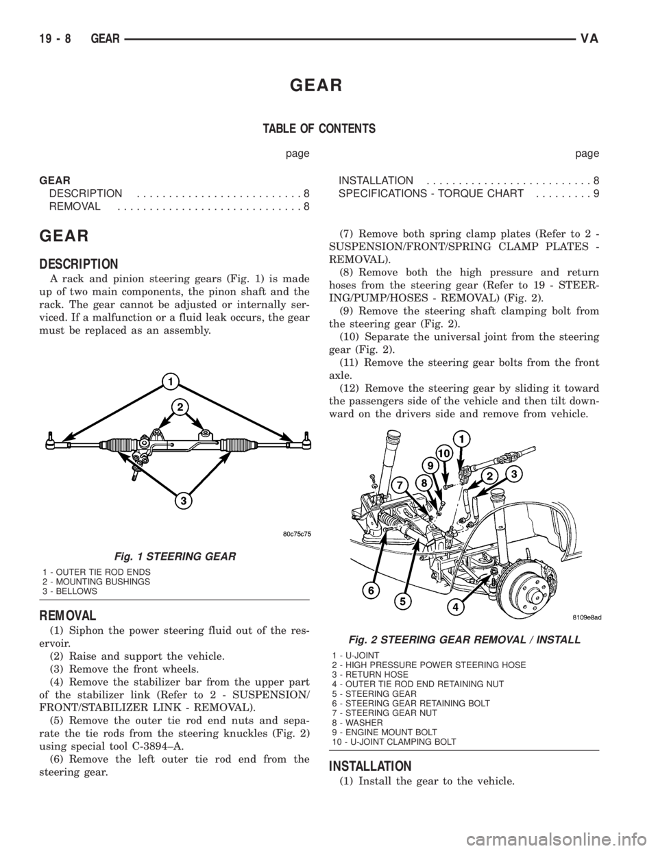
A rack and pinion steering gears (Fig. 1) is made
up of two main components, the pinon shaft and the
rack. The gear cannot be adjusted or internally ser-
viced. If a malfunction or a fluid leak occurs, the gear
must be replaced as an assembly.
REMOVAL
(1) Siphon the power steering fluid out of the res-
ervoir.
(2) Raise and support the vehicle.
(3) Remove the front wheels.
(4) Remove the stabilizer bar from the upper part
of the stabilizer link (Refer to 2 - SUSPENSION/
FRONT/STABILIZER LINK - REMOVAL).
(5) Remove the outer tie rod end nuts and sepa-
rate the tie rods from the steering knuckles (Fig. 2)
using special tool C-3894±A.
(6) Remove the left outer tie rod end from the
steering gear.(7) Remove both spring clamp plates (Refer to 2 -
SUSPENSION/FRONT/SPRING CLAMP PLATES -
REMOVAL).
(8) Remove both the high pressure and return
hoses from the steering gear (Refer to 19 - STEER-
ING/PUMP/HOSES - REMOVAL) (Fig. 2).
(9) Remove the steering shaft clamping bolt from
the steering gear (Fig. 2).
(10) Separate the universal joint from the steering
gear (Fig. 2).
(11) Remove the steering gear bolts from the front
axle.
(12) Remove the steering gear by sliding it toward
the passengers side of the vehicle and then tilt down-
ward on the drivers side and remove from vehicle.
INSTALLATION
(1) Install the gear to the vehicle.
Fig. 1 STEERING GEAR
1 - OUTER TIE ROD ENDS
2 - MOUNTING BUSHINGS
3 - BELLOWS
Fig. 2 STEERING GEAR REMOVAL / INSTALL
1 - U-JOINT
2 - HIGH PRESSURE POWER STEERING HOSE
3 - RETURN HOSE
4 - OUTER TIE ROD END RETAINING NUT
5 - STEERING GEAR
6 - STEERING GEAR RETAINING BOLT
7 - STEERING GEAR NUT
8 - WASHER
9 - ENGINE MOUNT BOLT
10 - U-JOINT CLAMPING BOLT
19 - 8 GEARVA
Page 869 of 1232
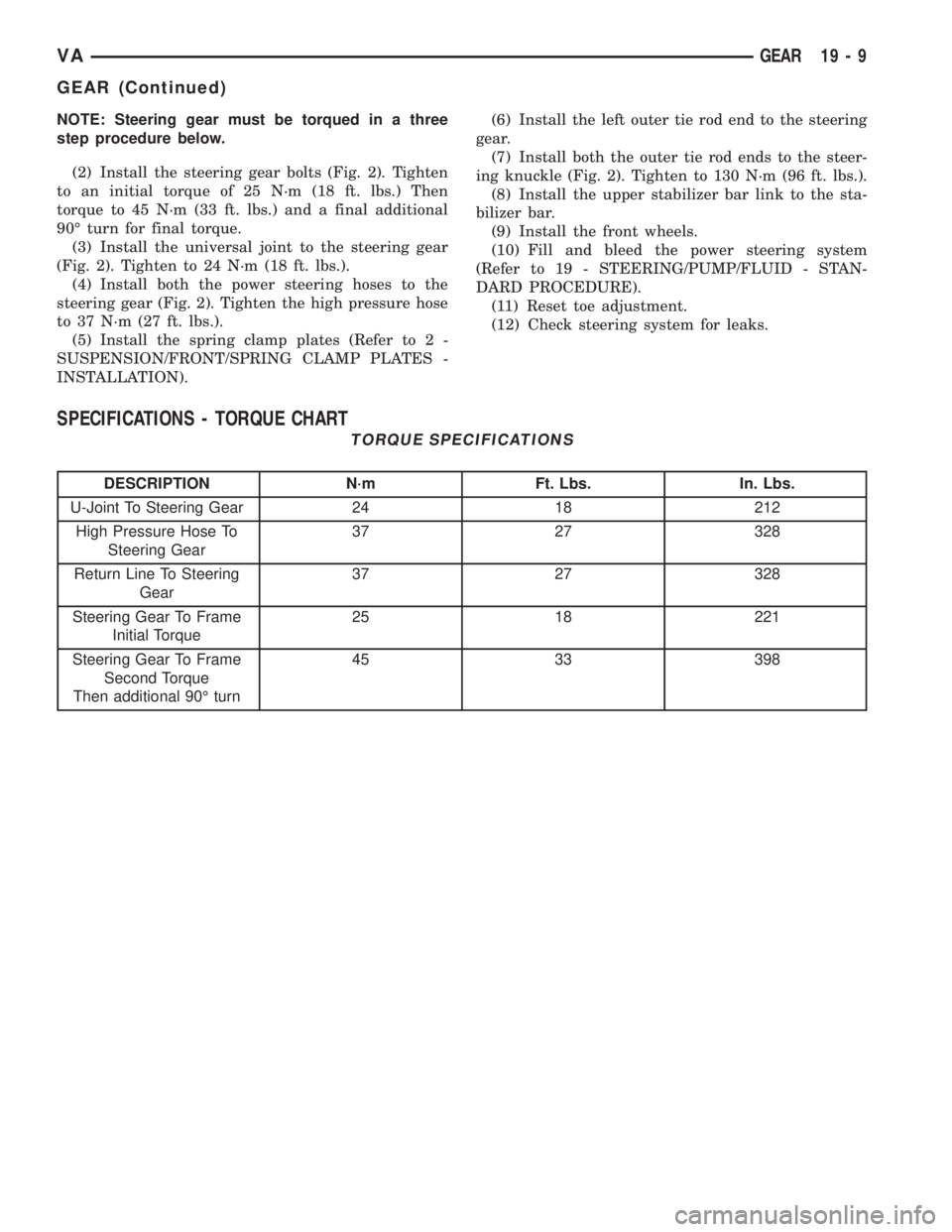
NOTE: Steering gear must be torqued in a three
step procedure below.
(2) Install the steering gear bolts (Fig. 2). Tighten
to an initial torque of 25 N´m (18 ft. lbs.) Then
torque to 45 N´m (33 ft. lbs.) and a final additional
90É turn for final torque.
(3) Install the universal joint to the steering gear
(Fig. 2). Tighten to 24 N´m (18 ft. lbs.).
(4) Install both the power steering hoses to the
steering gear (Fig. 2). Tighten the high pressure hose
to 37 N´m (27 ft. lbs.).
(5) Install the spring clamp plates (Refer to 2 -
SUSPENSION/FRONT/SPRING CLAMP PLATES -
INSTALLATION).(6) Install the left outer tie rod end to the steering
gear.
(7) Install both the outer tie rod ends to the steer-
ing knuckle (Fig. 2). Tighten to 130 N´m (96 ft. lbs.).
(8) Install the upper stabilizer bar link to the sta-
bilizer bar.
(9) Install the front wheels.
(10) Fill and bleed the power steering system
(Refer to 19 - STEERING/PUMP/FLUID - STAN-
DARD PROCEDURE).
(11) Reset toe adjustment.
(12) Check steering system for leaks.
SPECIFICATIONS - TORQUE CHART
TORQUE SPECIFICATIONS
DESCRIPTION N´m Ft. Lbs. In. Lbs.
U-Joint To Steering Gear 24 18 212
High Pressure Hose To
Steering Gear37 27 328
Return Line To Steering
Gear37 27 328
Steering Gear To Frame
Initial Torque25 18 221
Steering Gear To Frame
Second Torque
Then additional 90É turn45 33 398
VAGEAR 19 - 9
GEAR (Continued)
Page 870 of 1232
LINKAGE
TABLE OF CONTENTS
page page
LINKAGE
DIAGNOSIS AND TESTING - OUTER TIE ROD
END ................................10
SPECIFICATIONS - TORQUE CHART........10
SPECIAL TOOLS
FRONT SUSPENSION..................11TIE ROD END
REMOVAL.............................11
INSTALLATION.........................11
LINKAGE
DIAGNOSIS AND TESTING - OUTER TIE ROD
END
NOTE: If the outer tie rod end is equipped with a
lubrication fitting, grease the joint then road test
the vehicle before performing test.
(1) Raise the front of the vehicle. Place safety floor
stands under both lower control arms as far outboard
as possible. Lower the vehicle to allow the stands to
support some or all of the vehicle weight.
(2) Remove the front tires.
(3) Mount a dial indicator solidly to the vehicle
steering knuckle and then zero the dial indicator.(4) Position indicator plunger on the topside of the
outer tie rod end.
NOTE: The dial indicator plunger must be perpen-
dicular to the machined surface of the outer tie rod
end.
(5) Position a pry bar in order to pry downwards
on the outer tie rod end.
(6) If the travel exceeds 0.5 mm (0.020 in.), replace
the outer tie rod end (Refer to 19 - STEERING/
LINKAGE/TIE ROD END - REMOVAL).
(7) If the outer tie rod end is within specs reinstall
the front tires (Refer to 22 - TIRES/WHEELS/
WHEELS - STANDARD PROCEDURE).
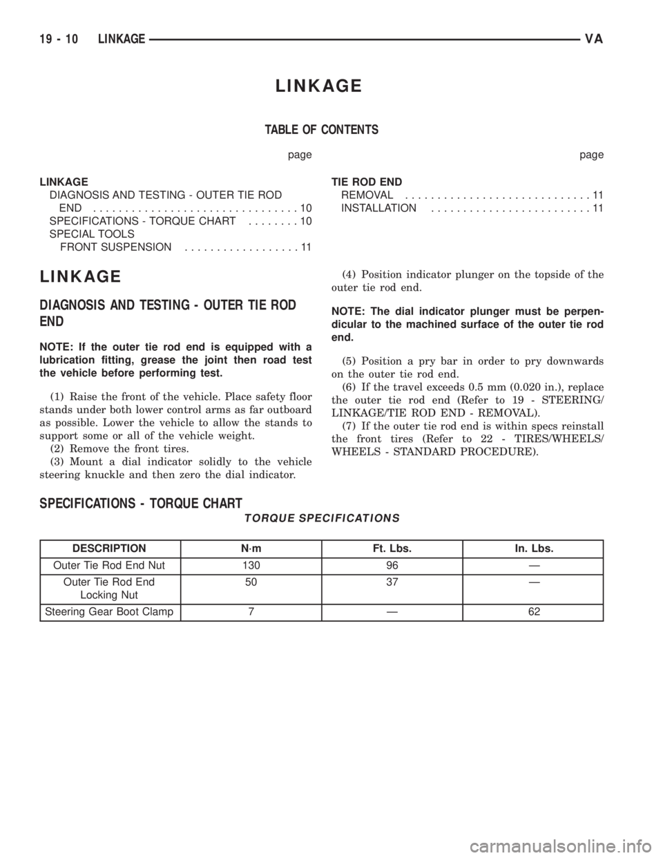
SPECIFICATIONS - TORQUE CHART
TORQUE SPECIFICATIONS
DESCRIPTION N´m Ft. Lbs. In. Lbs.
Outer Tie Rod End Nut 130 96 Ð
Outer Tie Rod End
Locking Nut50 37 Ð
Steering Gear Boot Clamp 7 Ð 62
19 - 10 LINKAGEVA
Page 871 of 1232
SPECIAL TOOLS
FRONT SUSPENSION
TIE ROD END
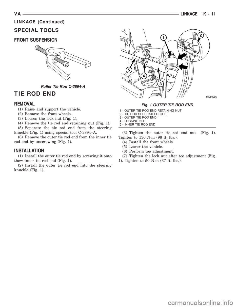
REMOVAL
(1) Raise and support the vehicle.
(2) Remove the front wheels.
(3) Loosen the lock nut (Fig. 1).
(4) Remove the tie rod end retaining nut (Fig. 1).
(5) Separate the tie rod end from the steering
knuckle (Fig. 1) using special tool C-3894±A.
(6) Remove the outer tie rod end from the inner tie
rod end by unscrewing (Fig. 1).
INSTALLATION
(1) Install the outer tie rod end by screwing it onto
thew inner tie rod end (Fig. 1).
(2) Install the outer tie rod end into the steering
knuckle (Fig. 1).(3) Tighten the outer tie rod end nut (Fig. 1).
Tighten to 130 N´m (96 ft. lbs.).
(4) Install the front wheels.
(5) Lower the vehicle.
(6) Perform toe adjustment.
(7) Tighten the lock nut after toe adjustment (Fig.
1). Tighten to 50 N´m (37 ft. lbs.).
Puller Tie Rod C-3894-A
Fig. 1 OUTER TIE ROD END
1 - OUTER TIE ROD END RETAINING NUT
2 - TIE ROD SEPERATOR TOOL
3 - OUTER TIE ROD END
4 - LOCKING NUT
5 - INNER TIE ROD END
VALINKAGE 19 - 11
LINKAGE (Continued)
Page 873 of 1232
Wipe filler cap clean, then check the fluid level.
The dipstick should indicateCOLDwhen the fluid is
at normal temperature.
(1) Turn steering wheel all the way to the left
(2) Fill the pump fluid reservoir to the proper level
and let the fluid settle for at least two (2) minutes.
(3) Raise the front wheels off the ground.
(4)
Slowly turn the steering wheel lock-to-lock 20
times with the engine off while checking the fluid level.
NOTE: For vehicles with long return lines or oil
coolers turn wheel 40 times.
(5) Start the engine. With the engine idling main-
tain the fluid level.
(6) Lower the front wheels and let the engine idle
for two minutes.
(7) Turn the steering wheel in both direction and
verify power assist and quiet operation of the pump.
If the fluid is extremely foamy or milky looking,
allow the vehicle to stand a few minutes and repeat
the procedure.
CAUTION: Do not run a vehicle with foamy fluid for
an extended period. This may cause pump damage.
STANDARD PROCEDURE - FLUSHING POWER
STEERING SYSTEM
Flushing is required when the power steering/hy-
draulic booster system fluid has become contami-
nated. Contaminated fluid in the steering/booster
system can cause seal deterioration and affect steer-
ing gear/booster spool valve operation.
(1) Raise the front end of the vehicle off the
ground until the wheels are free to turn.
(2) Remove the return line from the pump.
NOTE: If vehicle is equipped with a hydraulic
booster remove both return lines from the pump.
(3) Plug the return line port/ports at the pump.
(4) Position the return line/lines into a large con-
tainer to catch the fluid.
(5) While an assistant is filling the pump reservoir
start the engine.
(6) With the engine running at idle turn the wheel
back and forth.
NOTE: Do not contact or hold the wheel against the
steering stops.
(7) Run a quart of fluid through the system then
stop the engine and install the return line/lines.
(8) Fill the system with fluid and perform Steering
Pump Initial Operation, (Refer to 19 - STEERING/
PUMP - STANDARD PROCEDURE).(9) Start the engine and run it for fifteen minutes
then stop the engine.
(10) Remove the return line/lines from the pump
and plug the pump port/ports.
(11) Pour fresh fluid into the reservoir and check
the draining fluid for contamination. If the fluid is
still contaminated, then flush the system again.
(12) Install the return line/lines and perform
Steering Pump Initial Operation, (Refer to 19 -
STEERING/PUMP - STANDARD PROCEDURE).
REMOVAL
(1) Remove the belt from the power steering pump.
(2) Siphon as much power steering fluid as possi-
ble out of the reservoir.
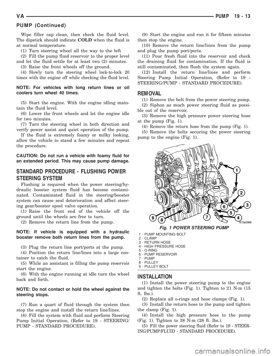
(3) Remove the high pressure power steering hose
at the pump (Fig. 1).
(4)
Remove the return hose from the pump (Fig. 1).
(5) Remove the bolts securing the power steering
pump to the engine (Fig. 1).
INSTALLATION
(1) Install the power steering pump to the engine
and tighten the bolts (Fig. 1). Tighten to 21 N´m (15
ft. lbs.).
(2) Replace all o-rings and hose clamps (Fig. 1).
(3) Install the return hose to the pump and tighten
the clamp (Fig. 1).
(4) Install the high pressure hose to the pump
(Fig. 1). Tighten to 38 N´m (28 ft. lbs.).
(5)
Fill the power steering fluid (Refer to 19 - STEER-
ING/PUMP/FLUID - STANDARD PROCEDURE).
Fig. 1 POWER STEERING PUMP
1 - PUMP MOUNTING BOLT
2 - CLAMP
3 - RETURN HOSE
4 - HIGH PRESSURE HOSE
5 - O-RING
6 - PUMP RESERVOIR
7 - PUMP
8 - PULLEY
9 - PULLEY BOLT
VAPUMP 19 - 13
PUMP (Continued)