Page 982 of 1232
DISASSEMBLY
(1) Remove retaining ring (5) (Fig. 143) from hol-
low shaft (1).
(2) Remove rear sun gear (4) with the K3 inter-
nally toothed disk carrier and rear freewheeling
clutch F2 (3).(3) Remove snap-ring (2) (Fig. 143) for freewheel.
(4) Press freewheeling clutch out of sun gear.
(5) Check O-rings (6), replace if necessary.
(6) Check the anti-friction bearing (Fig. 144) in the
rear planetary sun gear for damage. Replace as nec-
essary.
Fig. 143 Freewheeling Clutch F2
1 - HOLLOW SHAFT 4 - K3 INNER DISC CARRIER AND REAR PLANETARY SUN GEAR
2 - SNAP-RING 5 - RETAINING RING
3 - FREEWHEELING CLUTCH F2 6 - O-RINGS
21 - 106 AUTOMATIC TRANSMISSION - NAG1VA
FREEWHEELING CLUTCH (Continued)
Page 983 of 1232
ASSEMBLY
(1) Press freewheeling clutch F2 (3) (Fig. 145) into
sun gear (4).
(2) Install snap-ring (2) for freewheeling clutch.
(3) Check O-rings (6) (Fig. 145) on hollow shaft,
replace if necessary.
(4) Install rear sun gear (4) with K3 internally
toothed disc carrier and rear freewheeling clutch (3)
onto the hollow shaft.
(5) Install retaining ring (5) onto hollow shaft (1).
Fig. 144 Freewheeling Clutch F2 Anti-Friction
Bearing
1 - K3 INNER DISC CARRIER AND REAR PLANETARY SUN
GEAR
2 - ANTI-FRICTION BEARING
3 - FREEWHEELING CLUTCH F2
VAAUTOMATIC TRANSMISSION - NAG1 21 - 107
FREEWHEELING CLUTCH (Continued)
Page 984 of 1232
Fig. 145 Freewheeling Clutch F2
1 - HOLLOW SHAFT 4 - K3 INNER DISC CARRIER AND REAR PLANETARY SUN GEAR
2 - SNAP-RING 5 - RETAINING RING
3 - FREEWHEELING CLUTCH F2 6 - O-RINGS
21 - 108 AUTOMATIC TRANSMISSION - NAG1VA
FREEWHEELING CLUTCH (Continued)
Page 995 of 1232

INPUT SPEED SENSORS
DESCRIPTION
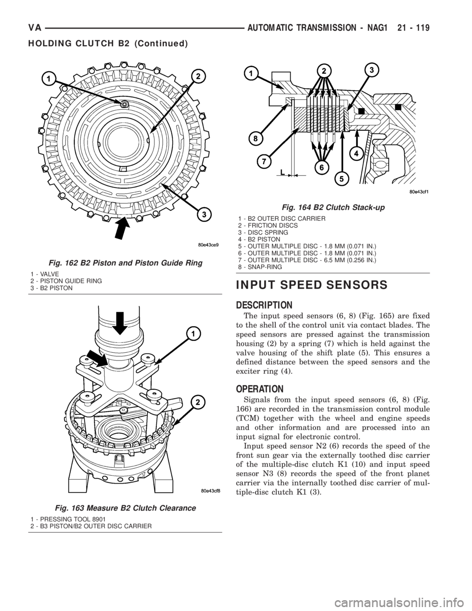
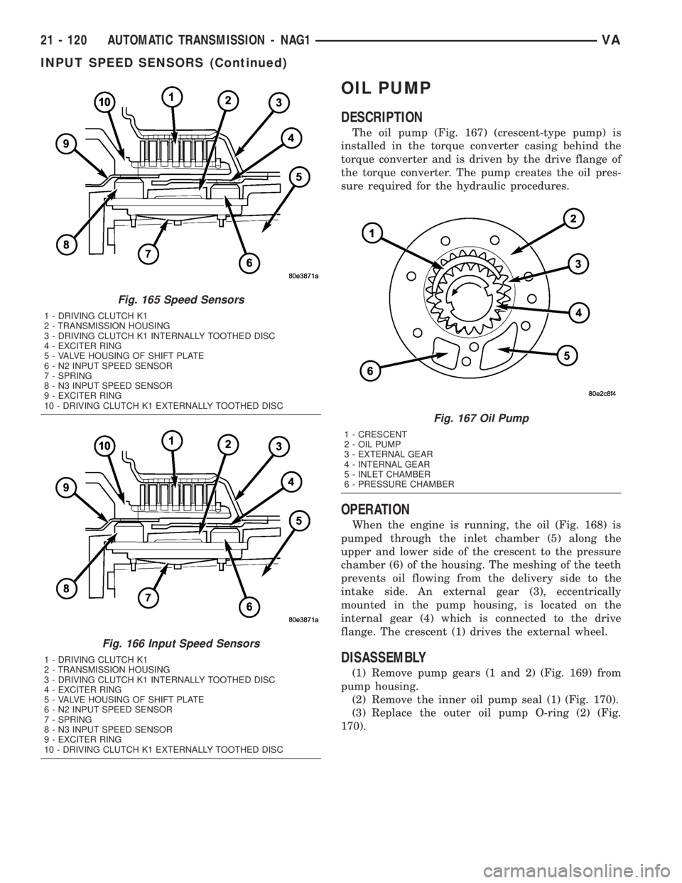
The input speed sensors (6, 8) (Fig. 165) are fixed
to the shell of the control unit via contact blades. The
speed sensors are pressed against the transmission
housing (2) by a spring (7) which is held against the
valve housing of the shift plate (5). This ensures a
defined distance between the speed sensors and the
exciter ring (4).
OPERATION
Signals from the input speed sensors (6, 8) (Fig.
166) are recorded in the transmission control module
(TCM) together with the wheel and engine speeds
and other information and are processed into an
input signal for electronic control.
Input speed sensor N2 (6) records the speed of the
front sun gear via the externally toothed disc carrier
of the multiple-disc clutch K1 (10) and input speed
sensor N3 (8) records the speed of the front planet
carrier via the internally toothed disc carrier of mul-
tiple-disc clutch K1 (3).
Fig. 162 B2 Piston and Piston Guide Ring
1 - VALVE
2 - PISTON GUIDE RING
3 - B2 PISTON
Fig. 163 Measure B2 Clutch Clearance
1 - PRESSING TOOL 8901
2 - B3 PISTON/B2 OUTER DISC CARRIER
Fig. 164 B2 Clutch Stack-up
1 - B2 OUTER DISC CARRIER
2 - FRICTION DISCS
3 - DISC SPRING
4 - B2 PISTON
5 - OUTER MULTIPLE DISC - 1.8 MM (0.071 IN.)
6 - OUTER MULTIPLE DISC - 1.8 MM (0.071 IN.)
7 - OUTER MULTIPLE DISC - 6.5 MM (0.256 IN.)
8 - SNAP-RING
VAAUTOMATIC TRANSMISSION - NAG1 21 - 119
HOLDING CLUTCH B2 (Continued)
Page 996 of 1232

OIL PUMP
DESCRIPTION
The oil pump (Fig. 167) (crescent-type pump) is
installed in the torque converter casing behind the
torque converter and is driven by the drive flange of
the torque converter. The pump creates the oil pres-
sure required for the hydraulic procedures.
OPERATION
When the engine is running, the oil (Fig. 168) is
pumped through the inlet chamber (5) along the
upper and lower side of the crescent to the pressure
chamber (6) of the housing. The meshing of the teeth
prevents oil flowing from the delivery side to the
intake side. An external gear (3), eccentrically
mounted in the pump housing, is located on the
internal gear (4) which is connected to the drive
flange. The crescent (1) drives the external wheel.
DISASSEMBLY
(1) Remove pump gears (1 and 2) (Fig. 169) from
pump housing.
(2) Remove the inner oil pump seal (1) (Fig. 170).
(3) Replace the outer oil pump O-ring (2) (Fig.
170).
Fig. 165 Speed Sensors
1 - DRIVING CLUTCH K1
2 - TRANSMISSION HOUSING
3 - DRIVING CLUTCH K1 INTERNALLY TOOTHED DISC
4 - EXCITER RING
5 - VALVE HOUSING OF SHIFT PLATE
6 - N2 INPUT SPEED SENSOR
7 - SPRING
8 - N3 INPUT SPEED SENSOR
9 - EXCITER RING
10 - DRIVING CLUTCH K1 EXTERNALLY TOOTHED DISC
Fig. 166 Input Speed Sensors
1 - DRIVING CLUTCH K1
2 - TRANSMISSION HOUSING
3 - DRIVING CLUTCH K1 INTERNALLY TOOTHED DISC
4 - EXCITER RING
5 - VALVE HOUSING OF SHIFT PLATE
6 - N2 INPUT SPEED SENSOR
7 - SPRING
8 - N3 INPUT SPEED SENSOR
9 - EXCITER RING
10 - DRIVING CLUTCH K1 EXTERNALLY TOOTHED DISC
Fig. 167 Oil Pump
1 - CRESCENT
2 - OIL PUMP
3 - EXTERNAL GEAR
4 - INTERNAL GEAR
5 - INLET CHAMBER
6 - PRESSURE CHAMBER
21 - 120 AUTOMATIC TRANSMISSION - NAG1VA
INPUT SPEED SENSORS (Continued)
Page 1006 of 1232

PLANETARY GEARTRAIN
DESCRIPTION
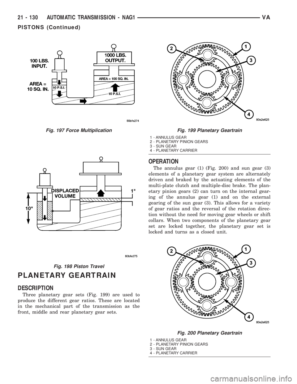
Three planetary gear sets (Fig. 199) are used to
produce the different gear ratios. These are located
in the mechanical part of the transmission as the
front, middle and rear planetary gear sets.
OPERATION
The annulus gear (1) (Fig. 200) and sun gear (3)
elements of a planetary gear system are alternately
driven and braked by the actuating elements of the
multi-plate clutch and multiple-disc brake. The plan-
etary pinion gears (2) can turn on the internal gear-
ing of the annulus gear (1) and on the external
gearing of the sun gear (3). This allows for a variety
of gear ratios and the reversal of the rotation direc-
tion without the need for moving gear wheels or shift
collars. When two components of the planetary gear
set are locked together, the planetary gear set is
locked and turns as a closed unit.
Fig. 197 Force Multiplication
Fig. 198 Piston Travel
Fig. 199 Planetary Geartrain
1 - ANNULUS GEAR
2 - PLANETARY PINION GEARS
3 - SUN GEAR
4 - PLANETARY CARRIER
Fig. 200 Planetary Geartrain
1 - ANNULUS GEAR
2 - PLANETARY PINION GEARS
3 - SUN GEAR
4 - PLANETARY CARRIER
21 - 130 AUTOMATIC TRANSMISSION - NAG1VA
PISTONS (Continued)
Page 1007 of 1232

The torque and engine speed are converted accord-
ing to the lever ratios and the ratio of the number of
teeth on the driven gears to that on the drive gears,
and is referred to as the gear ratio. The overall ratio
of a number of planetary gear sets connected in
series is obtained by multiplying the partial ratios.
DISASSEMBLY
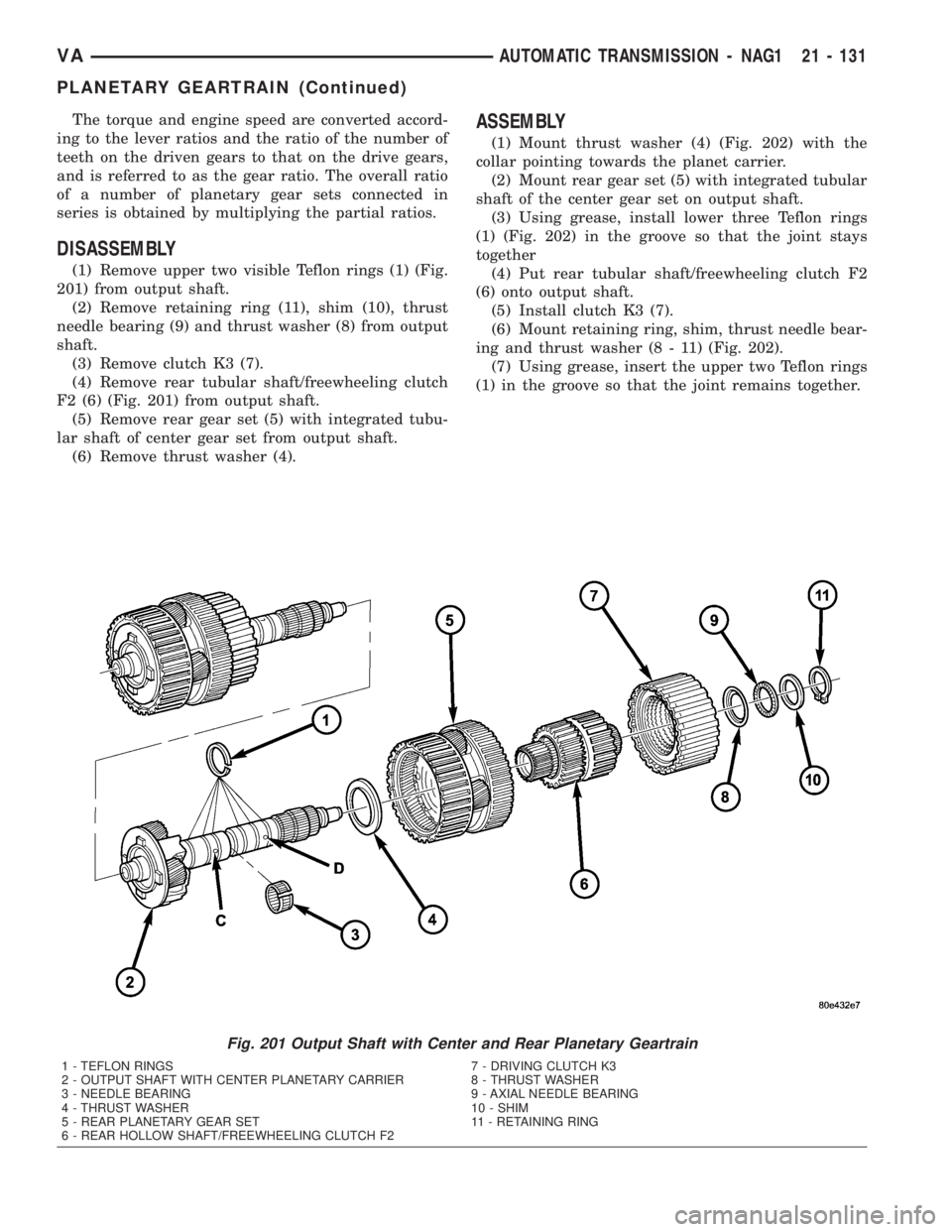
(1) Remove upper two visible Teflon rings (1) (Fig.
201) from output shaft.
(2) Remove retaining ring (11), shim (10), thrust
needle bearing (9) and thrust washer (8) from output
shaft.
(3) Remove clutch K3 (7).
(4) Remove rear tubular shaft/freewheeling clutch
F2 (6) (Fig. 201) from output shaft.
(5) Remove rear gear set (5) with integrated tubu-
lar shaft of center gear set from output shaft.
(6) Remove thrust washer (4).
ASSEMBLY
(1) Mount thrust washer (4) (Fig. 202) with the
collar pointing towards the planet carrier.
(2) Mount rear gear set (5) with integrated tubular
shaft of the center gear set on output shaft.
(3) Using grease, install lower three Teflon rings
(1) (Fig. 202) in the groove so that the joint stays
together
(4) Put rear tubular shaft/freewheeling clutch F2
(6) onto output shaft.
(5) Install clutch K3 (7).
(6) Mount retaining ring, shim, thrust needle bear-
ing and thrust washer (8 - 11) (Fig. 202).
(7) Using grease, insert the upper two Teflon rings
(1) in the groove so that the joint remains together.
Fig. 201 Output Shaft with Center and Rear Planetary Geartrain
1 - TEFLON RINGS 7 - DRIVING CLUTCH K3
2 - OUTPUT SHAFT WITH CENTER PLANETARY CARRIER 8 - THRUST WASHER
3 - NEEDLE BEARING 9 - AXIAL NEEDLE BEARING
4 - THRUST WASHER 10 - SHIM
5 - REAR PLANETARY GEAR SET 11 - RETAINING RING
6 - REAR HOLLOW SHAFT/FREEWHEELING CLUTCH F2
VAAUTOMATIC TRANSMISSION - NAG1 21 - 131
PLANETARY GEARTRAIN (Continued)
Page 1008 of 1232
Fig. 202 Output Shaft with Center and Rear Planetary Geartrain
1 - TEFLON RINGS 7 - DRIVING CLUTCH K3
2 - OUTPUT SHAFT WITH CENTER PLANETARY CARRIER 8 - THRUST WASHER
3 - NEEDLE BEARING 9 - AXIAL NEEDLE BEARING
4 - THRUST WASHER 10 - SHIM
5 - REAR PLANETARY GEAR SET 11 - RETAINING RING
6 - REAR HOLLOW SHAFT/FREEWHEELING CLUTCH F2
21 - 132 AUTOMATIC TRANSMISSION - NAG1VA
PLANETARY GEARTRAIN (Continued)