2005 MERCEDES-BENZ SPRINTER light
[x] Cancel search: lightPage 1115 of 1232
SEAT - FRONT
REMOVAL
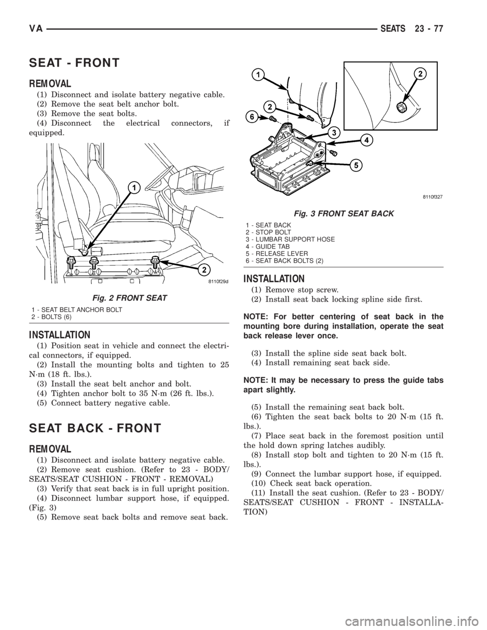
(1) Disconnect and isolate battery negative cable.
(2) Remove the seat belt anchor bolt.
(3) Remove the seat bolts.
(4) Disconnect the electrical connectors, if
equipped.
INSTALLATION
(1) Position seat in vehicle and connect the electri-
cal connectors, if equipped.
(2) Install the mounting bolts and tighten to 25
N´m (18 ft. lbs.).
(3) Install the seat belt anchor and bolt.
(4) Tighten anchor bolt to 35 N´m (26 ft. lbs.).
(5) Connect battery negative cable.
SEAT BACK - FRONT
REMOVAL
(1) Disconnect and isolate battery negative cable.
(2) Remove seat cushion. (Refer to 23 - BODY/
SEATS/SEAT CUSHION - FRONT - REMOVAL)
(3) Verify that seat back is in full upright position.
(4) Disconnect lumbar support hose, if equipped.
(Fig. 3)
(5) Remove seat back bolts and remove seat back.
INSTALLATION
(1) Remove stop screw.
(2) Install seat back locking spline side first.
NOTE: For better centering of seat back in the
mounting bore during installation, operate the seat
back release lever once.
(3) Install the spline side seat back bolt.
(4) Install remaining seat back side.
NOTE: It may be necessary to press the guide tabs
apart slightly.
(5) Install the remaining seat back bolt.
(6) Tighten the seat back bolts to 20 N´m (15 ft.
lbs.).
(7) Place seat back in the foremost position until
the hold down spring latches audibly.
(8) Install stop bolt and tighten to 20 N´m (15 ft.
lbs.).
(9) Connect the lumbar support hose, if equipped.
(10) Check seat back operation.
(11) Install the seat cushion. (Refer to 23 - BODY/
SEATS/SEAT CUSHION - FRONT - INSTALLA-
TION)
Fig. 2 FRONT SEAT
1 - SEAT BELT ANCHOR BOLT
2 - BOLTS (6)
Fig. 3 FRONT SEAT BACK
1 - SEAT BACK
2 - STOP BOLT
3 - LUMBAR SUPPORT HOSE
4 - GUIDE TAB
5 - RELEASE LEVER
6 - SEAT BACK BOLTS (2)
VASEATS 23 - 77
Page 1122 of 1232
Windshield Preparation - Installing A Previously
Installed Windshield
(1) Level old bead of windshield adhesive to a
thickness of approximately 1 mm (0.04 in.) and
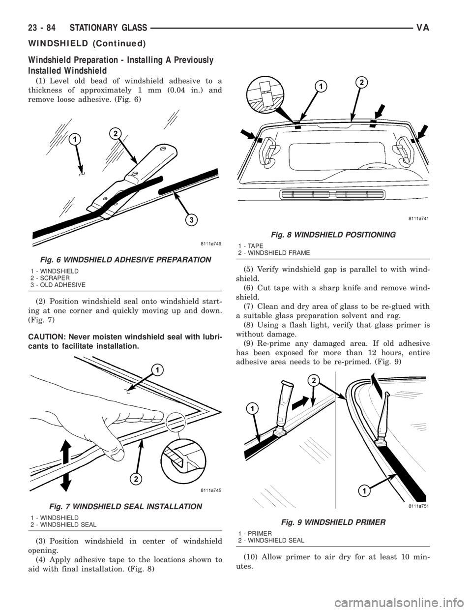
remove loose adhesive. (Fig. 6)
(2) Position windshield seal onto windshield start-
ing at one corner and quickly moving up and down.
(Fig. 7)
CAUTION: Never moisten windshield seal with lubri-
cants to facilitate installation.
(3) Position windshield in center of windshield
opening.
(4) Apply adhesive tape to the locations shown to
aid with final installation. (Fig. 8)(5) Verify windshield gap is parallel to with wind-
shield.
(6) Cut tape with a sharp knife and remove wind-
shield.
(7) Clean and dry area of glass to be re-glued with
a suitable glass preparation solvent and rag.
(8) Using a flash light, verify that glass primer is
without damage.
(9) Re-prime any damaged area. If old adhesive
has been exposed for more than 12 hours, entire
adhesive area needs to be re-primed. (Fig. 9)
(10) Allow primer to air dry for at least 10 min-
utes.
Fig. 6 WINDSHIELD ADHESIVE PREPARATION
1 - WINDSHIELD
2 - SCRAPER
3 - OLD ADHESIVE
Fig. 7 WINDSHIELD SEAL INSTALLATION
1 - WINDSHIELD
2 - WINDSHIELD SEAL
Fig. 8 WINDSHIELD POSITIONING
1 - TAPE
2 - WINDSHIELD FRAME
Fig. 9 WINDSHIELD PRIMER
1 - PRIMER
2 - WINDSHIELD SEAL
23 - 84 STATIONARY GLASSVA
WINDSHIELD (Continued)
Page 1123 of 1232
(11) Using a flash light, verify that glass primer is
without damage.
Windshield Preparation - Installing A New
Windshield
(1) Clean and check windshield for damage.
(2) Position windshield seal onto windshield start-
ing at one corner and quickly moving up and down.
(Fig. 7)
CAUTION: Never moisten windshield seal with lubri-
cants to facilitate installation.
(3) Position windshield in center of windshield
opening.
(4) Apply adhesive tape to the locations shown to
aid with final installation. (Fig. 8)
(5) Verify windshield gap is parallel to with wind-
shield.
(6) Cut tape with a sharp knife and remove wind-
shield.
(7) Clean and dry area of glass to be glued with a
suitable glass preparation solvent and rag.
(8) Apply primer to gluing surface at windshield
seal. (Fig. 9)
(9) Allow primer to air dry for at least 10 minutes.
(10) Using a flash light, verify that glass primer is
without damage.
Windshield Opening Preparation
(1) Clean and vacuum windshield opening.
(2) Level old bead of windshield opening adhesive
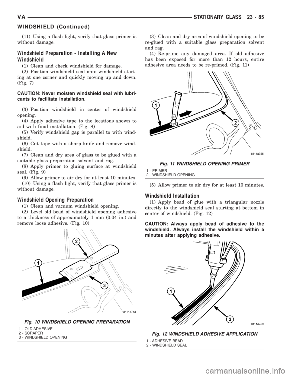
to a thickness of approximately 1 mm (0.04 in.) and
remove loose adhesive. (Fig. 10)(3) Clean and dry area of windshield opening to be
re-glued with a suitable glass preparation solvent
and rag.
(4) Re-prime any damaged area. If old adhesive
has been exposed for more than 12 hours, entire
adhesive area needs to be re-primed. (Fig. 11)
(5) Allow primer to air dry for at least 10 minutes.
Windshield Installation
(1) Apply bead of glue with a triangular nozzle
directly to the windshield seal starting at bottom in
center of windshield. (Fig. 12)
CAUTION: Always apply bead of adhesive to the
windshield. Always install the windshield within 5
minutes after applying adhesive.
Fig. 10 WINDSHIELD OPENING PREPARATION
1 - OLD ADHESIVE
2 - SCRAPER
3 - WINDSHIELD OPENING
Fig. 11 WINDSHIELD OPENING PRIMER
1 - PRIMER
2 - WINDSHIELD OPENING
Fig. 12 WINDSHIELD ADHESIVE APPLICATION
1 - ADHESIVE BEAD
2 - WINDSHIELD SEAL
VASTATIONARY GLASS 23 - 85
WINDSHIELD (Continued)
Page 1132 of 1232
c. With the engine running, duct temperature
should not be less than 2É C (35É F) or than 12É C
(54É F).
(7) If the compressor has not cycled off and the
duct temperature is less than 2É C (35É F) , check the
evaporator temperature sensor and circuit by per-
forming the ATC Function Test (Refer to 24 - HEAT-
ING & AIR CONDITIONING - DIAGNOSIS AND
TESTING).
(8) If duct output temperature is not within speci-
fications, check the refrigerant system for leaks and
proper refrigerant charge (Refer to 24 - HEATING &
AIR CONDITIONING/PLUMBING - DIAGNOSIS
AND TESTING) and (Refer to 24 - HEATING & AIR
CONDITIONING/PLUMBING - STANDARD PRO-
CEDURE).
DIAGNOSIS AND TESTING - HEATER
PERFORMANCE
Before performing the following tests, perform the
ATC Function Test using the DRBIIItand refer toCooling for the procedures to check the radiator cool-
ant level, serpentine drive belt tension, radiator air
flow and the radiator fan operation.
MAXIMUM HEATER OUTPUT
Engine coolant is provided to the heater core
through a heater valve and heater hose. With the
engine idling at normal operating temperature, set
the heater-A/C controls as follows:
²Temperature control in the full hot position
²Mode control in the floor heat position
²Blower motor control in the highest speed posi-
tion
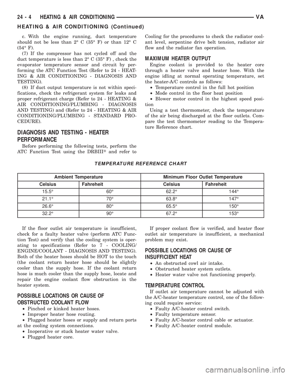
Using a test thermometer, check the temperature
of the air being discharged at the floor outlets. Com-
pare the test thermometer reading to the Tempera-
ture Reference chart.
TEMPERATURE REFERENCE CHART
Ambient Temperature Minimum Floor Outlet Temperature
Celsius Fahreheit Celsius Fahreheit
15.5É 60É 62.2É 144É
21.1É 70É 63.8É 147É
26.6É 80É 65.5É 150É
32.2É 90É 67.2É 153É
If the floor outlet air temperature is insufficient,
check for a faulty heater valve (perform ATC Func-
tion Test) and verify that the cooling system is oper-
ating to specifications (Refer to 7 - COOLING/
ENGINE/COOLANT - DIAGNOSIS AND TESTING).
Both of the heater hoses should be HOT to the touch
(the coolant return heater hose should be slightly
cooler than the supply hose. If the coolant return
hose is much cooler than the supply hose, locate and
repair the engine coolant flow obstruction in the
heater system.
POSSIBLE LOCATIONS OR CAUSE OF
OBSTRUCTED COOLANT FLOW
²Pinched or kinked heater hoses.
²Improper heater hose routing.
²Plugged heater hoses or supply and return ports
at the cooling system connections.
²Inoperative or stuck heater water valve.
²Plugged heater core.If proper coolant flow is verified, and heater floor
outlet air temperature is insufficient, a mechanical
problem may exist.
POSSIBLE LOCATIONS OR CAUSE OF
INSUFFICIENT HEAT
²An obstructed cowl air intake.
²Obstructed heater system outlets.
²Heater water valve not functioning properly.
TEMPERATURE CONTROL
If outlet air temperature cannot be adjusted with
the A/C-heater temperature control, one of the follow-
ing could require service:
²Faulty A/C-heater control switch.
²Faulty temperature sensor.
²Faulty A/C-heater control cable or actuator.
²Faulty A/C-heater control module.
24 - 4 HEATING & AIR CONDITIONINGVA
HEATING & AIR CONDITIONING (Continued)
Page 1138 of 1232
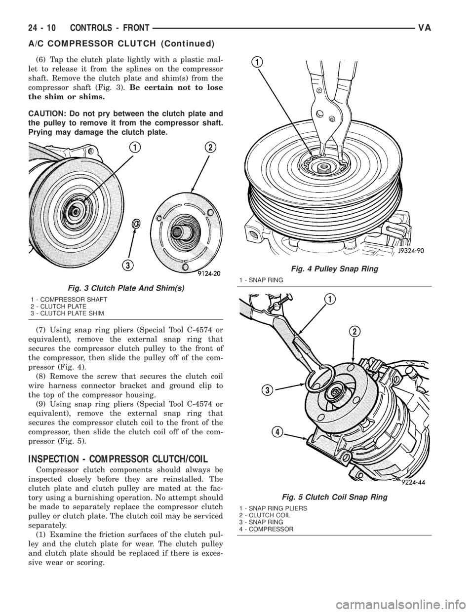
(6) Tap the clutch plate lightly with a plastic mal-
let to release it from the splines on the compressor
shaft. Remove the clutch plate and shim(s) from the
compressor shaft (Fig. 3).Be certain not to lose
the shim or shims.
CAUTION: Do not pry between the clutch plate and
the pulley to remove it from the compressor shaft.
Prying may damage the clutch plate.
(7) Using snap ring pliers (Special Tool C-4574 or
equivalent), remove the external snap ring that
secures the compressor clutch pulley to the front of
the compressor, then slide the pulley off of the com-
pressor (Fig. 4).
(8) Remove the screw that secures the clutch coil
wire harness connector bracket and ground clip to
the top of the compressor housing.
(9) Using snap ring pliers (Special Tool C-4574 or
equivalent), remove the external snap ring that
secures the compressor clutch coil to the front of the
compressor, then slide the clutch coil off of the com-
pressor (Fig. 5).
INSPECTION - COMPRESSOR CLUTCH/COIL
Compressor clutch components should always be
inspected closely before they are reinstalled. The
clutch plate and clutch pulley are mated at the fac-
tory using a burnishing operation. No attempt should
be made to separately replace the compressor clutch
pulley or clutch plate. The clutch coil may be serviced
separately.
(1) Examine the friction surfaces of the clutch pul-
ley and the clutch plate for wear. The clutch pulley
and clutch plate should be replaced if there is exces-
sive wear or scoring.
Fig. 3 Clutch Plate And Shim(s)
1 - COMPRESSOR SHAFT
2 - CLUTCH PLATE
3 - CLUTCH PLATE SHIM
Fig. 4 Pulley Snap Ring
1 - SNAP RING
Fig. 5 Clutch Coil Snap Ring
1 - SNAP RING PLIERS
2 - CLUTCH COIL
3 - SNAP RING
4 - COMPRESSOR
24 - 10 CONTROLS - FRONTVA
A/C COMPRESSOR CLUTCH (Continued)
Page 1151 of 1232
DIAGNOSIS AND TESTING
Before testing the rear blower motor switch, verify
that the front A/C system is functional by performing
the ATC Fuction Test using the DRBIIItscan tool.
Use a volt/ohmmeter to test the rear blower motor
switch. For circuit descriptions and diagrams, refer
to the appropriate wiring information. The wiring
information includes wiring diagrams, proper wire
and connector repair procedures, details of wire har-
ness routing and retention, connector pin-out infor-
mation and location views for the various wire
harness connectors, splices and grounds.
WARNING: ON VEHICLES EQUIPPED WITH AIR-
BAGS, DISABLE THE AIRBAG SYSTEM BEFORE
ATTEMPTING ANY STEERING WHEEL, STEERING
COLUMN, OR INSTRUMENT PANEL COMPONENT
DIAGNOSIS OR SERVICE. DISCONNECT AND ISO-
LATE THE BATTERY NEGATIVE (GROUND) CABLE,
THEN WAIT TWO MINUTES FOR THE AIRBAG SYS-
TEM CAPACITOR TO DISCHARGE BEFORE PER-
FORMING FURTHER DIAGNOSIS OR SERVICE. THIS
IS THE ONLY SURE WAY TO DISABLE THE AIRBAG
SYSTEM. FAILURE TO TAKE THE PROPER PRE-
CAUTIONS COULD RESULT IN ACCIDENTAL AIR-
BAG DEPLOYMENT AND POSSIBLE PERSONAL
INJURY.
(1) Disconnect and isolate the battery negative
cable.
(2) Unplug the wire harness connector from the
rear blower motor switch.
(3) Check for continuity between terminal 10 and
terminals 1, 7 and 4 of the blower motor switch. In
all instances, there should be continuity.
NOTE: To check the switch's internal circuits, con-
nect the negative lead of the ohmmeter to terminal
10 and the positive ohmmeter lead to terminals 1, 7
and 4. To check the switch's integral light emitting
diodes, reverse the ohmmeter leads.
(4) Check for continuity between the rear blower
motor switch terminals 3 and 7 as you move the
blower motor switch to each of the two speed posi-
tions, and the Off position. There should be continu-
ity in only one blower motor switch speed position.
(5) Check for continuity between the rear blower
motor switch terminals 4 and 8 as you move the
blower motor switch to each of the two speed posi-
tions, and the Off position. There should be continu-
ity in only the other blower motor switch speed
position.
(6) If OK, test and repair the rear blower motor
switch wire harness circuits. If not OK, replace the
faulty rear blower motor switch.
REMOVAL
NOTE: The rear blower motor switch is used only
on models with the optional rear A/C unit.
(1) Disconnect and isolate the battery negative
cable.
(2) Remove the blower motor switch from the
switch panel.
(3) Disconnect the wire harness connector from the
rear blower motor switch and remove the switch from
the vehicle.
INSTALLATION
(1) Connect the wire harness connector to the rear
blower motor switch.
(2) Install the blower motor switch into the switch
panel.
(3) Reconnect the battery negative cable.
BLOWER MOTOR RELAY
DESCRIPTION
The blower motor relays are an International Stan-
dards Organization (ISO)-type relay. The relays are
electro-mechanical devices which when energized,
directs fused battery current to the rear blower
motor. The relay coils are energized when they
receives a voltage signal from the blower motor
switch.
OPERATION
When the rear blower motor switch is in the low
speed position, the switch directs a voltage signal to
the high side of rear blower relay #1 and energizes
its relay coil. When energized, the low side of blower
relay #1 directs fused battery current through an
integral blower resistor to the rear blower motor.
When in the high speed position, the rear blower
switch directs a voltage signal to the high side of
rear blower relay #2 and energizes its relay coil.
When energized, the low side of blower relay #2
directs fused battery current through an integral
blower resistor to the rear blower motor.
The rear blower motor relays are located in the
relay block of the rear evaporator housing. Refer to
the appropriate wiring diagrams for more informa-
tion.
The blower motor relay cannot be repaired and, if
faulty or damaged, it must be replaced.
VACONTROLS - REAR 24 - 23
BLOWER MOTOR SWITCH (Continued)
Page 1152 of 1232
DIAGNOSIS AND TESTING
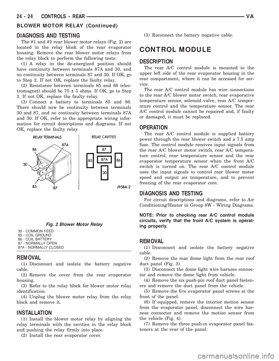
The #1 and #2 rear blower motor relays (Fig. 2) are
located in the relay block of the rear evaporator
housing. Remove the rear blower motor relays from
the relay block to perform the following tests:
(1) A relay in the de-energized position should
have continuity between terminals 87A and 30, and
no continuity between terminals 87 and 30. If OK, go
to Step 2. If not OK, replace the faulty relay.
(2) Resistance between terminals 85 and 86 (elec-
tromagnet) should be 75 5 ohms. If OK, go to Step
3. If not OK, replace the faulty relay.
(3) Connect a battery to terminals 85 and 86.
There should now be continuity between terminals
30 and 87, and no continuity between terminals 87A
and 30. If OK, refer to the appropriate wiring infor-
mation for circuit descriptions and diagrams. If not
OK, replace the faulty relay.
REMOVAL
(1) Disconnect and isolate the battery negative
cable.
(2) Remove the cover from the rear evaporator
housing.
(3) Refer to the relay block for blower motor relay
identification.
(4) Unplug the blower motor relay from the relay
block and remove it.
INSTALLATION
(1) Install the blower motor relay by aligning the
relay terminals with the cavities in the relay block
and pushing the relay firmly into place.
(2) Install the rear evaporator cover.(3) Reconnect the battery negative cable.
CONTROL MODULE
DESCRIPTION
The rear A/C control module is mounted to the
upper left side of the rear evaporator housing in the
rear compartment, where it can be accessed for ser-
vice.
The rear A/C control module has wire connections
to the rear A/C blower motor switch, rear evaporative
temperature sensor, solenoid valve, rear A/C temper-
ature control and the temperature sensor. The rear
A/C control module cannot be repaired and, if faulty
or damaged, it must be replaced.
OPERATION
The rear A/C control module is supplied battery
power through the rear blower switch and a 7.5 amp
fuse. The control module receives input signals from
the rear A/C blower motor switch, rear A/C tempera-
ture control, rear temperature sensor and the rear
evaporator temperature sensor when the front A/C
switch is turned on. The rear A/C control module
uses the input signals to control rear blower motor
speed and output air temperature, and to prevent
freezing of the rear evaporator core.
DIAGNOSIS AND TESTING
For circuit descriptions and diagrams, refer to Air
Conditioning/Heater in Group 8W - Wiring Diagrams.
NOTE: Prior to checking rear A/C control module
circuits, verify that the front A/C system is operat-
ing properly.
REMOVAL
(1) Disconnect and isolate the battery negative
cable.
(2) Remove the rear dome light from the rear roof
duct panel (Fig. 3).
(3) Disconnect the dome light wire harness connec-
tor and remove the dome light from vehicle.
(4) Remove the six push-pin roof duct panel fasten-
ers and remove the duct panel from the vehicle.
(5) Remove the five evaporator panel screws at the
front of the panel.
(6) If equipped, remove the interior motion sensor
from the evaporator panel, disconnect the wire har-
ness connector and remove the motion sensor from
the vehicle (Fig. 4).
(7) Remove the three push-in evaporator panel fas-
teners at the rear of the panel.
Fig. 2 Blower Motor Relay
30 - COMMON FEED
85 - COIL GROUND
86 - COIL BATTERY
87 - NORMALLY OPEN
87A - NORMALLY CLOSED
24 - 24 CONTROLS - REARVA
BLOWER MOTOR RELAY (Continued)
Page 1153 of 1232
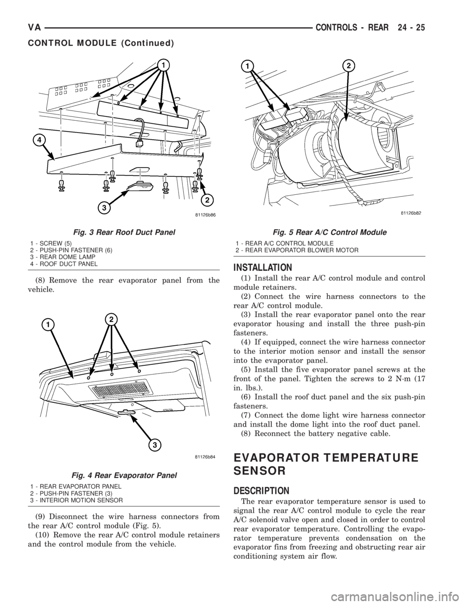
(8) Remove the rear evaporator panel from the
vehicle.
(9) Disconnect the wire harness connectors from
the rear A/C control module (Fig. 5).
(10) Remove the rear A/C control module retainers
and the control module from the vehicle.
INSTALLATION
(1) Install the rear A/C control module and control
module retainers.
(2) Connect the wire harness connectors to the
rear A/C control module.
(3) Install the rear evaporator panel onto the rear
evaporator housing and install the three push-pin
fasteners.
(4) If equipped, connect the wire harness connector
to the interior motion sensor and install the sensor
into the evaporator panel.
(5) Install the five evaporator panel screws at the
front of the panel. Tighten the screws to 2 N´m (17
in. lbs.).
(6) Install the roof duct panel and the six push-pin
fasteners.
(7) Connect the dome light wire harness connector
and install the dome light into the roof duct panel.
(8) Reconnect the battery negative cable.
EVAPORATOR TEMPERATURE
SENSOR
DESCRIPTION
The rear evaporator temperature sensor is used to
signal the rear A/C control module to cycle the rear
A/C solenoid valve open and closed in order to control
rear evaporator temperature. Controlling the evapo-
rator temperature prevents condensation on the
evaporator fins from freezing and obstructing rear air
conditioning system air flow.
Fig. 3 Rear Roof Duct Panel
1 - SCREW (5)
2 - PUSH-PIN FASTENER (6)
3 - REAR DOME LAMP
4 - ROOF DUCT PANEL
Fig. 4 Rear Evaporator Panel
1 - REAR EVAPORATOR PANEL
2 - PUSH-PIN FASTENER (3)
3 - INTERIOR MOTION SENSOR
Fig. 5 Rear A/C Control Module
1 - REAR A/C CONTROL MODULE
2 - REAR EVAPORATOR BLOWER MOTOR
VACONTROLS - REAR 24 - 25
CONTROL MODULE (Continued)