2005 MERCEDES-BENZ SPRINTER light
[x] Cancel search: lightPage 736 of 1232
OPERATION
The power outlet base or receptacle shell is con-
nected to ground, and an insulated contact in the
bottom of the shell is connected to battery current.
The power outlet receives battery voltage from a fuse
in the fuse block at all times.
DIAGNOSIS AND TESTING - POWER OUTLET
(1) Check for battery voltage at the fused B(+) fuse
in the fuse block. If OK, go to Step 2. If not OK,
repair the open fused B(+) circuit to the battery as
required.
(2) Check for continuity between the inside cir-
cumference of the power outlet receptacle and a good
ground. There should be continuity. If OK, go to Step
3. If not OK, go to Step 4.
(3) Check for battery voltage at the insulated con-
tact located at the back of the power outlet recepta-
cle. If not OK, go to Step 4.
(4) Disconnect and isolate the battery negative
cable. Check for continuity between the ground cir-
cuit cavity of the power outlet wire harness connector
and a good ground. There should be continuity. If
OK, go to Step 5. If not OK, repair the open ground
circuit to ground as required.
(5) Connect the battery negative cable. Check for
battery voltage at the fused B(+) circuit cavity of the
power outlet wire harness connector. If OK, replace
the faulty power outlet receptacle. If not OK, repair
the open fused B(+) circuit to the fuse in the fuse
block as required.
REMOVAL
(1) Disconnect and isolate the battery negative
cable.
(2) Pull the cigar lighter knob and element out of
the cigar lighter receptacle base, or unsnap the pro-
tective cap from the power outlet receptacle base.
(3) Look inside the cigar lighter or power outlet
receptacle base and note the position of the rectangu-
lar retaining bosses of the mount that secures the
receptacle base to the instrument panel.
(4) Insert a pair of external snap ring pliers into
the cigar lighter or power outlet receptacle base and
engage the tips of the pliers with the retaining
bosses of the mount.
(5) Squeeze the pliers to disengage the mount
retaining bosses from the receptacle base and, using
a gentle rocking motion, pull the pliers and the
receptacle base out of the mount.
(6) Disconnect the instrument panel wire harness
connector from the connector receptacle of the cigar
lighter or the power outlet receptacle base.
(7) Remove the cigar lighter or power outlet mount
from the instrument panel.
INSTALLATION
(1) Install the cigar lighter or power outlet mount
into the instrument panel.
(2) Reconnect the instrument panel wire harness
connector to the connector receptacle of the cigar
lighter or the power outlet receptacle base.
(3) Align the splines on the outside of the cigar
lighter or power outlet receptacle base connector
receptacle with the grooves on the inside of the
mount.
(4) Press firmly on the cigar lighter or power out-
let receptacle base until the retaining bosses of the
mount are fully engaged in their receptacles.
(5) Install the cigar lighter knob and element into
the cigar lighter receptacle base.
(6) Reconnect the battery negative cable.
RELAY
DESCRIPTION
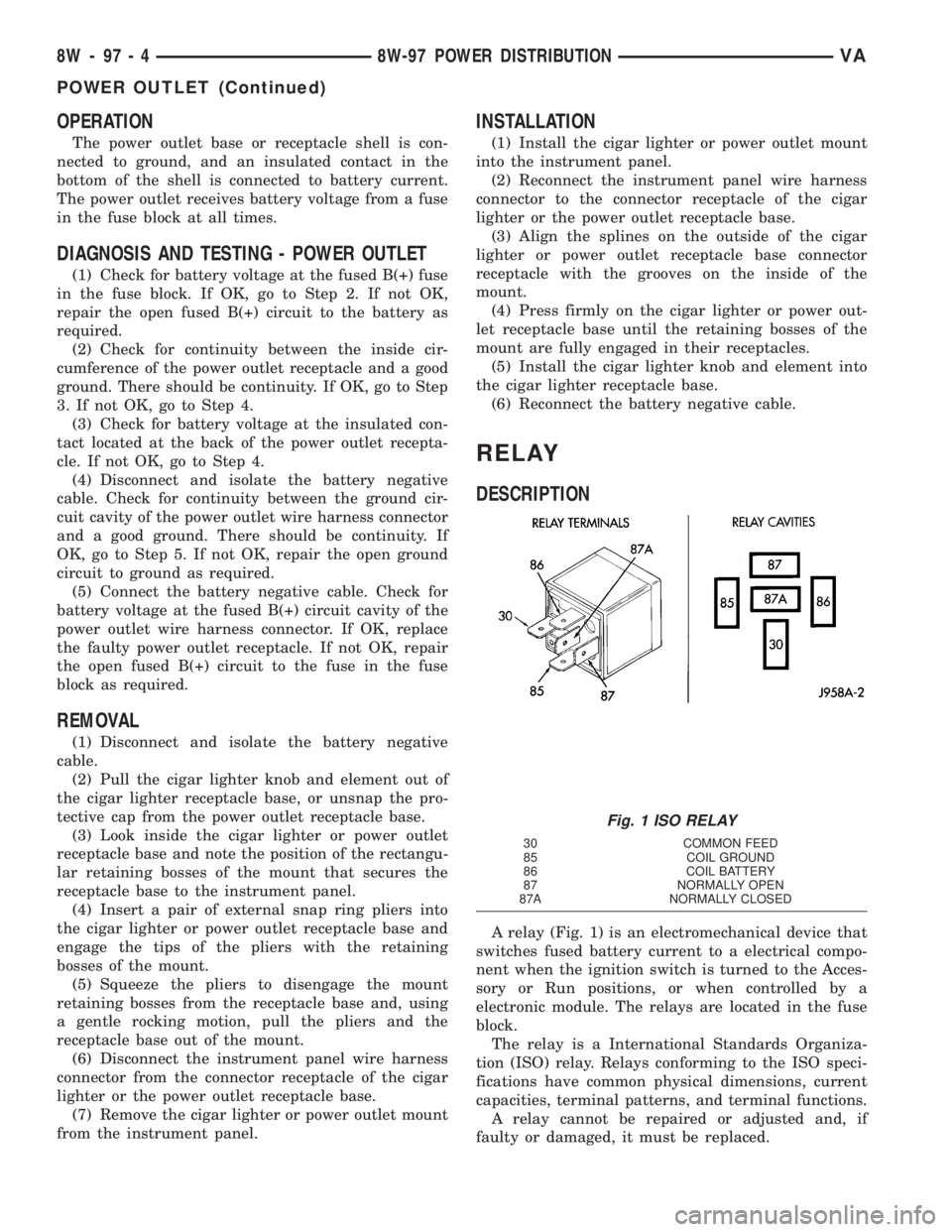
A relay (Fig. 1) is an electromechanical device that
switches fused battery current to a electrical compo-
nent when the ignition switch is turned to the Acces-
sory or Run positions, or when controlled by a
electronic module. The relays are located in the fuse
block.
The relay is a International Standards Organiza-
tion (ISO) relay. Relays conforming to the ISO speci-
fications have common physical dimensions, current
capacities, terminal patterns, and terminal functions.
A relay cannot be repaired or adjusted and, if
faulty or damaged, it must be replaced.
Fig. 1 ISO RELAY
30 COMMON FEED
85 COIL GROUND
86 COIL BATTERY
87 NORMALLY OPEN
87A NORMALLY CLOSED
8W - 97 - 4 8W-97 POWER DISTRIBUTIONVA
POWER OUTLET (Continued)
Page 737 of 1232
OPERATION
The ISO relay consists of an electromagnetic coil, a
resistor and three (two fixed and one movable) elec-
trical contacts. The movable (common feed) relay con-
tact is held against one of the fixed contacts
(normally closed) by spring pressure. When the elec-
tromagnetic coil is energized, it draws the movable
contact away from the normally closed fixed contact,
and holds it against the other (normally open) fixed
contact.
When the electromagnetic coil is de-energized,
spring pressure returns the movable contact to the
normally closed position. The resistor is connected in
parallel with the electromagnetic coil in the relay,
and helps to dissipate voltage spikes that are pro-
duced when the coil is de-energized.
DIAGNOSIS AND TESTING - RELAY
(1) Remove the relay from its mounting location.
(2) A relay in the de-energized position should
have continuity between terminals 87A and 30, and
no continuity between terminals 87 and 30. If OK, go
to Step 3. If not OK, replace the faulty relay.
(3) Resistance between terminals 85 and 86 (elec-
tromagnet) should be 60.7 - 80.3 ohms. If OK, go to
Step 4. If not OK, replace the faulty relay.
(4) Connect a battery to terminals 85 and 86.
There should now be continuity between terminals
30 and 87, and no continuity between terminals 87A
and 30. If OK, perform the Relay Circuit Test that
follows. If not OK, replace the faulty relay.
DIAGNOSIS AND TESTING - RELAY CIRCUIT TEST
(1) The relay common feed terminal cavity (30) of
the fuse block is connected to battery voltage and
should be hot at all times. Check for battery voltage
at the fused B(+) circuit cavity in the fuse block
receptacle for the relay. If OK, go to Step 2. If not
OK, repair the fused B(+) circuit to the fuse block
fuse as required.
(2) The relay normally closed terminal (87A) is
connected to terminal 30 in the de-energized position,
but is not used for this application. Go to Step 3.(3) The relay normally open terminal (87) is con-
nected to the common feed terminal (30) in the ener-
gized position. This terminal supplies battery voltage
to the fused B(+) fuse in the fuse block that feeds the
accessory when the relay is energized by the ignition
switch. There should be continuity between the fuse
block cavity for relay terminal 87 and the fused B(+)
fuse in the fuse block at all times. If OK, go to Step
4. If not OK, repair the open fused B(+) circuit to the
fuse block fuse as required.
(4) The coil ground terminal (85) is connected to
the electromagnet in the relay. It receives battery
feed to energize the relay when the ignition switch is
in the Accessory or Run positions. Turn the ignition
switch to the On position. Check for battery voltage
at the fused ignition switch output (acc/run) circuit
cavity for relay terminal 85 in the fuse block recep-
tacle for the relay. If OK, go to Step 5. If not OK,
repair the open fused ignition switch output (acc/run)
circuit to the ignition switch as required.
(5) The coil battery terminal (86) is connected to
the electromagnet in the relay. The fuse block cavity
for this terminal should have continuity to ground at
all times. If not OK, repair the open ground circuit to
ground as required.
REMOVAL
(1) Disconnect and isolate the negative battery
cable.
(2) Remove the relay by grasping it firmly and
pulling it straight out from its receptacle. A slight
back and fourth rocking motion may help the
removal process.
INSTALLATION
(1) Position the relay to the proper receptacle.
(2) Align the relay terminals with the terminal
cavities in the receptacle.
(3) Push firmly and evenly on the top of the relay
until the terminals are fully seated in the terminal
cavities in the receptacle.
(4) Connect the negative battery cable.
VA8W-97 POWER DISTRIBUTION 8W - 97 - 5
RELAY (Continued)
Page 772 of 1232
ENGINE BLOCK
STANDARD PROCEDURE
STANDARD PROCEDURE - REPLACING ENGINE
CORE AND OIL GALLERY PLUGS
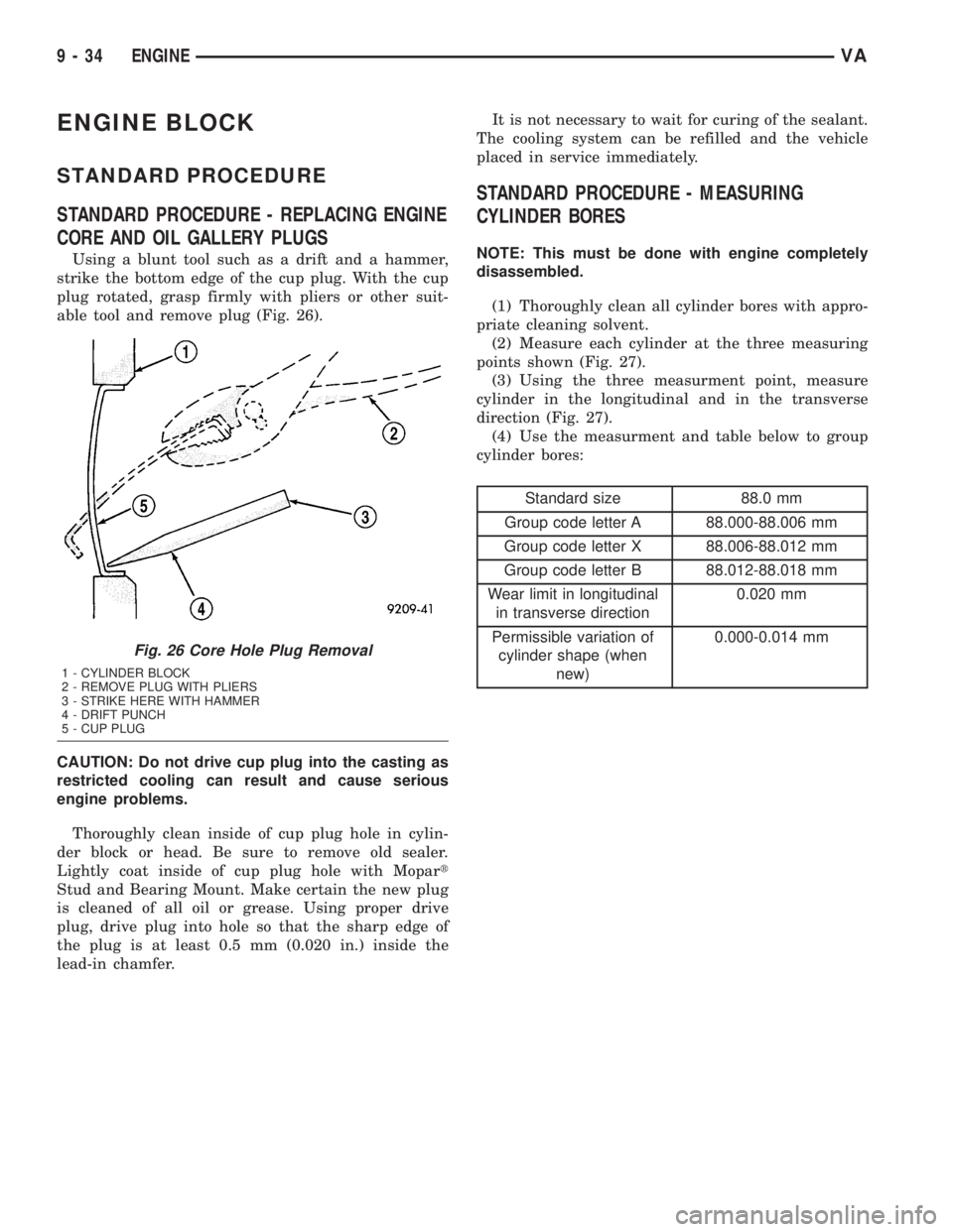
Using a blunt tool such as a drift and a hammer,
strike the bottom edge of the cup plug. With the cup
plug rotated, grasp firmly with pliers or other suit-
able tool and remove plug (Fig. 26).
CAUTION: Do not drive cup plug into the casting as
restricted cooling can result and cause serious
engine problems.
Thoroughly clean inside of cup plug hole in cylin-
der block or head. Be sure to remove old sealer.
Lightly coat inside of cup plug hole with Mopart
Stud and Bearing Mount. Make certain the new plug
is cleaned of all oil or grease. Using proper drive
plug, drive plug into hole so that the sharp edge of
the plug is at least 0.5 mm (0.020 in.) inside the
lead-in chamfer.It is not necessary to wait for curing of the sealant.
The cooling system can be refilled and the vehicle
placed in service immediately.
STANDARD PROCEDURE - MEASURING
CYLINDER BORES
NOTE: This must be done with engine completely
disassembled.
(1) Thoroughly clean all cylinder bores with appro-
priate cleaning solvent.
(2) Measure each cylinder at the three measuring
points shown (Fig. 27).
(3) Using the three measurment point, measure
cylinder in the longitudinal and in the transverse
direction (Fig. 27).
(4) Use the measurment and table below to group
cylinder bores:
Standard size 88.0 mm
Group code letter A 88.000-88.006 mm
Group code letter X 88.006-88.012 mm
Group code letter B 88.012-88.018 mm
Wear limit in longitudinal
in transverse direction0.020 mm
Permissible variation of
cylinder shape (when
new)0.000-0.014 mm
Fig. 26 Core Hole Plug Removal
1 - CYLINDER BLOCK
2 - REMOVE PLUG WITH PLIERS
3 - STRIKE HERE WITH HAMMER
4 - DRIFT PUNCH
5 - CUP PLUG
9 - 34 ENGINEVA
Page 787 of 1232
INSTALLATION
(1) Clean all sealing surfaces.
(2) Position driver on rear of pump and install vac-
uum pump with new seals. Tighten bolts to 14N´m
(124 lbs. in.). (Fig. 44)
(3) Install vacuum line to vacuum pump (Fig. 44).
(4) Connect negative battery cable.
WARNING: USE EXTREME CAUTION WHEN THE
ENGINE IS OPERATING. DO NOT STAND IN A
DIRECT LINE WITH THE FAN. DO NOT PUT YOUR
HANDS NEAR THE PULLEYS, BELTS OR FAN. DO
NOT WEAR LOOSE CLOTHES.
(5) Start the engine and inspect for leaks.
LEFT MOUNT
REMOVAL
(1) Install engine support fixture #8534 with adap-
tors #8534±16 and raise the engine slightly.
(2) Raise and support the vehicle.
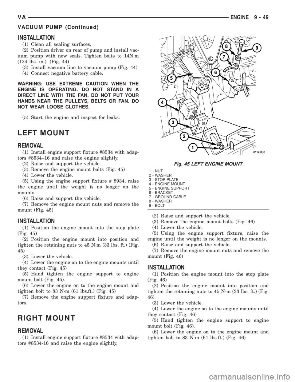
(3) Remove the engine mount bolts (Fig. 45)
(4) Lower the vehicle.
(5) Using the engine support fixture # 8934, raise
the engine until the weight is no longer on the
mounts.
(6) Raise and support the vehicle.
(7) Remove the engine mount nuts and remove the
mount (Fig. 45)
INSTALLATION
(1) Position the engine mount into the stop plate
(Fig. 45)
(2) Position the engine mount into position and
tighten the retaining nuts to 45 N´m (33 lbs. ft.) (Fig.
45)
(3) Lower the vehicle.
(4) Lower the engine on to the engine mounts until
they contact (Fig. 45)
(5) Hand tighten the engine support to engine
mount bolt (Fig. 45).
(6) Lower the engine on to the engine mount and
tighten bolt to 83 N´m (61 lbs.ft.) (Fig. 45)
(7) Remove the engine support fixture and adap-
tors.
RIGHT MOUNT
REMOVAL
(1) Install engine support fixture #8534 with adap-
tors #8534-16 and raise the engine slightly.(2) Raise and support the vehicle.
(3) Remove the engine mount bolts (Fig. 46)
(4) Lower the vehicle.
(5) Using the engine support fixture, raise the
engine until the weight is no longer on the mounts.
(6) Raise and support the vehicle.
(7) Remove the engine mount nuts and remove the
mount (Fig. 46)
INSTALLATION
(1) Position the engine mount into the stop plate
(Fig. 46)
(2) Position the engine mount into position and
tighten the retaining nuts to 45 N´m (33 lbs. ft.) (Fig.
46)
(3) Lower the vehicle.
(4) Lower the engine on to the engine mounts until
they contact (Fig. 46)
(5) Hand tighten the engine support to engine
mount bolt (Fig. 46).
(6) Lower the engine on to the engine mount and
tighten bolt to 83 N´m (61 lbs.ft.) (Fig. 46)
Fig. 45 LEFT ENGINE MOUNT
1 - NUT
2 - WASHER
3 - STOP PLATE
4 - ENGINE MOUNT
5 - ENGINE SUPPORT
6 - BRACKET
7 - GROUND CABLE
8 - WASHER
9 - BOLT
VAENGINE 9 - 49
VACUUM PUMP (Continued)
Page 790 of 1232
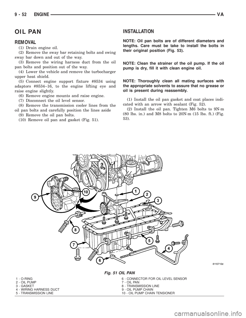
OIL PAN
REMOVAL
(1) Drain engine oil.
(2) Remove the sway bar retaining bolts and swing
sway bar down and out of the way.
(3) Remove the wiring harness duct from the oil
pan bolts and position out of the way.
(4) Lower the vehicle and remove the turbocharger
upper heat shield.
(5) Connect engine support fixture #8534 using
adaptors #8534±16, to the engine lifting eye and
raise engine slightly.
(6) Remove engine mounts and raise engine.
(7) Disconnect the oil level sensor.
(8) Remove the transmission cooler lines from the
oil pan bolts and carefully position the lines aside
(9) Remove the oil pan bolts.
(10) Remove oil pan and gasket (Fig. 51).
INSTALLATION
NOTE: Oil pan bolts are of different diameters and
lengths. Care must be take to install the bolts in
their original position (Fig. 53).
NOTE: Clean the strainer of the oil pump. If the oil
pump is dry, fill it with clean engine oil.
NOTE: Thoroughly clean all mating surfaces with
the appropriate solvents to assure that no grease or
oil is present during reassembly.
(1) Install the oil pan gasket and coat places indi-
cated with an arrow with sealant (Fig. 52).
(2) Install the oil pan. Tighten M6 bolts to 9N´m
(80 lbs. in.) and M8 bolts to 20N´m (15 lbs. ft.) (Fig.
53).
Fig. 51 OIL PAN
1 - O-RING 6 - CONNECTOR FOR OIL LEVEL SENSOR
2 - OIL PUMP 7 - OIL PAN
3 - GASKET 8 - TRANSMISSION LINE
4 - WIRING HARNESS DUCT 9 - OIL PUMP CHAIN
5 - TRANSMISSION LINE 10 - OIL PUMP CHAIN TENSIONER
9 - 52 ENGINEVA
Page 811 of 1232
EXHAUST SYSTEM
TABLE OF CONTENTS
page page
EXHAUST SYSTEM
DESCRIPTION - 2.7L DIESEL...............1
DIAGNOSIS AND TESTING - DIESEL ENGINE . . 2
CATALYTIC CONVERTER
REMOVAL.............................3
INSTALLATION..........................3
EXHAUST PIPE
REMOVAL.............................3
INSTALLATION..........................3
TAILPIPE
REMOVAL.............................3
INSTALLATION..........................3
TURBOCHARGER SYSTEM
DESCRIPTION..........................3
OPERATION............................4
CHARGE AIR COOLER AND PLUMBING
DESCRIPTION..........................4OPERATION............................4
DIAGNOSIS AND TESTING - CHARGE AIR
COOLER SYSTEM - LEAKS...............4
REMOVAL.............................5
CLEANING.............................5
INSPECTION...........................5
INSTALLATION..........................5
TURBOCHARGER
DESCRIPTION..........................6
OPERATION............................6
REMOVAL
REMOVAL............................7
REMOVAL - VACUUM TRANSDUCER.......7
INSTALLATION
INSTALLATION........................8
INSTALLATION - VACUUM TRANSDUCER . . . 8
EXHAUST SYSTEM
DESCRIPTION - 2.7L DIESEL
CAUTION: Avoid application of rust prevention com-
pounds or undercoating materials to exhaust sys-
tem floor pan exhaust heat shields. Light overspray
near the edges is permitted. Application of coating
will result in excessive floor pan temperatures and
objectionable fumes.
The diesel engine exhaust system consists of an
engine exhaust manifold, turbocharger, exhaust pipe,
resonator, extension pipe (if needed), muffler and
exhaust tailpipe (Fig. 1).The exhaust system must be properly aligned and
secured to prevent stress, leakage and body contact.
The exhaust components should be kept a minimum
of 25.4 mm (1.0 in.) away from the body and frame.
If the system contacts any body panel, it may amplify
objectionable noises from the engine or body.
VAEXHAUST SYSTEM 11 - 1
Page 814 of 1232
²Higher torque as a result of improved cylinder
charge.
²Reduction in exhaust emissions as a result of an
improvement in the air supply of the engine.
²Increased power output as a result of the higher
charge pressure combined with a reduced exhaust
backpressure and thus improved charge cycle.
OPERATION
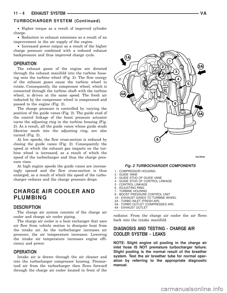
The exhaust gases of the engine are directed
through the exhaust manifold into the turbine hous-
ing onto the turbine wheel (Fig. 2). The flow energy
of the exhaust gases cause the turbine wheel to
rotate. Consequently, the compressor wheel, which is
connected through the turbine shaft with the turbine
wheel, is driven at the same speed. The fresh air
inducted by the compressor wheel is compressed and
passed to the engine (Fig. 2).
The charge pressure is controlled by varying the
position of the guide vanes (Fig. 2). The guide stud of
the control linkage of the boost pressure actuator
turns the adjusting ring in the turbine housing (Fig.
2). As a result, all the guide vanes whose guide studs
likewise mesh into the adjusting ring, are also
turned (Fig. 2).
At low speeds, the flow cross-section is reduced by
closing the guide vanes (Fig. 2). Consequently the
speed at which the exhaust gas impacts on the tur-
bine wheel is increased, as a result of which the
speed of the turbocharger and thus the charge pres-
sure rises.
At high engine speeds the guide vanes are increas-
ingly opened and the flow cross-section is thus
enlarged, as a result of which the speed of the turbo-
charger reduces and the charge pressure drops.
CHARGE AIR COOLER AND
PLUMBING
DESCRIPTION
The charge air system consists of the charge air
cooler and charge air cooler piping.
The charge air cooler is a heat exchanger that uses
air flow from vehicle motion to dissipate heat from
the intake air. As the turbocharger increases air
pressure, the air temperature increases. Lowering
the intake air temperature increases engine effi-
ciency and power.
OPERATION
Intake air is drawn through the air cleaner and
into the turbocharger compressor housing. Pressur-
ized air from the turbocharger then flows forward
through the charge air cooler located in front of theradiator. From the charge air cooler the air flows
back into the intake manifold.
DIAGNOSIS AND TESTING - CHARGE AIR
COOLER SYSTEM - LEAKS
NOTE: Slight engine oil pooling in the charge air
inlet hose IS NOT premature turbocharger failure.
Slight pooling is the normal result of the breather
system. Test the air breather tube for normal oper-
ation by referring to the appropriate diagnostic
manual.
Fig. 2 TURBOCHARGER COMPONENTS
1 - COMPRESSOR HOUSING
2 - GUIDE VANE
3 - GUIDE STUD OF GUIDE VANE
4 - GUIDE STUD OF CONTROL LINKAGE
5 - CONTROL LINKAGE
6 - ADJUSTING RING
7 - TURBINE HOUSING
8 - BOOST PRESSURE CONTROL UNIT
1A - EXHAUST GASES TO TURBINE WHEEL
2A - TURBO INLET (FRESH AIR)
3A - TURBO OUTLET (COMPRESSED AIR)
4A - EXHAUST OUTLET
11 - 4 EXHAUST SYSTEMVA
TURBOCHARGER SYSTEM (Continued)
Page 815 of 1232
Low turbocharger boost pressure and low engine
performance can be caused by leaks in the charge air
cooler or it's plumbing. The following procedure out-
lines how to check for leaks in the charge air cooler
system.
(1) Loosen clamp and remove turbocharger to air
inlet duct rubber sleeve from turbocharger.
(2) Insert Special Tool 8442 Adapter into the rub-
ber sleeve. Tighten existing clamp to 8 N´m (72
in.lbs.).
CAUTION: Do not apply more than 138 kpa (20 psi)
air pressure to the charge air cooler system, sever
damage to the charge air cooler system may occur.
(3) Connect regulated air supply to air fitting on
Special Tool 8442 Adapter. Set air pressure to a Max-
imum of 138 kpa (20 psi).
(4) Using soapy water check the air inlet ducts,
rubber sleeves, charge air cooler and intake manifold
for leaks.
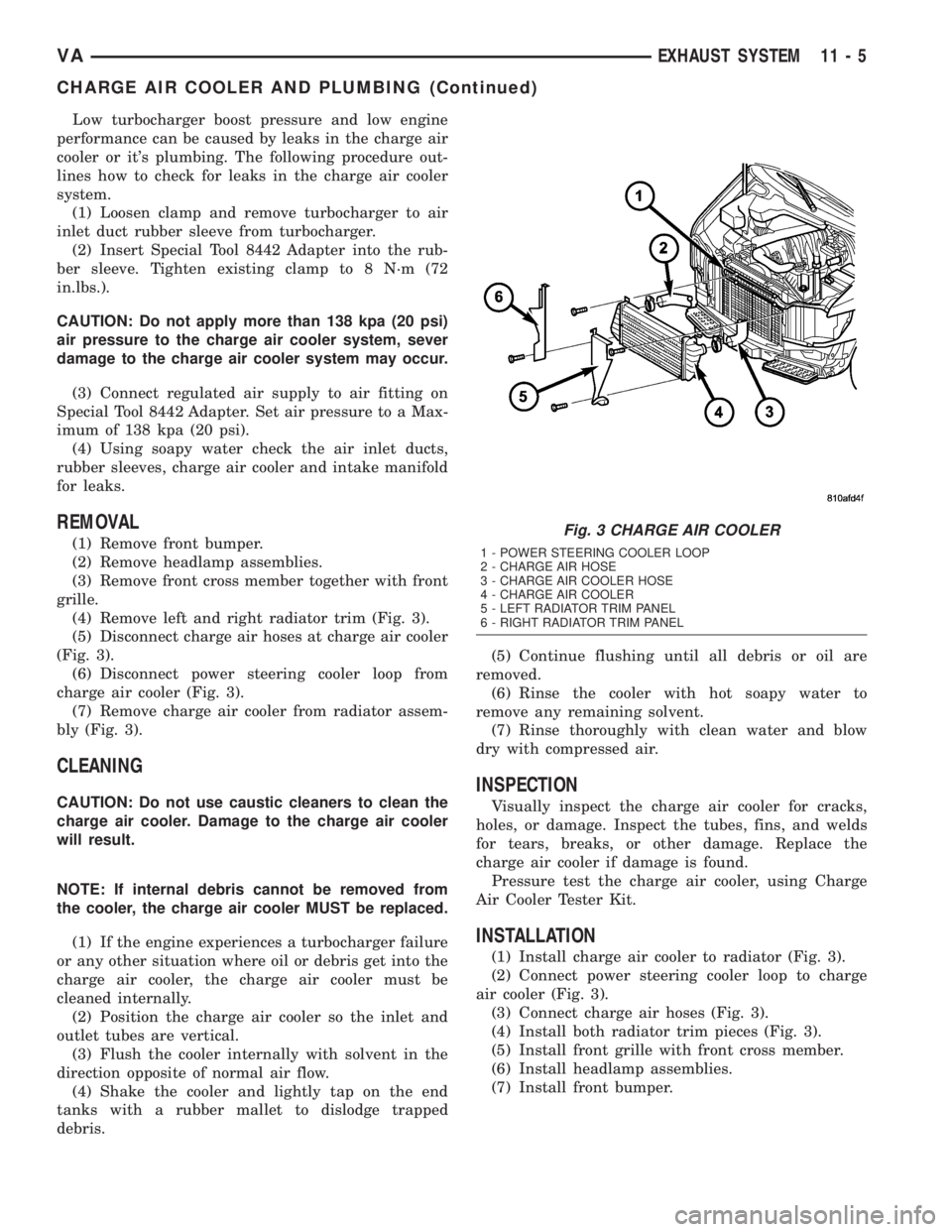
REMOVAL
(1) Remove front bumper.
(2) Remove headlamp assemblies.
(3) Remove front cross member together with front
grille.
(4) Remove left and right radiator trim (Fig. 3).
(5) Disconnect charge air hoses at charge air cooler
(Fig. 3).
(6) Disconnect power steering cooler loop from
charge air cooler (Fig. 3).
(7) Remove charge air cooler from radiator assem-
bly (Fig. 3).
CLEANING
CAUTION: Do not use caustic cleaners to clean the
charge air cooler. Damage to the charge air cooler
will result.
NOTE: If internal debris cannot be removed from
the cooler, the charge air cooler MUST be replaced.
(1) If the engine experiences a turbocharger failure
or any other situation where oil or debris get into the
charge air cooler, the charge air cooler must be
cleaned internally.
(2) Position the charge air cooler so the inlet and
outlet tubes are vertical.
(3) Flush the cooler internally with solvent in the
direction opposite of normal air flow.
(4) Shake the cooler and lightly tap on the end
tanks with a rubber mallet to dislodge trapped
debris.(5) Continue flushing until all debris or oil are
removed.
(6) Rinse the cooler with hot soapy water to
remove any remaining solvent.
(7) Rinse thoroughly with clean water and blow
dry with compressed air.
INSPECTION
Visually inspect the charge air cooler for cracks,
holes, or damage. Inspect the tubes, fins, and welds
for tears, breaks, or other damage. Replace the
charge air cooler if damage is found.
Pressure test the charge air cooler, using Charge
Air Cooler Tester Kit.
INSTALLATION
(1) Install charge air cooler to radiator (Fig. 3).
(2) Connect power steering cooler loop to charge
air cooler (Fig. 3).
(3) Connect charge air hoses (Fig. 3).
(4) Install both radiator trim pieces (Fig. 3).
(5) Install front grille with front cross member.
(6) Install headlamp assemblies.
(7) Install front bumper.
Fig. 3 CHARGE AIR COOLER
1 - POWER STEERING COOLER LOOP
2 - CHARGE AIR HOSE
3 - CHARGE AIR COOLER HOSE
4 - CHARGE AIR COOLER
5 - LEFT RADIATOR TRIM PANEL
6 - RIGHT RADIATOR TRIM PANEL
VAEXHAUST SYSTEM 11 - 5
CHARGE AIR COOLER AND PLUMBING (Continued)