2005 MERCEDES-BENZ SPRINTER light
[x] Cancel search: lightPage 842 of 1232
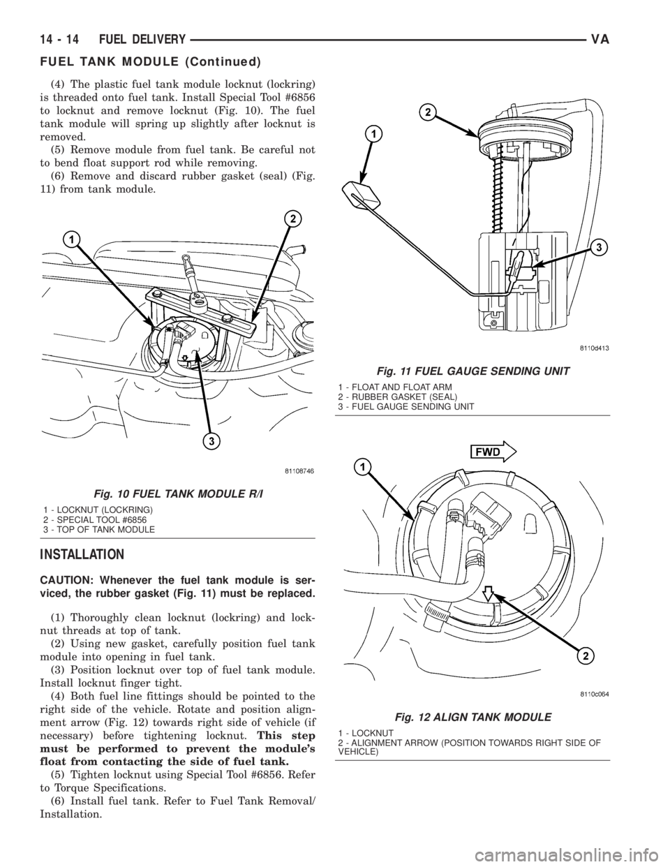
(4) The plastic fuel tank module locknut (lockring)
is threaded onto fuel tank. Install Special Tool #6856
to locknut and remove locknut (Fig. 10). The fuel
tank module will spring up slightly after locknut is
removed.
(5) Remove module from fuel tank. Be careful not
to bend float support rod while removing.
(6) Remove and discard rubber gasket (seal) (Fig.
11) from tank module.
INSTALLATION
CAUTION: Whenever the fuel tank module is ser-
viced, the rubber gasket (Fig. 11) must be replaced.
(1) Thoroughly clean locknut (lockring) and lock-
nut threads at top of tank.
(2) Using new gasket, carefully position fuel tank
module into opening in fuel tank.
(3) Position locknut over top of fuel tank module.
Install locknut finger tight.
(4) Both fuel line fittings should be pointed to the
right side of the vehicle. Rotate and position align-
ment arrow (Fig. 12) towards right side of vehicle (if
necessary) before tightening locknut.This step
must be performed to prevent the module's
float from contacting the side of fuel tank.
(5) Tighten locknut using Special Tool #6856. Refer
to Torque Specifications.
(6) Install fuel tank. Refer to Fuel Tank Removal/
Installation.
Fig. 10 FUEL TANK MODULE R/I
1 - LOCKNUT (LOCKRING)
2 - SPECIAL TOOL #6856
3 - TOP OF TANK MODULE
Fig. 11 FUEL GAUGE SENDING UNIT
1 - FLOAT AND FLOAT ARM
2 - RUBBER GASKET (SEAL)
3 - FUEL GAUGE SENDING UNIT
Fig. 12 ALIGN TANK MODULE
1 - LOCKNUT
2 - ALIGNMENT ARROW (POSITION TOWARDS RIGHT SIDE OF
VEHICLE)
14 - 14 FUEL DELIVERYVA
FUEL TANK MODULE (Continued)
Page 848 of 1232
CRANKSHAFT POSITION
SENSOR
DESCRIPTION
The crankshaft position sensor is located opposite
the teeth on the flywheel and uses a non contact
method to record the position of the crankshaft. The
leading edges of each tooth on the flywheel generate
a positive signal in the position sensor, while the
trailing edges generate a negative signal. When the
crankshaft is rotating, an alternating voltage is pro-
duced as a result.
The period of the signal is the time required by the
crankshaft to turn through the gap between two fly-
wheel teeth. The clearance between the crankshaft
position sensor and the teeth of the flywheel is fixed
by the installation.
Two teeth on the flywheel are missing. The result-
ing signal gap is used by the ECM to detect the TDC
position of cylinder number one.
OPERATION
The clearance between the crankshaft position sen-
sor and the flywheel are fixed by the installation
position. Two teeth on the flywheel are missing. The
resulting gap is used by the ECM to detect DTC of
cylinder number one. The crankshaft position is cal-
culated to an accuracy of a fraction of a degree so
that the start and end of injection can occur at
exactly the right moment. The engine speed signal is
also processed by the ECM from the crankshaft sen-
sor. This signal is then transferred to other control
modules over the CAN bus.
If the crankshaft position sensor fails, the signal
that provides reference rotation is missing. Injection
may occur at the wrong time and damage the engine.
In this case, the ECM will stop triggering the injec-
tors, the engine would cut out, the engine warning
light would illuminate and the engine will not
restart.
REMOVAL
(1) Disconnect the negative battery cable.
(2) Unplug the crankshaft wiring harness connec-
tor.
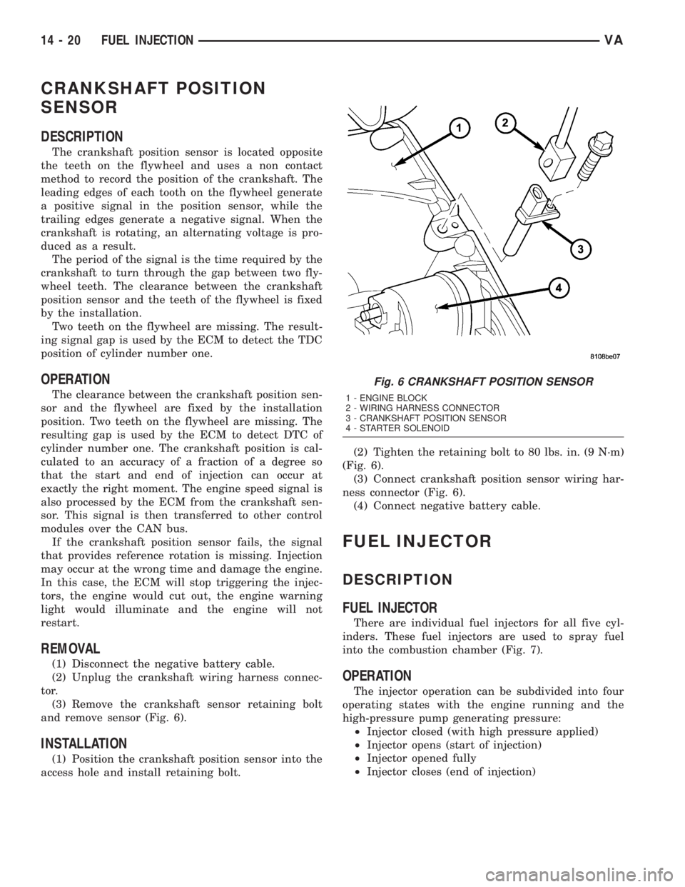
(3) Remove the crankshaft sensor retaining bolt
and remove sensor (Fig. 6).
INSTALLATION
(1) Position the crankshaft position sensor into the
access hole and install retaining bolt.(2) Tighten the retaining bolt to 80 lbs. in. (9 N´m)
(Fig. 6).
(3) Connect crankshaft position sensor wiring har-
ness connector (Fig. 6).
(4) Connect negative battery cable.
FUEL INJECTOR
DESCRIPTION
FUEL INJECTOR
There are individual fuel injectors for all five cyl-
inders. These fuel injectors are used to spray fuel
into the combustion chamber (Fig. 7).
OPERATION
The injector operation can be subdivided into four
operating states with the engine running and the
high-pressure pump generating pressure:
²Injector closed (with high pressure applied)
²Injector opens (start of injection)
²Injector opened fully
²Injector closes (end of injection)
Fig. 6 CRANKSHAFT POSITION SENSOR
1 - ENGINE BLOCK
2 - WIRING HARNESS CONNECTOR
3 - CRANKSHAFT POSITION SENSOR
4 - STARTER SOLENOID
14 - 20 FUEL INJECTIONVA
Page 855 of 1232
INSTALLATION
(1) (Refer to 14 - FUEL SYSTEM/FUEL INJEC-
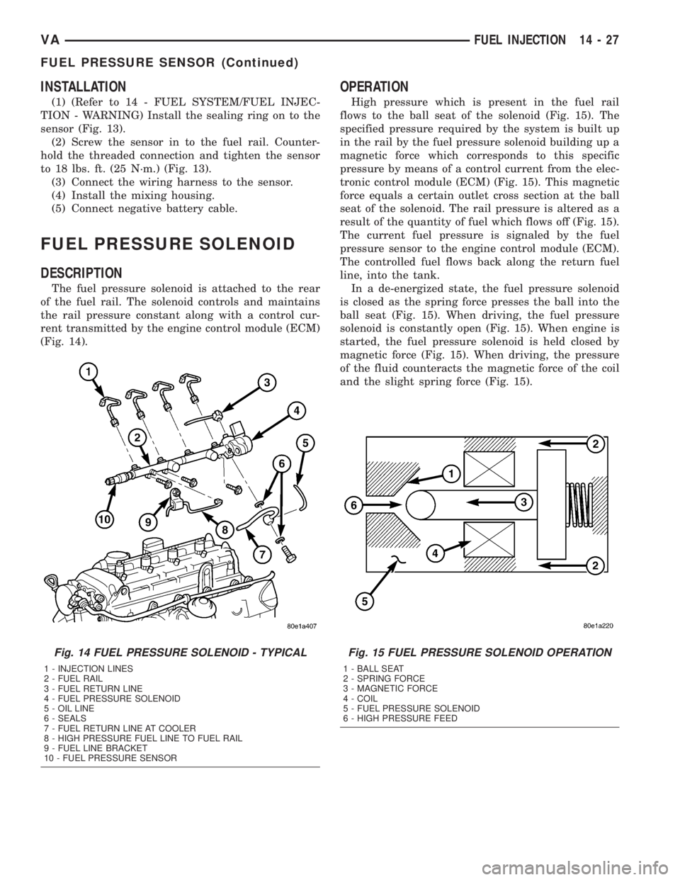
TION - WARNING) Install the sealing ring on to the
sensor (Fig. 13).
(2) Screw the sensor in to the fuel rail. Counter-
hold the threaded connection and tighten the sensor
to 18 lbs. ft. (25 N´m.) (Fig. 13).
(3) Connect the wiring harness to the sensor.
(4) Install the mixing housing.
(5) Connect negative battery cable.
FUEL PRESSURE SOLENOID
DESCRIPTION
The fuel pressure solenoid is attached to the rear
of the fuel rail. The solenoid controls and maintains
the rail pressure constant along with a control cur-
rent transmitted by the engine control module (ECM)
(Fig. 14).
OPERATION
High pressure which is present in the fuel rail
flows to the ball seat of the solenoid (Fig. 15). The
specified pressure required by the system is built up
in the rail by the fuel pressure solenoid building up a
magnetic force which corresponds to this specific
pressure by means of a control current from the elec-
tronic control module (ECM) (Fig. 15). This magnetic
force equals a certain outlet cross section at the ball
seat of the solenoid. The rail pressure is altered as a
result of the quantity of fuel which flows off (Fig. 15).
The current fuel pressure is signaled by the fuel
pressure sensor to the engine control module (ECM).
The controlled fuel flows back along the return fuel
line, into the tank.
In a de-energized state, the fuel pressure solenoid
is closed as the spring force presses the ball into the
ball seat (Fig. 15). When driving, the fuel pressure
solenoid is constantly open (Fig. 15). When engine is
started, the fuel pressure solenoid is held closed by
magnetic force (Fig. 15). When driving, the pressure
of the fluid counteracts the magnetic force of the coil
and the slight spring force (Fig. 15).
Fig. 14 FUEL PRESSURE SOLENOID - TYPICAL
1 - INJECTION LINES
2 - FUEL RAIL
3 - FUEL RETURN LINE
4 - FUEL PRESSURE SOLENOID
5 - OIL LINE
6 - SEALS
7 - FUEL RETURN LINE AT COOLER
8 - HIGH PRESSURE FUEL LINE TO FUEL RAIL
9 - FUEL LINE BRACKET
10 - FUEL PRESSURE SENSOR
Fig. 15 FUEL PRESSURE SOLENOID OPERATION
1 - BALL SEAT
2 - SPRING FORCE
3 - MAGNETIC FORCE
4 - COIL
5 - FUEL PRESSURE SOLENOID
6 - HIGH PRESSURE FEED
VAFUEL INJECTION 14 - 27
FUEL PRESSURE SENSOR (Continued)
Page 874 of 1232
SPECIFICATIONS - TORQUE CHART
TORQUE SPECIFICATIONS
DESCRIPTION N´m Ft. Lbs. In. Lbs.
Power Steering Pump To
Timing Case Cover/
Support21 15 185
High Pressure Flexible
Hose To Power Steering
Pump38 28 336
Power Steering Pulley To
Pump30 22 265
FLUID
STANDARD PROCEDURE
POWER STEERING PUMP FILL AND BLEED
PROCEDURE
(1) Remove the cap from the fluid reservoir.
Check cap seal for damage and replace if
needed.
(2) Fill the power steering pump with Mopar
ATF+4 Automatic Transmission fluid or equivalent.
Do not fill fluid beyond the MAX mark.
(3) Raise the vehicles front wheels off the ground.
(4) With the engine off turn the steering wheel
from right to left.Perform this step until all the
bubble formations can no longer be seen in the
power steering reservoir.
(5) Start the engine and turn the steering wheel
with the engine at idle speed then shut the engine off
and check for correct oil level and no bubble in the
system.
(6) Reinstall power steering cap tightly.
(7) Test the system for leaks and proper operation.
FLUID COOLER TUBE
REMOVAL
(1) Siphon as much power steering fluid as possi-
ble out of the reservoir.
(2) Remove the grille (Refer to 23 - BODY/EXTE-
RIOR/GRILLE - REMOVAL).
(3) Remove the left headlight assembly.
(4) Disconnect the return lines from the cooler
tube.
(5) Remove the radiator clips (2).
(6) Remove the heat shield bolt for the turbo at
the core support.
(7) Remove the right headlight assembly.(8) Remove the core support bolts (4) and discon-
nect the hood latch cable.
(9) Remove the fan bracket bolts (4) to the radiator
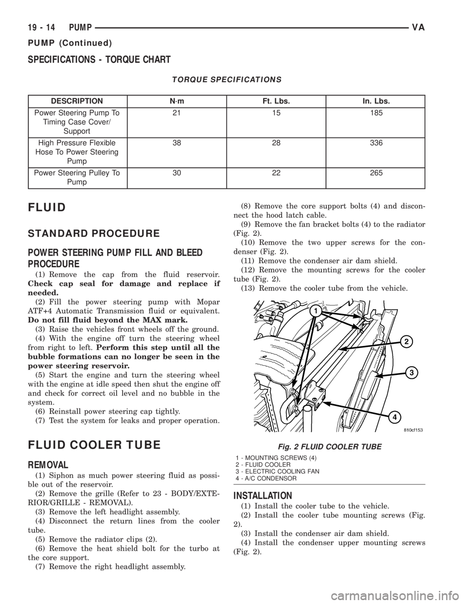
(Fig. 2).
(10) Remove the two upper screws for the con-
denser (Fig. 2).
(11) Remove the condenser air dam shield.
(12) Remove the mounting screws for the cooler
tube (Fig. 2).
(13) Remove the cooler tube from the vehicle.
INSTALLATION
(1) Install the cooler tube to the vehicle.
(2) Install the cooler tube mounting screws (Fig.
2).
(3) Install the condenser air dam shield.
(4) Install the condenser upper mounting screws
(Fig. 2).
Fig. 2 FLUID COOLER TUBE
1 - MOUNTING SCREWS (4)
2 - FLUID COOLER
3 - ELECTRIC COOLING FAN
4 - A/C CONDENSOR
19 - 14 PUMPVA
PUMP (Continued)
Page 875 of 1232
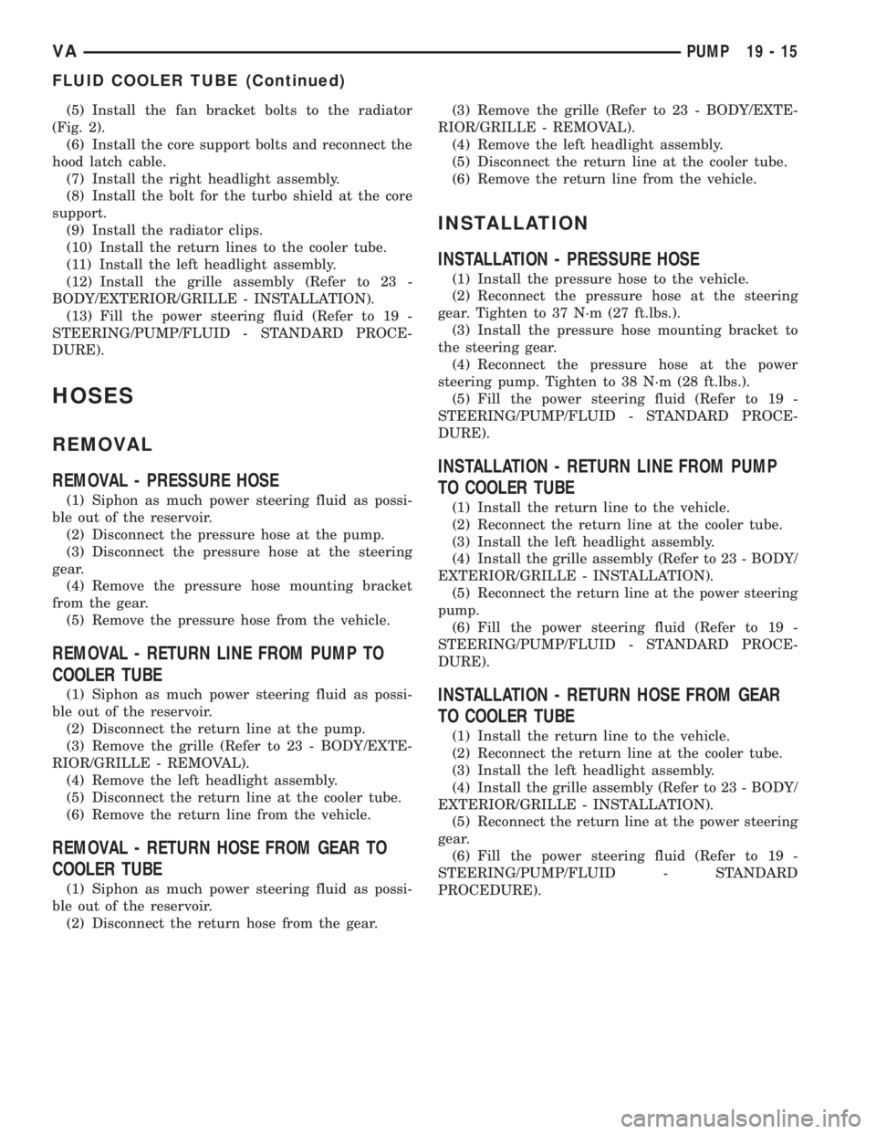
(5) Install the fan bracket bolts to the radiator
(Fig. 2).
(6) Install the core support bolts and reconnect the
hood latch cable.
(7) Install the right headlight assembly.
(8) Install the bolt for the turbo shield at the core
support.
(9) Install the radiator clips.
(10) Install the return lines to the cooler tube.
(11) Install the left headlight assembly.
(12) Install the grille assembly (Refer to 23 -
BODY/EXTERIOR/GRILLE - INSTALLATION).
(13) Fill the power steering fluid (Refer to 19 -
STEERING/PUMP/FLUID - STANDARD PROCE-
DURE).
HOSES
REMOVAL
REMOVAL - PRESSURE HOSE
(1) Siphon as much power steering fluid as possi-
ble out of the reservoir.
(2) Disconnect the pressure hose at the pump.
(3) Disconnect the pressure hose at the steering
gear.
(4) Remove the pressure hose mounting bracket
from the gear.
(5) Remove the pressure hose from the vehicle.
REMOVAL - RETURN LINE FROM PUMP TO
COOLER TUBE
(1) Siphon as much power steering fluid as possi-
ble out of the reservoir.
(2) Disconnect the return line at the pump.
(3) Remove the grille (Refer to 23 - BODY/EXTE-
RIOR/GRILLE - REMOVAL).
(4) Remove the left headlight assembly.
(5) Disconnect the return line at the cooler tube.
(6) Remove the return line from the vehicle.
REMOVAL - RETURN HOSE FROM GEAR TO
COOLER TUBE
(1) Siphon as much power steering fluid as possi-
ble out of the reservoir.
(2) Disconnect the return hose from the gear.(3) Remove the grille (Refer to 23 - BODY/EXTE-
RIOR/GRILLE - REMOVAL).
(4) Remove the left headlight assembly.
(5) Disconnect the return line at the cooler tube.
(6) Remove the return line from the vehicle.
INSTALLATION
INSTALLATION - PRESSURE HOSE
(1) Install the pressure hose to the vehicle.
(2) Reconnect the pressure hose at the steering
gear. Tighten to 37 N´m (27 ft.lbs.).
(3) Install the pressure hose mounting bracket to
the steering gear.
(4) Reconnect the pressure hose at the power
steering pump. Tighten to 38 N´m (28 ft.lbs.).
(5) Fill the power steering fluid (Refer to 19 -
STEERING/PUMP/FLUID - STANDARD PROCE-
DURE).
INSTALLATION - RETURN LINE FROM PUMP
TO COOLER TUBE
(1) Install the return line to the vehicle.
(2) Reconnect the return line at the cooler tube.
(3) Install the left headlight assembly.
(4) Install the grille assembly (Refer to 23 - BODY/
EXTERIOR/GRILLE - INSTALLATION).
(5) Reconnect the return line at the power steering
pump.
(6) Fill the power steering fluid (Refer to 19 -
STEERING/PUMP/FLUID - STANDARD PROCE-
DURE).
INSTALLATION - RETURN HOSE FROM GEAR
TO COOLER TUBE
(1) Install the return line to the vehicle.
(2) Reconnect the return line at the cooler tube.
(3) Install the left headlight assembly.
(4) Install the grille assembly (Refer to 23 - BODY/
EXTERIOR/GRILLE - INSTALLATION).
(5) Reconnect the return line at the power steering
gear.
(6) Fill the power steering fluid (Refer to 19 -
STEERING/PUMP/FLUID - STANDARD
PROCEDURE).
VAPUMP 19 - 15
FLUID COOLER TUBE (Continued)
Page 878 of 1232
OUTPUT SHAFT SEAL
REMOVAL............................125
INSTALLATION........................125
PARK LOCK CABLE
REMOVAL............................125
INSTALLATION........................126
PISTONS
DESCRIPTION........................128
OPERATION..........................128
PLANETARY GEARTRAIN
DESCRIPTION........................130
OPERATION..........................130
DISASSEMBLY........................131
ASSEMBLY...........................131
SHIFT MECHANISM
DESCRIPTION........................133
OPERATION..........................133
REMOVAL............................134
INSTALLATION........................135
SOLENOID
DESCRIPTION........................136OPERATION..........................138
TEMPERATURE SENSOR/PARK-NEUTRAL
CONTACT
DESCRIPTION
DESCRIPTION - PARK/NEUTRAL CONTACT . 139
DESCRIPTION - TRANSMISSION
TEMPERATURE SENSOR..............140
OPERATION
OPERATION - PARK/NEUTRAL CONTACT . . 140
OPERATION - TRANSMISSION
TEMPERATURE SENSOR..............141
TORQUE CONVERTER
DESCRIPTION........................141
OPERATION..........................143
REMOVAL............................146
INSTALLATION........................146
TORQUE CONVERTER HUB SEAL
REMOVAL............................147
INSTALLATION........................147
AUTOMATIC TRANSMISSION -
NAG1
DESCRIPTION
The NAG1 automatic transmission (Fig. 1) is an
electronically controlled 5-speed transmission with a
lock-up clutch in the torque converter. The ratios for
the gear stages are obtained by 3 planetary gear sets.
Fifth gear is designed as an overdrive with a high-
speed ratio.
The gears are actuated electronically/hydraulically.
The gears are shifted by means of an appropriate
combination of three multi-disc holding clutches,
three multi-disc driving clutches, and two freewheel-
ing clutches.
Electronic transmission control enables precise
adaptation of pressures to the respective operating
conditions and to the engine output during the shift
phase which results in a significant improvement in
shift quality.
Furthermore, it offers the advantage of a flexible
adaptation to various vehicle and engines.
Basically, the automatic transmission with elec-
tronic control offers the following advantages:
²Reduces fuel consumption.
²Improved shift comfort.
²More favourable step-up through the five gears.
²Increased service life and reliability.
²Lower maintenance costs.
TRANSMISSION IDENTIFICATION
The transmission name, NAG1, means New Auto-
matic Gearbox, generation 1.
The transmission can be generically identified
visually by the presence of a round 13-way connector
located near the front corner of the transmission oil
pan, on the right side. Specific transmission informa-
tion can be found stamped into a pad on the left side
of the transmission, above the oil pan rail.
TRANSMISSION GEAR RATIOS
The gear ratios for the NAG1 automatic transmis-
sion are as follows:
1st Gear.............................3.59:1
2nd Gear............................2.19:1
3rd Gear............................1.41:1
4th Gear............................1.00:1
5th Gear............................0.83:1
Reverse.............................3.16:1
TRANSMISSION HOUSING
The converter housing and transmission are made
from a light alloy. These are bolted together and cen-
tered via the outer multi-disc carrier of multi-disc
holding clutch, B1. A coated intermediate plate pro-
vides the sealing. The oil pump and the outer multi-
disc carrier of the multi-disc holding clutch, B1, are
bolted to the converter housing. The stator shaft is
pressed into it and prevented from rotating by
splines. The electrohydraulic unit is bolted to the
transmission housing from underneath. A sheet
metal steel oil pan forms the closure.
21 - 2 AUTOMATIC TRANSMISSION - NAG1VA
Page 879 of 1232
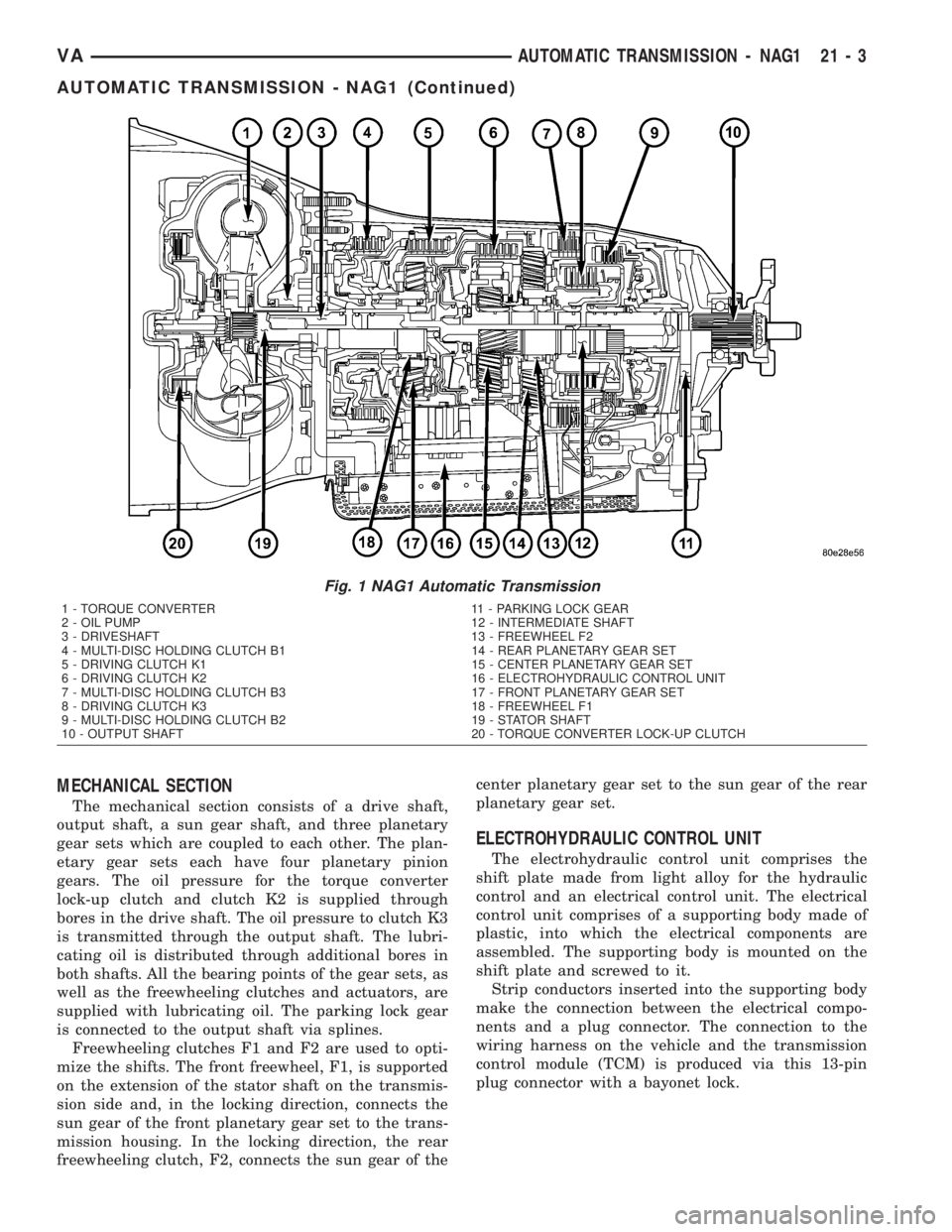
MECHANICAL SECTION
The mechanical section consists of a drive shaft,
output shaft, a sun gear shaft, and three planetary
gear sets which are coupled to each other. The plan-
etary gear sets each have four planetary pinion
gears. The oil pressure for the torque converter
lock-up clutch and clutch K2 is supplied through
bores in the drive shaft. The oil pressure to clutch K3
is transmitted through the output shaft. The lubri-
cating oil is distributed through additional bores in
both shafts. All the bearing points of the gear sets, as
well as the freewheeling clutches and actuators, are
supplied with lubricating oil. The parking lock gear
is connected to the output shaft via splines.
Freewheeling clutches F1 and F2 are used to opti-
mize the shifts. The front freewheel, F1, is supported
on the extension of the stator shaft on the transmis-
sion side and, in the locking direction, connects the
sun gear of the front planetary gear set to the trans-
mission housing. In the locking direction, the rear
freewheeling clutch, F2, connects the sun gear of thecenter planetary gear set to the sun gear of the rear
planetary gear set.
ELECTROHYDRAULIC CONTROL UNIT
The electrohydraulic control unit comprises the
shift plate made from light alloy for the hydraulic
control and an electrical control unit. The electrical
control unit comprises of a supporting body made of
plastic, into which the electrical components are
assembled. The supporting body is mounted on the
shift plate and screwed to it.
Strip conductors inserted into the supporting body
make the connection between the electrical compo-
nents and a plug connector. The connection to the
wiring harness on the vehicle and the transmission
control module (TCM) is produced via this 13-pin
plug connector with a bayonet lock.
Fig. 1 NAG1 Automatic Transmission
1 - TORQUE CONVERTER 11 - PARKING LOCK GEAR
2 - OIL PUMP 12 - INTERMEDIATE SHAFT
3 - DRIVESHAFT 13 - FREEWHEEL F2
4 - MULTI-DISC HOLDING CLUTCH B1 14 - REAR PLANETARY GEAR SET
5 - DRIVING CLUTCH K1 15 - CENTER PLANETARY GEAR SET
6 - DRIVING CLUTCH K2 16 - ELECTROHYDRAULIC CONTROL UNIT
7 - MULTI-DISC HOLDING CLUTCH B3 17 - FRONT PLANETARY GEAR SET
8 - DRIVING CLUTCH K3 18 - FREEWHEEL F1
9 - MULTI-DISC HOLDING CLUTCH B2 19 - STATOR SHAFT
10 - OUTPUT SHAFT 20 - TORQUE CONVERTER LOCK-UP CLUTCH
VAAUTOMATIC TRANSMISSION - NAG1 21 - 3
AUTOMATIC TRANSMISSION - NAG1 (Continued)
Page 905 of 1232
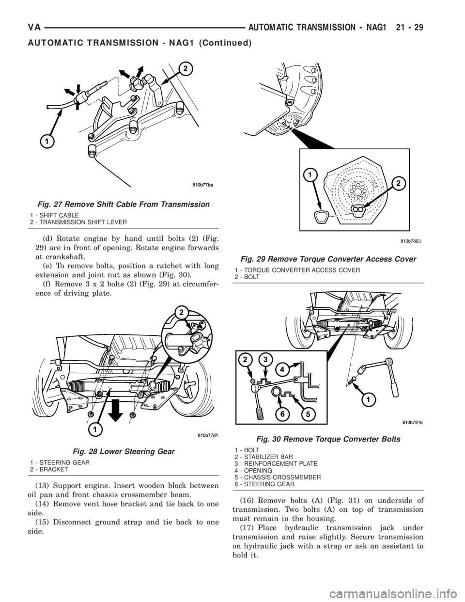
(d) Rotate engine by hand until bolts (2) (Fig.
29) are in front of opening. Rotate engine forwards
at crankshaft.
(e) To remove bolts, position a ratchet with long
extension and joint nut as shown (Fig. 30).
(f) Remove3x2bolts (2) (Fig. 29) at circumfer-
ence of driving plate.
(13) Support engine. Insert wooden block between
oil pan and front chassis crossmember beam.
(14) Remove vent hose bracket and tie back to one
side.
(15) Disconnect ground strap and tie back to one
side.(16) Remove bolts (A) (Fig. 31) on underside of
transmission. Two bolts (A) on top of transmission
must remain in the housing.
(17) Place hydraulic transmission jack under
transmission and raise slightly. Secure transmission
on hydraulic jack with a strap or ask an assistant to
hold it.
Fig. 27 Remove Shift Cable From Transmission
1 - SHIFT CABLE
2 - TRANSMISSION SHIFT LEVER
Fig. 28 Lower Steering Gear
1 - STEERING GEAR
2 - BRACKET
Fig. 29 Remove Torque Converter Access Cover
1 - TORQUE CONVERTER ACCESS COVER
2 - BOLT
Fig. 30 Remove Torque Converter Bolts
1 - BOLT
2 - STABILIZER BAR
3 - REINFORCEMENT PLATE
4 - OPENING
5 - CHASSIS CROSSMEMBER
6 - STEERING GEAR
VAAUTOMATIC TRANSMISSION - NAG1 21 - 29
AUTOMATIC TRANSMISSION - NAG1 (Continued)