2005 MERCEDES-BENZ SPRINTER light
[x] Cancel search: lightPage 1065 of 1232
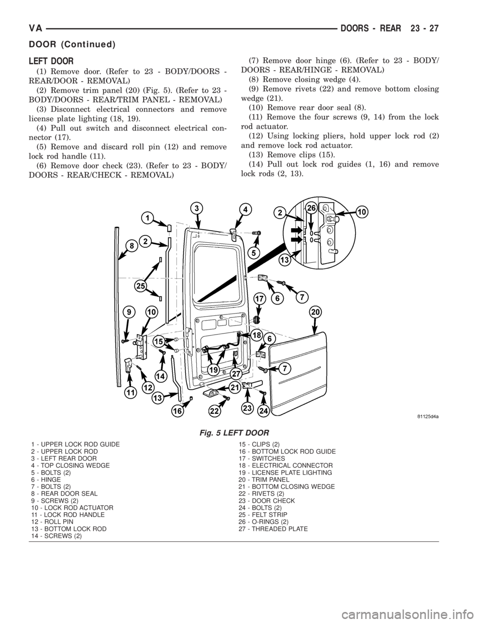
LEFT DOOR
(1) Remove door. (Refer to 23 - BODY/DOORS -
REAR/DOOR - REMOVAL)
(2) Remove trim panel (20) (Fig. 5). (Refer to 23 -
BODY/DOORS - REAR/TRIM PANEL - REMOVAL)
(3) Disconnect electrical connectors and remove
license plate lighting (18, 19).
(4) Pull out switch and disconnect electrical con-
nector (17).
(5) Remove and discard roll pin (12) and remove
lock rod handle (11).
(6) Remove door check (23). (Refer to 23 - BODY/
DOORS - REAR/CHECK - REMOVAL)(7) Remove door hinge (6). (Refer to 23 - BODY/
DOORS - REAR/HINGE - REMOVAL)
(8) Remove closing wedge (4).
(9) Remove rivets (22) and remove bottom closing
wedge (21).
(10) Remove rear door seal (8).
(11) Remove the four screws (9, 14) from the lock
rod actuator.
(12) Using locking pliers, hold upper lock rod (2)
and remove lock rod actuator.
(13) Remove clips (15).
(14) Pull out lock rod guides (1, 16) and remove
lock rods (2, 13).
Fig. 5 LEFT DOOR
1 - UPPER LOCK ROD GUIDE 15 - CLIPS (2)
2 - UPPER LOCK ROD 16 - BOTTOM LOCK ROD GUIDE
3 - LEFT REAR DOOR 17 - SWITCHES
4 - TOP CLOSING WEDGE 18 - ELECTRICAL CONNECTOR
5 - BOLTS (2) 19 - LICENSE PLATE LIGHTING
6 - HINGE 20 - TRIM PANEL
7 - BOLTS (2) 21 - BOTTOM CLOSING WEDGE
8 - REAR DOOR SEAL 22 - RIVETS (2)
9 - SCREWS (2) 23 - DOOR CHECK
10 - LOCK ROD ACTUATOR 24 - BOLTS (2)
11 - LOCK ROD HANDLE 25 - FELT STRIP
12 - ROLL PIN 26 - O-RINGS (2)
13 - BOTTOM LOCK ROD 27 - THREADED PLATE
14 - SCREWS (2)
VADOORS - REAR 23 - 27
DOOR (Continued)
Page 1067 of 1232
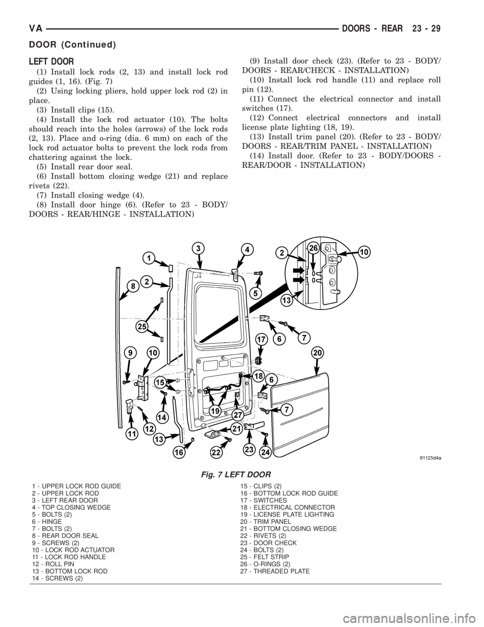
LEFT DOOR
(1) Install lock rods (2, 13) and install lock rod
guides (1, 16). (Fig. 7)
(2) Using locking pliers, hold upper lock rod (2) in
place.
(3) Install clips (15).
(4) Install the lock rod actuator (10). The bolts
should reach into the holes (arrows) of the lock rods
(2, 13). Place and o-ring (dia. 6 mm) on each of the
lock rod actuator bolts to prevent the lock rods from
chattering against the lock.
(5) Install rear door seal.
(6) Install bottom closing wedge (21) and replace
rivets (22).
(7) Install closing wedge (4).
(8) Install door hinge (6). (Refer to 23 - BODY/
DOORS - REAR/HINGE - INSTALLATION)(9) Install door check (23). (Refer to 23 - BODY/
DOORS - REAR/CHECK - INSTALLATION)
(10) Install lock rod handle (11) and replace roll
pin (12).
(11) Connect the electrical connector and install
switches (17).
(12) Connect electrical connectors and install
license plate lighting (18, 19).
(13) Install trim panel (20). (Refer to 23 - BODY/
DOORS - REAR/TRIM PANEL - INSTALLATION)
(14) Install door. (Refer to 23 - BODY/DOORS -
REAR/DOOR - INSTALLATION)
Fig. 7 LEFT DOOR
1 - UPPER LOCK ROD GUIDE 15 - CLIPS (2)
2 - UPPER LOCK ROD 16 - BOTTOM LOCK ROD GUIDE
3 - LEFT REAR DOOR 17 - SWITCHES
4 - TOP CLOSING WEDGE 18 - ELECTRICAL CONNECTOR
5 - BOLTS (2) 19 - LICENSE PLATE LIGHTING
6 - HINGE 20 - TRIM PANEL
7 - BOLTS (2) 21 - BOTTOM CLOSING WEDGE
8 - REAR DOOR SEAL 22 - RIVETS (2)
9 - SCREWS (2) 23 - DOOR CHECK
10 - LOCK ROD ACTUATOR 24 - BOLTS (2)
11 - LOCK ROD HANDLE 25 - FELT STRIP
12 - ROLL PIN 26 - O-RINGS (2)
13 - BOTTOM LOCK ROD 27 - THREADED PLATE
14 - SCREWS (2)
VADOORS - REAR 23 - 29
DOOR (Continued)
Page 1085 of 1232
EXTERIOR
TABLE OF CONTENTS
page page
FUEL FILL DOOR
REMOVAL.............................47
INSTALLATION.........................47
GRILLE
REMOVAL.............................47
INSTALLATION.........................47
LICENSE PLATE BRACKET
REMOVAL.............................47
INSTALLATION.........................47RADIATOR CROSSMEMBER
REMOVAL.............................47
INSTALLATION.........................48
SIDE VIEW MIRROR
REMOVAL.............................48
INSTALLATION.........................48
SIDE VIEW MIRROR - GLASS
REMOVAL.............................49
INSTALLATION.........................49
FUEL FILL DOOR
REMOVAL
(1) Open passenger compartment door.
(2) Open fuel fill door.
(3) Using a trim stick C-4755 or equivalent, dis-
connect the filler cap tether.
(4) Remove two bolts and remove filler door.
INSTALLATION
(1) Install the door and bolts.
(2) Connect filler cap tether.
(3) Close doors.
GRILLE
REMOVAL
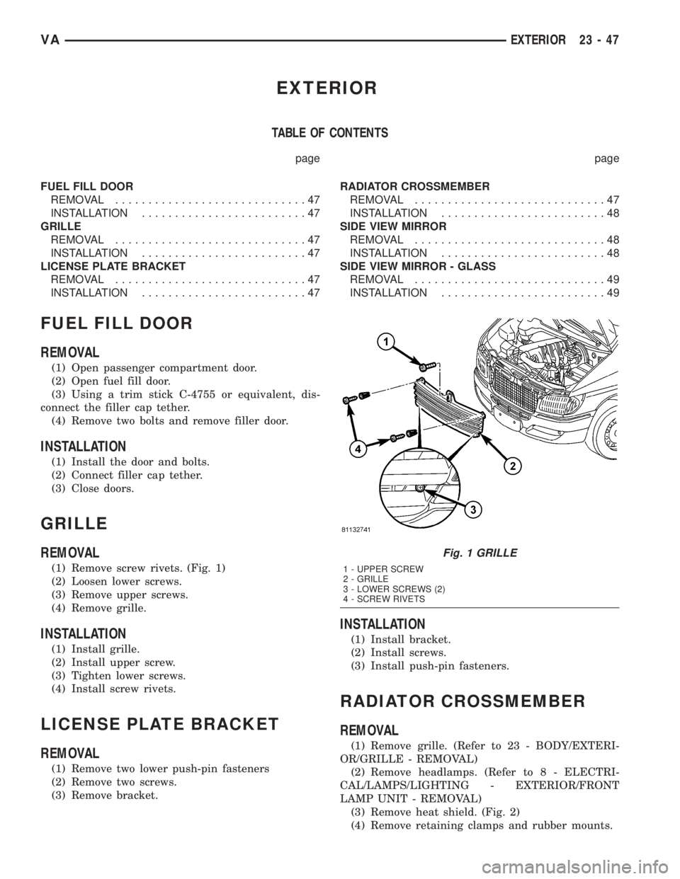
(1) Remove screw rivets. (Fig. 1)
(2) Loosen lower screws.
(3) Remove upper screws.
(4) Remove grille.
INSTALLATION
(1) Install grille.
(2) Install upper screw.
(3) Tighten lower screws.
(4) Install screw rivets.
LICENSE PLATE BRACKET
REMOVAL
(1) Remove two lower push-pin fasteners
(2) Remove two screws.
(3) Remove bracket.
INSTALLATION
(1) Install bracket.
(2) Install screws.
(3) Install push-pin fasteners.
RADIATOR CROSSMEMBER
REMOVAL
(1) Remove grille. (Refer to 23 - BODY/EXTERI-
OR/GRILLE - REMOVAL)
(2) Remove headlamps. (Refer to 8 - ELECTRI-
CAL/LAMPS/LIGHTING - EXTERIOR/FRONT
LAMP UNIT - REMOVAL)
(3) Remove heat shield. (Fig. 2)
(4) Remove retaining clamps and rubber mounts.
Fig. 1 GRILLE
1 - UPPER SCREW
2 - GRILLE
3 - LOWER SCREWS (2)
4 - SCREW RIVETS
VAEXTERIOR 23 - 47
Page 1086 of 1232
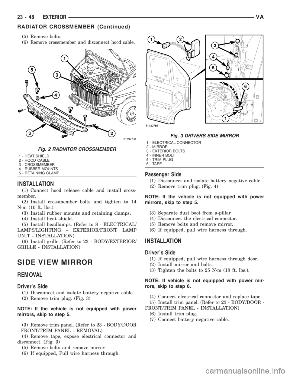
(5) Remove bolts.
(6)
Remove crossmember and disconnect hood cable.
INSTALLATION
(1) Connect hood release cable and install cross-
member.
(2) Install crossmember bolts and tighten to 14
N´m (10 ft. lbs.).
(3) Install rubber mounts and retaining clamps.
(4) Install heat shield.
(5) Install headlamps. (Refer to 8 - ELECTRICAL/
LAMPS/LIGHTING - EXTERIOR/FRONT LAMP
UNIT - INSTALLATION)
(6) Install grille. (Refer to 23 - BODY/EXTERIOR/
GRILLE - INSTALLATION)
SIDE VIEW MIRROR
REMOVAL
Driver's Side
(1) Disconnect and isolate battery negative cable.
(2) Remove trim plug. (Fig. 3)
NOTE: If the vehicle is not equipped with power
mirrors, skip to step 5.
(3) Remove trim panel. (Refer to 23 - BODY/DOOR
- FRONT/TRIM PANEL - REMOVAL)
(4) Remove tape, expose electrical connector and
disconnect. (Fig. 3)
(5) Remove bolts and remove mirror.
(6) If equipped, Pull wire harness through.
Passenger Side
(1) Disconnect and isolate battery negative cable.
(2) Remove trim plug. (Fig. 4)
NOTE: If the vehicle is not equipped with power
mirrors, skip to step 5.
(3) Separate dust boot from a-pillar.
(4) Disconnect the electrical connector.
(5) Remove bolts and remove mirror.
(6) If equipped, pull wire harness through.
INSTALLATION
Driver's Side
(1) If equipped, pull wire harness through door.
(2) Install mirror and bolts.
(3) Tighten the bolts to 25 N´m (18 ft. lbs.).
NOTE: If vehicle is not equipped with power mir-
rors, skip to step 6.
(4) Connect electrical connector and replace tape.
(5) Install trim panel. (Refer to 23 - BODY/DOOR -
FRONT/TRIM PANEL - INSTALLATION)
(6) Install trim plug.
(7) Connect battery negative cable.
Fig. 2 RADIATOR CROSSMEMBER
1 - HEAT SHIELD
2 - HOOD CABLE
3 - CROSSMEMBER
4 - RUBBER MOUNTS
5 - RETAINING CLAMP
Fig. 3 DRIVERS SIDE MIRROR
1 - ELECTRICAL CONNECTOR
2 - MIRROR
3 - EXTERIOR BOLTS
4 - INNER BOLT
5 - TRIM PLUG
6 - TAPE
23 - 48 EXTERIORVA
RADIATOR CROSSMEMBER (Continued)
Page 1108 of 1232
Cargo Van - Rear
(1) Remove the screws and retaining strips.
(2) Remove carpet/mat.
INSTALLATION
Cargo/Passenger Van - Front
(1) Position carpet/mat in vehicle.
(2) Install the jack storage cover.
(3) Install the cup holder. (Refer to 23 - BODY/IN-
STRUMENT PANEL/CUP HOLDER - INSTALLA-
TION)
(4) Install the tray behind the driver's seat and
install the three bolts.
(5) Install the stepwell scuff pads. (Refer to 23 -
BODY/INTERIOR/STEPWELL SCUFF PADS -
INSTALLATION)
Passenger Van - Rear
(1) Position carpet/mat in vehicle.
(2) Install the seat striker assemblies.
(3) Install the retaining strips and screws.
(4) Install the seats. (Refer to 23 - BODY/SEATS/
SEAT - INSTALLATION)
Cargo Van - Rear
(1) Position carpet/mat in vehicle.
(2) Install the retaining strips and screws.
COWL TRIM
REMOVAL
(1) Position door weatherstrip aside.
(2) Remove the jack storage cover, if necessary.
(3) Position aside carpet/mat, if necessary.
(4) Using a trim stick C-4755 or equivalent,
remove the cowl trim panel.
INSTALLATION
(1) Position the cowl trim panel and seat the clips
fully.
(2) Install the jack storage cover, if necessary.
(3) Position the carpet/mat back.
(4) Position the door weatherstrips back.
D-PILLAR TRIM
REMOVAL
(1) Remove the three plastic twist screws and
remove the panel.
INSTALLATION
(1) Install the panel and install the three twist
screws.
HEADLINER
REMOVAL
Cab Section
(1) Remove the a-pillar trim. (Refer to 23 - BODY/
INTERIOR/A-PILLAR TRIM - REMOVAL)
(2) Remove the sun visors. (Refer to 23 - BODY/
INTERIOR/SUN VISOR - REMOVAL)
(3) Remove the b-pillar trim. (Refer to 23 - BODY/
INTERIOR/B-PILLAR TRIM - REMOVAL)
(4) Remove the assist handle. (Refer to 23 - BODY/
INTERIOR/ASSIST HANDLE - REMOVAL)
(5) Remove the dome light. (Refer to 8 - ELECTRI-
CAL/LAMPS/LIGHTING - INTERIOR/CARGO
LAMP UNIT - REMOVAL)
(6) Carefully separate the headliner and remove.
Number 2 Section
(1) Disconnect and isolate battery negative cable.
(2) Remove the second and third row seats. (Refer
to 23 - BODY/SEATS/SEAT - REAR - REMOVAL)
NOTE: If vehicle is not equipped with rear air con-
ditioning unit, skip to step 8.
(3) Remove the push pin fasteners and remove the
rear air front duct cover.
(4) Disconnect the electrical connector at front of
cover.
(5) Remove the push pin fasteners and remove the
rear air middle duct cover.
(6) Disconnect the electrical connector.
(7) Remove the three push-pins and three screws
and remove the rear air cover.
(8) Remove the duct work.
(9) Release clips at front and rear of headliner and
remove.
Number 3 Section
(1) Disconnect and isolate battery negative cable.
(2) Remove the third and fourth row seats. (Refer
to 23 - BODY/SEATS/SEAT - REAR - REMOVAL)
NOTE: If vehicle is not equipped with rear air con-
ditioning unit, skip to step 8.
(3) Remove the push pin fasteners and remove the
rear air front duct cover.
(4) Disconnect the electrical connector at front of
cover.
(5) Remove the push pin fasteners and remove the
rear air middle duct cover.
(6) Disconnect the electrical connector.
(7) Remove the three push-pins and three screws
and remove the rear air cover.
(8) Remove the duct work.
23 - 70 INTERIORVA
CARPETS AND FLOOR MATS (Continued)
Page 1109 of 1232
(9) Release clips at front and rear of headliner and
remove.
Number 4 Section
(1) Disconnect and isolate battery negative cable.
(2) Remove the third and fourth row seats. (Refer
to 23 - BODY/SEATS/SEAT - REAR - REMOVAL)
NOTE: If vehicle is not equipped with rear air con-
ditioning unit, skip to step 8.
(3) Remove the push pin fasteners and remove the
rear air front duct cover.
(4) Disconnect the electrical connector at front of
cover.
(5) Remove the push pin fasteners and remove the
rear air middle duct cover.
(6) Disconnect the electrical connector.
(7) Remove the three push-pins and three screws
and remove the rear air cover.
(8) Remove the duct work.
(9) Release clips at front and rear of headliner and
remove.
INSTALLATION
Cab Section
(1) Position the headliner in vehicle and seat fully.
(2) Install dome light. (Refer to 8 - ELECTRICAL/
LAMPS/LIGHTING - INTERIOR/CARGO LAMP
UNIT - INSTALLATION)
(3) Install assist handle. (Refer to 23 - BODY/IN-
TERIOR/ASSIST HANDLE - INSTALLATION)
(4) Install b-pillar trim. (Refer to 23 - BODY/IN-
TERIOR/B-PILLAR TRIM - INSTALLATION)
(5) Install the sun visors. (Refer to 23 - BODY/IN-
TERIOR/SUN VISOR - INSTALLATION)
(6) Install the a-pillar trim. (Refer to 23 - BODY/
INTERIOR/A-PILLAR TRIM - INSTALLATION)
(7) Connect battery negative cable.
Number 2 Section
(1) Position the headliner in vehicle and seat fully.
NOTE: If vehicle is not equipped with rear air con-
ditioning unit, skip to step 8.
(2) Install rear air unit duct work.
(3) Install the rear air unit rear cover and install
the three screws and push-pins.
(4) Connect the electrical connector and install the
middle duct work cover.
(5) Install the push pin fasteners.
(6) Connect the electrical connector and install the
front duct work cover.
(7) Install the push pin fasteners.(8) Install the second and third row seats. (Refer
to 23 - BODY/SEATS/SEAT - INSTALLATION)
(9) Connect battery negative cable.
Number 3 Section
(1) Position the headliner in vehicle and seat fully.
NOTE: If vehicle is not equipped with rear air con-
ditioning unit, skip to step 8.
(2) Install rear air unit duct work.
(3) Install the rear air unit rear cover and install
the three screws and push-pins.
(4) Connect the electrical connector and install the
middle duct work cover.
(5) Install the push pin fasteners.
(6) Connect the electrical connector and install the
front duct work cover.
(7) Install the push pin fasteners.
(8) Install the third and fourth row seats. (Refer to
23 - BODY/SEATS/SEAT - INSTALLATION)
(9) Connect battery negative cable.
Number 4 Section
(1) Position the headliner in vehicle and seat fully.
NOTE: If vehicle is not equipped with rear air con-
ditioning unit, skip to step 8.
(2) Install rear air unit duct work.
(3) Install the rear air unit rear cover and install
the three screws and push-pins.
(4) Connect the electrical connector and install the
middle duct work cover.
(5) Install the push pin fasteners.
(6) Connect the electrical connector and install the
front duct work cover.
(7) Install the push pin fasteners.
(8) Install the third and fourth row seats. (Refer to
23 - BODY/SEATS/SEAT - INSTALLATION)
(9) Connect battery negative cable.
QUARTER TRIM PANEL
REMOVAL
Passenger Van
(1) Remove seats as necessary. (Refer to 23 -
BODY/SEATS/SEAT - REMOVAL)
(2) Remove d-pillar trim if necessary. (Refer to 23 -
BODY/INTERIOR/D-PILLAR TRIM - REMOVAL)
(3) Using a trim stick C-4755 or equivalent, sepa-
rate the push-pin fasteners and remove trim panels.
VAINTERIOR 23 - 71
HEADLINER (Continued)
Page 1112 of 1232
PAINT
TABLE OF CONTENTS
page page
PAINT
SPECIFICATIONS - PAINT CODES..........74
BASECOAT/CLEARCOAT FINISH
DESCRIPTION.........................74
PAINT TOUCH-UP
DESCRIPTION.........................74STANDARD PROCEDURE - PAINT TOUCH-UP . 75
FINESSE SANDING/BUFFING & POLISH
DESCRIPTION.........................75
PAINT
SPECIFICATIONS - PAINT CODES
EXTERIOR COLORS
EXTERIOR COLOR DAIMLERCHRYSLER
CODE
Steel Blue MB 5389
Brilliant Blue MB 5362
Orchid Green MB 6464
Flame Red MB 3534
Arctic White MB 9147
Black Blue MB 7103
Calcite Yellow MB 1234
Piedmont Red MB 3636
Hycanith Blue MB 5376
Black Gray MB 7103
Stone Gray MB 7160
Silver Gray MB 7708
BASECOAT/CLEARCOAT
FINISH
DESCRIPTION
The original equipment finish is a multi step pro-
cess that involves cleaning, applying electro de-posi-tion (E-coat), anti-chip primer, basecoat, and
clearcoat steps.
On most vehicles a two-part paint application
(basecoat/clearcoat) is used. Color paint that is
applied to primer is called basecoat. The clear coat
protects the basecoat from ultraviolet light and pro-
vides a durable high-gloss finish.
CAUTION: Do not use abrasive chemicals or com-
pounds on painted surfaces. Damage to finish can
result.
Do not use harsh alkaline based cleaning solvents
on painted surfaces. Damage to finish or color can
result.
PAINT TOUCH-UP
DESCRIPTION
When a painted metal surface has been scratched
or chipped, it should be touched-up as soon as possi-
ble to avoid corrosion. For best results, use MOPARt
Scratch Filler/Primer, Touch-Up Paints and Clear Top
Coat.
WARNING: USE AN OSHA APPROVED RESPIRATOR
AND SAFETY GLASSES WHEN SPRAYING PAINT
OR SOLVENTS IN A CONFINED AREA. PERSONAL
INJURY CAN RESULT.
23 - 74 PAINTVA
Page 1113 of 1232
STANDARD PROCEDURE - PAINT TOUCH-UP
(1) Scrape loose paint and corrosion from inside
scratch or chip.
(2) Clean affected area with MOPARtTar/Road
Oil Remover or equivalent, and allow to dry.
(3) Fill the inside of the scratch or chip with a coat
of filler/primer. Do not overlap primer onto good sur-
face finish. The applicator brush should be wet
enough to puddle-fill the scratch or chip without run-
ning. Do not stroke brush applicator on body surface.
Allow the filler/primer to dry hard.
(4) Cover the filler/primer with color touch-up
paint. Do not overlap touch-up color onto the original
color coat around the scratch or chip. Butt the new
color to the original color, if possible. Do not stroke
applicator brush on body surface. Allow touch-up
paint to dry hard.
(5) On vehicles without clearcoat, the touch-up
color can be lightly finesse sanded (1500 grit) and
polished with rubbing compound.
(6) On vehicles with clearcoat, apply clear top coat
to touch-up paint with the same technique as
described in Step 4. Allow clear top coat to dry hard.
If desired, Step 5 can be performed on clear top coat.
WARNING: AVOID PROLONGED SKIN CONTACT
WITH PETROLEUM OR ALCOHOL ± BASED CLEAN-ING SOLVENTS. PERSONAL INJURY CAN
RESULT.AVOID PROLONGED SKIN CONTACT WITH
PETROLEUM OR ALCOHOL ± BASED CLEANING
SOLVENTS. PERSONAL INJURY CAN RESULT.
FINESSE SANDING/BUFFING &
POLISH
DESCRIPTION
CAUTION: Do not remove more than .5 mils of
clearcoat finish, if equipped. Basecoat paint must
retain clearcoat for durability.
Use a Paint Thickness Gauge #PR-ETG-2X or equiv-
alent to determine film thickness before and after
the repair.
Minor acid etching, orange peel, or smudging in
clearcoat or single-stage finishes can be reduced with
light finesse sanding, hand buffing, and polishing.If
the finish has been finesse sanded in the past,
it cannot be repeated. Finesse sanding opera-
tion should be performed by a trained automo-
tive paint technician.
VAPAINT 23 - 75
PAINT TOUCH-UP (Continued)