2005 MERCEDES-BENZ SPRINTER light
[x] Cancel search: lightPage 1155 of 1232
SOLENOID VALVE
DESCRIPTION
The rear A/C solenoid valve is a two-position elec-
trically operated shut-off valve, which is used to con-
trol refrigerant flow to the rear A/C evaporator from
the A/C compressor. The solenoid valve is located in
the rear A/C evaporator housing and is attached by a
bracket.
OPERATION
The solenoid valve is used by the rear A/C control
module to control rear A/C output temperature and
to prevent evaporator freezing. Evaporator tempera-
ture is controlled by cycling the solenoid valve open
and closed, thereby controlling refrigerant flow to the
rear evaporator. The normally closed valve only
allows refrigerant to flow through it when power is
supplied to the solenoid by the rear A/C control mod-
ule.
DIAGNOSIS AND TESTING
For circuit descriptions and diagrams, refer to Air
Conditioning/Heater in Group 8W - Wiring Diagrams.
NOTE: Prior to performing the following checks,
verify that the front A/C system is operating prop-
erly.
(1) With the engine running, the front A/C switch
in the On position and the rear A/C blower switch in
the Off position, check that the rear evaporator is not
colder than the ambient temperature. If the evapora-
tor temperature is colder than the ambient tempera-
ture, the solenoid is allowing refrigerant to flow
through the rear evaporator when in the closed posi-
tion. If OK, go to Step 2. If not OK, replace the rear
A/C solenoid valve (Refer to 24 - HEATING & AIR
CONDITIONING/CONTROLS/SOLENOID - REMOV-
AL).
(2) With the ignition switch in the Off position and
the rear A/C solenoid valve wire harness discon-
nected, check for continuity between the two solenoid
valve terminals. If OK, go to Step 3. If not OK,
replace the solenoid valve (Refer to 24 - HEATING &
AIR CONDITIONING/CONTROLS/SOLENOID -
REMOVAL).
(3) With the ignition switch in the Off position and
the rear A/C solenoid valve wire harness discon-
nected, check the solenoid valve ground circuits for a
good ground at all times. If OK, go to Step 4. If not
OK, repair the open circuit to ground as required.(4) With the ignition switch and the front A/C
switch in the On position and the rear A/C solenoid
valve wire harness disconnected, check the harness
for battery power at terminal 2. If OK, replace the
solenoid valve (Refer to 24 - HEATING & AIR CON-
DITIONING/CONTROLS/SOLENOID - REMOVAL).
If not OK, test the A/C control module as required
(Refer to 24 - HEATING & AIR CONDITIONING/
CONTROLS/POWER MODULE - DIAGNOSIS AND
TESTING).
REMOVAL
(1) Recover the refrigerant from the refrigerant
system (Refer to 24 - HEATING & AIR CONDITION-
ING/PLUMBING - STANDARD PROCEDURE).
(2) Disconnect and isolate the battery negative
cable.
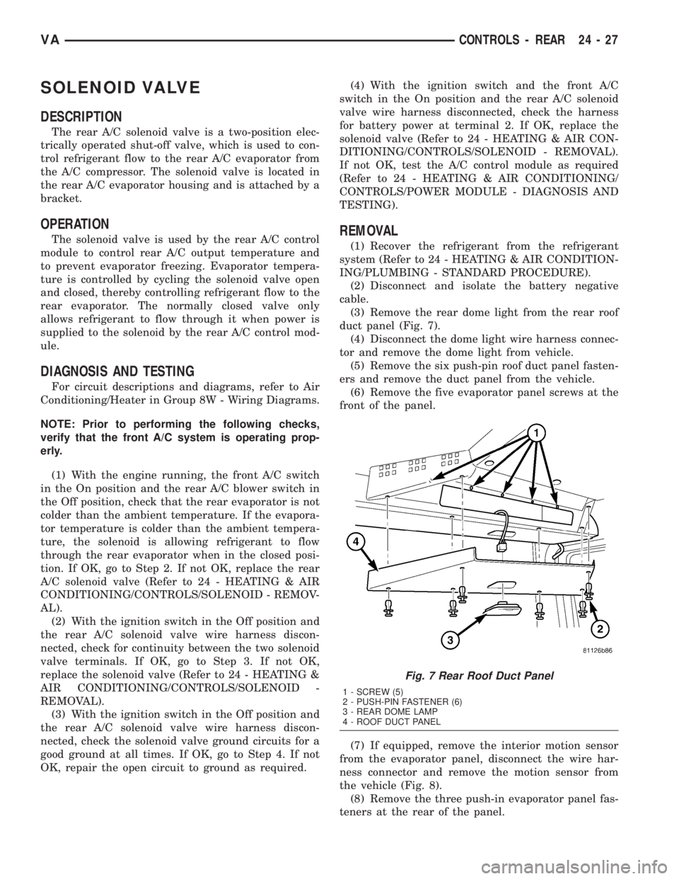
(3) Remove the rear dome light from the rear roof
duct panel (Fig. 7).
(4) Disconnect the dome light wire harness connec-
tor and remove the dome light from vehicle.
(5) Remove the six push-pin roof duct panel fasten-
ers and remove the duct panel from the vehicle.
(6) Remove the five evaporator panel screws at the
front of the panel.
(7) If equipped, remove the interior motion sensor
from the evaporator panel, disconnect the wire har-
ness connector and remove the motion sensor from
the vehicle (Fig. 8).
(8) Remove the three push-in evaporator panel fas-
teners at the rear of the panel.
Fig. 7 Rear Roof Duct Panel
1 - SCREW (5)
2 - PUSH-PIN FASTENER (6)
3 - REAR DOME LAMP
4 - ROOF DUCT PANEL
VACONTROLS - REAR 24 - 27
Page 1156 of 1232
(9) Remove the rear evaporator panel from the
vehicle.
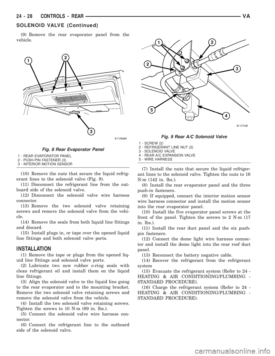
(10) Remove the nuts that secure the liquid refrig-
erant lines to the solenoid valve (Fig. 9).
(11) Disconnect the refrigerant line from the out-
board side of the solenoid valve.
(12) Disconnect the solenoid valve wire harness
connector.
(13) Remove the two solenoid valve retaining
screws and remove the solenoid valve from the vehi-
cle.
(14) Remove the seals from both liquid line fittings
and discard.
(15) Install plugs in, or tape over the opened liquid
line fittings and both solenoid valve ports.
INSTALLATION
(1) Remove the tape or plugs from the opened liq-
uid line fittings and solenoid valve ports.
(2) Lubricate two new rubber o-ring seals with
clean refrigerant oil and install them on the liquid
line fittings.
(3) Align the solenoid valve to the liquid line going
to the rear evaporator and to the mounting bracket.
Remove the two solenoid valve retaining screws and
remove the solenoid valve from the vehicle.
(4) Install the two solenoid valve retaining screws.
Tighten the screws to 10 N´m (89 in. lbs.).
(5) Connect the solenoid valve wire harness con-
nector.
(6) Connect the refrigerant line to the outboard
side of the solenoid valve.(7) Install the nuts that secure the liquid refriger-
ant lines to the solenoid valve. Tighten the nuts to 16
N´m (142 in. lbs.).
(8) Install the rear evaporator panel and the three
push-in fasteners.
(9) If equipped, connect the interior motion sensor
wire harness connector and install the motion sensor
into the rear evaporator panel.
(10) Install the five evaporator panel screws at the
front of the panel. Tighten the screws to 2 N´m (17
in. lbs.).
(11) Install the rear duct panel and the six push-
pin fasteners.
(12) Connect the dome light wire harness connec-
tor and install the dome light into the rear roof duct
panel.
(13) Reconnect the battery negative cable.
(14) Recover the refrigerant from the refrigerant
system
(15) Evacuate the refrigerant system (Refer to 24 -
HEATING & AIR CONDITIONING/PLUMBING -
STANDARD PROCEDURE).
(16) Charge the refrigerant system (Refer to 24 -
HEATING & AIR CONDITIONING/PLUMBING -
STANDARD PROCEDURE).
Fig. 8 Rear Evaporator Panel
1 - REAR EVAPORATOR PANEL
2 - PUSH-PIN FASTENER (3)
3 - INTERIOR MOTION SENSOR
Fig. 9 Rear A/C Solenoid Valve
1 - SCREW (2)
2 - REFRIGERANT LINE NUT (2)
3 - SOLENOID VALVE
4 - REAR A/C EXPANSION VALVE
5 - WIRE HARNESS
24 - 28 CONTROLS - REARVA
SOLENOID VALVE (Continued)
Page 1157 of 1232
TEMPERATURE CONTROL
DESCRIPTION
The optional rear heater-A/C unit output tempera-
ture is controlled by a thumbwheel-type control,
mounted in the switch panel on the instrument
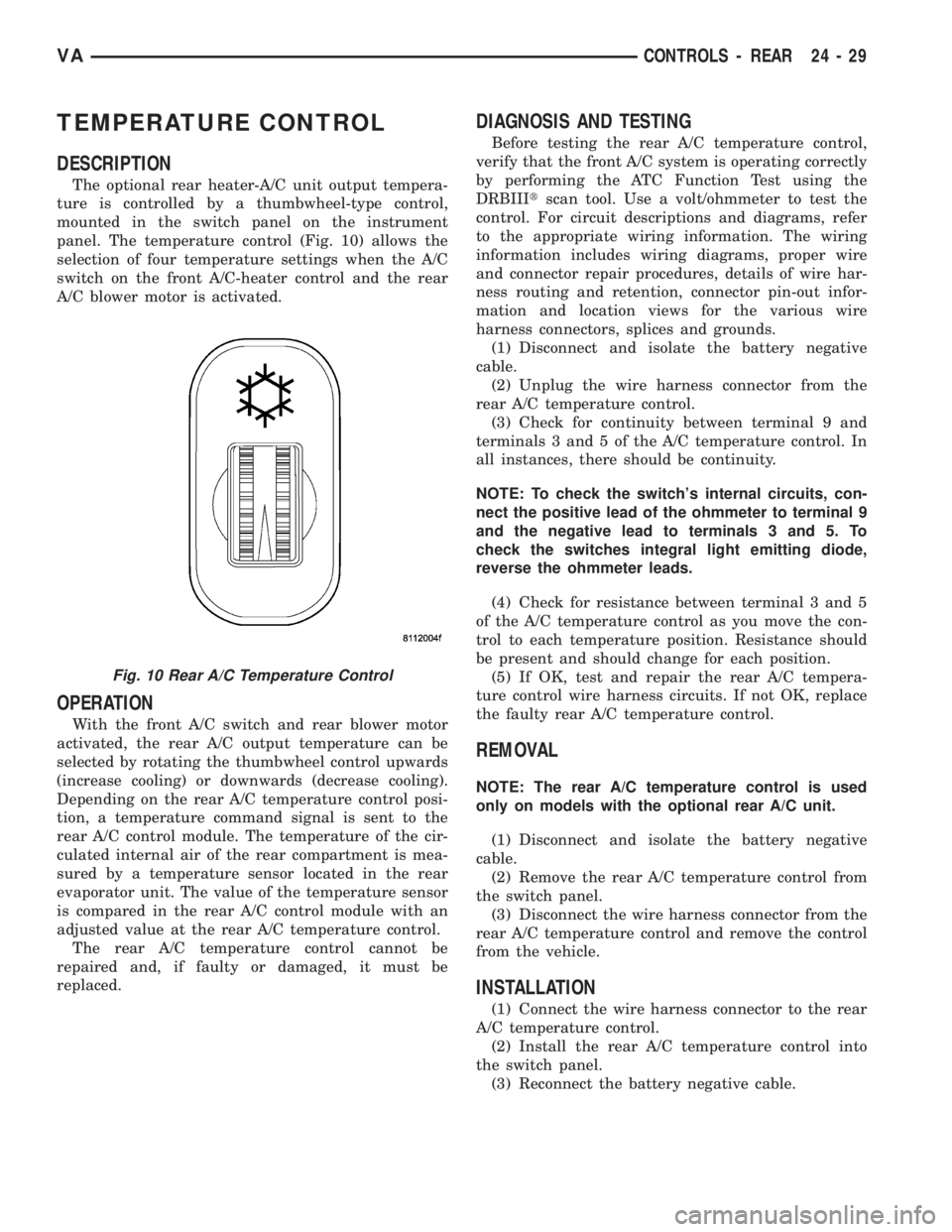
panel. The temperature control (Fig. 10) allows the
selection of four temperature settings when the A/C
switch on the front A/C-heater control and the rear
A/C blower motor is activated.
OPERATION
With the front A/C switch and rear blower motor
activated, the rear A/C output temperature can be
selected by rotating the thumbwheel control upwards
(increase cooling) or downwards (decrease cooling).
Depending on the rear A/C temperature control posi-
tion, a temperature command signal is sent to the
rear A/C control module. The temperature of the cir-
culated internal air of the rear compartment is mea-
sured by a temperature sensor located in the rear
evaporator unit. The value of the temperature sensor
is compared in the rear A/C control module with an
adjusted value at the rear A/C temperature control.
The rear A/C temperature control cannot be
repaired and, if faulty or damaged, it must be
replaced.
DIAGNOSIS AND TESTING
Before testing the rear A/C temperature control,
verify that the front A/C system is operating correctly
by performing the ATC Function Test using the
DRBIIItscan tool. Use a volt/ohmmeter to test the
control. For circuit descriptions and diagrams, refer
to the appropriate wiring information. The wiring
information includes wiring diagrams, proper wire
and connector repair procedures, details of wire har-
ness routing and retention, connector pin-out infor-
mation and location views for the various wire
harness connectors, splices and grounds.
(1) Disconnect and isolate the battery negative
cable.
(2) Unplug the wire harness connector from the
rear A/C temperature control.
(3) Check for continuity between terminal 9 and
terminals 3 and 5 of the A/C temperature control. In
all instances, there should be continuity.
NOTE: To check the switch's internal circuits, con-
nect the positive lead of the ohmmeter to terminal 9
and the negative lead to terminals 3 and 5. To
check the switches integral light emitting diode,
reverse the ohmmeter leads.
(4) Check for resistance between terminal 3 and 5
of the A/C temperature control as you move the con-
trol to each temperature position. Resistance should
be present and should change for each position.
(5) If OK, test and repair the rear A/C tempera-
ture control wire harness circuits. If not OK, replace
the faulty rear A/C temperature control.
REMOVAL
NOTE: The rear A/C temperature control is used
only on models with the optional rear A/C unit.
(1) Disconnect and isolate the battery negative
cable.
(2) Remove the rear A/C temperature control from
the switch panel.
(3) Disconnect the wire harness connector from the
rear A/C temperature control and remove the control
from the vehicle.
INSTALLATION
(1) Connect the wire harness connector to the rear
A/C temperature control.
(2) Install the rear A/C temperature control into
the switch panel.
(3) Reconnect the battery negative cable.
Fig. 10 Rear A/C Temperature Control
VACONTROLS - REAR 24 - 29
Page 1158 of 1232
TEMPERATURE SENSOR
DESCRIPTION
The rear A/C air temperature sensor is located in
the rear evaporator housing. The rear temperature
sensor provides an air outlet temperature signal to
the rear A/C control module through a two-wire har-
ness lead and connector.
The temperature sensor cannot be adjusted or
repaired and, if faulty or damaged, it must be
replaced.
OPERATION
The rear A/C temperature sensor is a variable
resistor that operates on a five-volt reference signal
sent to it by the rear A/C control module. The resis-
tance in the sensor changes as air temperature
changes. Based upon the resistance in the sensor, a
specific voltage on the temperature sensor signal cir-
cuit is returned to the rear control module, which is
programmed to correspond to a specific temperature.
DIAGNOSIS AND TESTING
Before testing the rear air temperature sensor, ver-
ify that the front A/C system is operating correctly by
performing the ATC Function Test using the DRBIIIt
scan tool. For circuit descriptions and diagrams, refer
to the appropriate wiring information. The wiring
information includes wiring diagrams, proper wire
and connector repair procedures, details of wire har-
ness routing and retention, connector pin-out infor-
mation and location views for the various wire
harness connectors, splices and grounds.
(1) Disconnect and isolate the battery negative
cable.
(2) Unplug the wire harness connector for the rear
air temperature sensor.
(3) Measure the resistance of the temperature sen-
sor. At ±40É C (±40É F), the sensor resistance is 336
kilohms. At 55É C (131É F), the sensor resistance is
25 kilohms. The sensor resistance should read
between these two values.
(4) If OK, test and repair the rear air temperature
sensor wire harness circuits. If not OK, replace the
faulty air temperature sensor.
REMOVAL
(1) Disconnect and isolate the battery negative
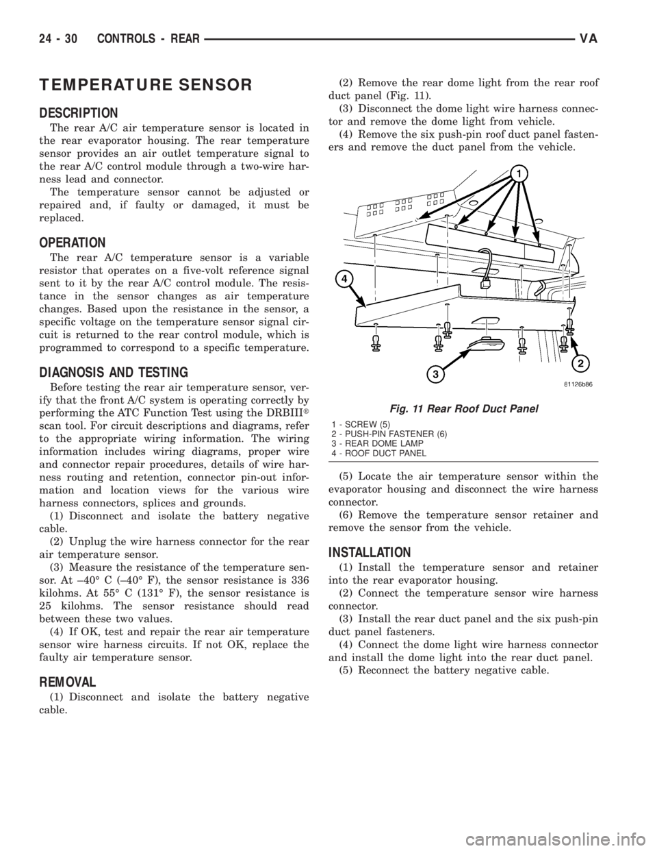
cable.(2) Remove the rear dome light from the rear roof
duct panel (Fig. 11).
(3) Disconnect the dome light wire harness connec-
tor and remove the dome light from vehicle.
(4) Remove the six push-pin roof duct panel fasten-
ers and remove the duct panel from the vehicle.
(5) Locate the air temperature sensor within the
evaporator housing and disconnect the wire harness
connector.
(6) Remove the temperature sensor retainer and
remove the sensor from the vehicle.
INSTALLATION
(1) Install the temperature sensor and retainer
into the rear evaporator housing.
(2) Connect the temperature sensor wire harness
connector.
(3) Install the rear duct panel and the six push-pin
duct panel fasteners.
(4) Connect the dome light wire harness connector
and install the dome light into the rear duct panel.
(5) Reconnect the battery negative cable.
Fig. 11 Rear Roof Duct Panel
1 - SCREW (5)
2 - PUSH-PIN FASTENER (6)
3 - REAR DOME LAMP
4 - ROOF DUCT PANEL
24 - 30 CONTROLS - REARVA
Page 1167 of 1232
DISTRIBUTION - REAR
TABLE OF CONTENTS
page page
AIR FILTER
REMOVAL.............................39
INSTALLATION.........................39
BLOWER MOTOR
REMOVAL.............................39INSTALLATION.........................40
REAR A/C HOUSING
REMOVAL.............................40
INSTALLATION.........................41
AIR FILTER
REMOVAL
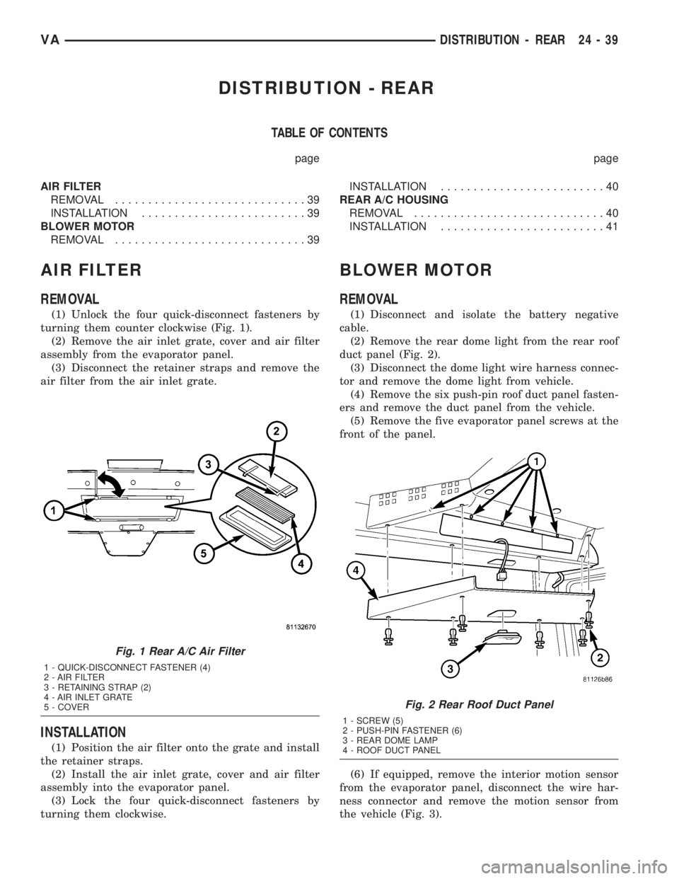
(1) Unlock the four quick-disconnect fasteners by
turning them counter clockwise (Fig. 1).
(2) Remove the air inlet grate, cover and air filter
assembly from the evaporator panel.
(3) Disconnect the retainer straps and remove the
air filter from the air inlet grate.
INSTALLATION
(1) Position the air filter onto the grate and install
the retainer straps.
(2) Install the air inlet grate, cover and air filter
assembly into the evaporator panel.
(3) Lock the four quick-disconnect fasteners by
turning them clockwise.
BLOWER MOTOR
REMOVAL
(1) Disconnect and isolate the battery negative
cable.
(2) Remove the rear dome light from the rear roof
duct panel (Fig. 2).
(3) Disconnect the dome light wire harness connec-
tor and remove the dome light from vehicle.
(4) Remove the six push-pin roof duct panel fasten-
ers and remove the duct panel from the vehicle.
(5) Remove the five evaporator panel screws at the
front of the panel.
(6) If equipped, remove the interior motion sensor
from the evaporator panel, disconnect the wire har-
ness connector and remove the motion sensor from
the vehicle (Fig. 3).
Fig. 1 Rear A/C Air Filter
1 - QUICK-DISCONNECT FASTENER (4)
2 - AIR FILTER
3 - RETAINING STRAP (2)
4 - AIR INLET GRATE
5 - COVER
Fig. 2 Rear Roof Duct Panel
1 - SCREW (5)
2 - PUSH-PIN FASTENER (6)
3 - REAR DOME LAMP
4 - ROOF DUCT PANEL
VADISTRIBUTION - REAR 24 - 39
Page 1168 of 1232
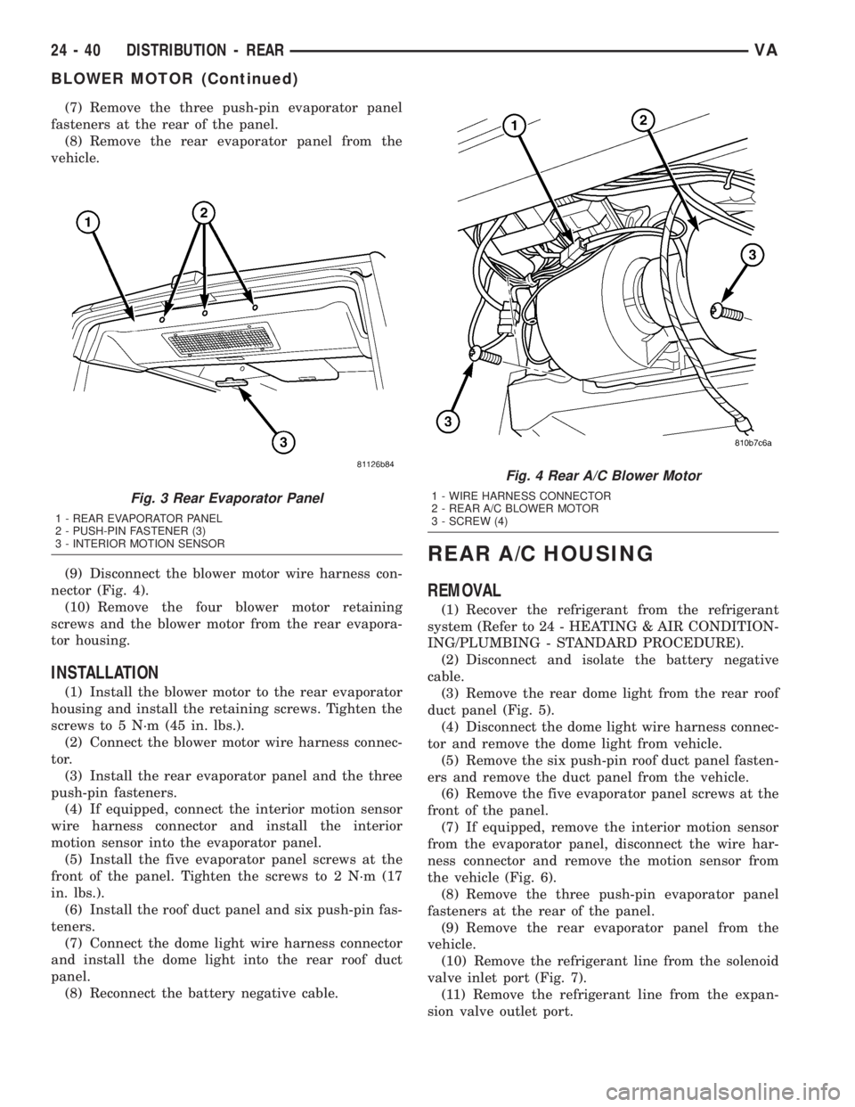
(7) Remove the three push-pin evaporator panel
fasteners at the rear of the panel.
(8) Remove the rear evaporator panel from the
vehicle.
(9) Disconnect the blower motor wire harness con-
nector (Fig. 4).
(10) Remove the four blower motor retaining
screws and the blower motor from the rear evapora-
tor housing.
INSTALLATION
(1) Install the blower motor to the rear evaporator
housing and install the retaining screws. Tighten the
screws to 5 N´m (45 in. lbs.).
(2) Connect the blower motor wire harness connec-
tor.
(3) Install the rear evaporator panel and the three
push-pin fasteners.
(4) If equipped, connect the interior motion sensor
wire harness connector and install the interior
motion sensor into the evaporator panel.
(5) Install the five evaporator panel screws at the
front of the panel. Tighten the screws to 2 N´m (17
in. lbs.).
(6) Install the roof duct panel and six push-pin fas-
teners.
(7) Connect the dome light wire harness connector
and install the dome light into the rear roof duct
panel.
(8) Reconnect the battery negative cable.
REAR A/C HOUSING
REMOVAL
(1) Recover the refrigerant from the refrigerant
system (Refer to 24 - HEATING & AIR CONDITION-
ING/PLUMBING - STANDARD PROCEDURE).
(2) Disconnect and isolate the battery negative
cable.
(3) Remove the rear dome light from the rear roof
duct panel (Fig. 5).
(4) Disconnect the dome light wire harness connec-
tor and remove the dome light from vehicle.
(5) Remove the six push-pin roof duct panel fasten-
ers and remove the duct panel from the vehicle.
(6) Remove the five evaporator panel screws at the
front of the panel.
(7) If equipped, remove the interior motion sensor
from the evaporator panel, disconnect the wire har-
ness connector and remove the motion sensor from
the vehicle (Fig. 6).
(8) Remove the three push-pin evaporator panel
fasteners at the rear of the panel.
(9) Remove the rear evaporator panel from the
vehicle.
(10) Remove the refrigerant line from the solenoid
valve inlet port (Fig. 7).
(11) Remove the refrigerant line from the expan-
sion valve outlet port.
Fig. 3 Rear Evaporator Panel
1 - REAR EVAPORATOR PANEL
2 - PUSH-PIN FASTENER (3)
3 - INTERIOR MOTION SENSOR
Fig. 4 Rear A/C Blower Motor
1 - WIRE HARNESS CONNECTOR
2 - REAR A/C BLOWER MOTOR
3 - SCREW (4)
24 - 40 DISTRIBUTION - REARVA
BLOWER MOTOR (Continued)
Page 1170 of 1232
(6) Install the suctiont line to the expansion valve
outlet port. Tighten the retainer to 10 N´m (89 in.
lbs.).
(7) Install the refrigerant line to the solenoid valve
inlet port. Tighten the retainer to 16 N´m (142 in.
lbs.).
(8) Install the rear evaporator panel and the three
push-pin fasteners.
(9) If equipped, connect the interior motion sensor
wire harness connector and install the interior
motion sensor into the evaporator panel.
(10) Install the five evaporator panel screws at the
front of the panel. Tighten the screws to 2 N´m (17
in. lbs.).
(11) Install the roof duct panel and six push-pin
fasteners.
(12) Connect the dome light wire harness connec-
tor and install the dome light into the rear roof duct
panel.
(13) Reconnect the battery negative cable.
(14) Evacuate the refrigerant system (Refer to 24 -
HEATING & AIR CONDITIONING/PLUMBING -
STANDARD PROCEDURE).
(15) Charge the refrigerant system (Refer to 24 -
HEATING & AIR CONDITIONING/PLUMBING -
STANDARD PROCEDURE).
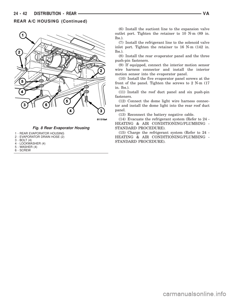
Fig. 8 Rear Evaporator Housing
1 - REAR EVAPORATOR HOUSING
2 - EVAPORATOR DRAIN HOSE (2)
3 - BOLT (4)
4 - LOCKWASHER (4)
5 - WASHER (4)
6 - SCREW
24 - 42 DISTRIBUTION - REARVA
REAR A/C HOUSING (Continued)
Page 1172 of 1232
PLUMBING
DESCRIPTION - REFRIGERANT LINE
The refrigerant lines and hoses are used to carry
the refrigerant between the various air conditioning
system components. A barrier hose design with a
nylon tube, which is sandwiched between rubber lay-
ers, is used for the R-134a air conditioning system on
this vehicle. This nylon tube helps to further contain
the R-134a refrigerant, which has a smaller molecu-
lar structure than R-12 refrigerant. The ends of the
refrigerant hoses are made from lightweight alumi-
num or steel, and commonly use braze-less fittings.
Any kinks or sharp bends in the refrigerant plumb-
ing will reduce the capacity of the entire air condi-
tioning system. Kinks and sharp bends reduce the
flow of refrigerant in the system. A good rule for the
flexible hose refrigerant lines is to keep the radius of
all bends at least ten times the diameter of the hose.
In addition, the flexible hose refrigerant lines should
be routed so they are at least 80 millimeters (3
inches) from the exhaust manifold.
OPERATION - REFRIGERANT LINE
High pressures are produced in the refrigerant sys-
tem when the air conditioning compressor is operat-
ing. Extreme care must be exercised to make sure
that each of the refrigerant system connections is
pressure-tight and leak free. It is a good practice to
inspect all flexible hose refrigerant lines at least once
a year to make sure they are in good condition and
properly routed.
The refrigerant lines and hoses cannot be repaired
and, if faulty or damaged, they must be replaced.
WARNING
WARNING: THE AIR CONDITIONING SYSTEM CON-
TAINS REFRIGERANT UNDER HIGH PRESSURE.
SEVERE PERSONAL INJURY MAY RESULT FROM
IMPROPER SERVICE PROCEDURES. REPAIRS
SHOULD ONLY BE PERFORMED BY QUALIFIED
SERVICE PERSONNEL.AVOID BREATHING THE REFRIGERANT AND
REFRIGERANT OIL VAPOR OR MIST. EXPOSURE
MAY IRRITATE THE EYES, NOSE, AND/OR THROAT.
WEAR EYE PROTECTION WHEN SERVICING THE
AIR CONDITIONING REFRIGERANT SYSTEM. SERI-
OUS EYE INJURY CAN RESULT FROM DIRECT
CONTACT WITH THE REFRIGERANT. IF EYE CON-
TACT OCCURS, SEEK MEDICAL ATTENTION IMME-
DIATELY.
DO NOT EXPOSE THE REFRIGERANT TO OPEN
FLAME. POISONOUS GAS IS CREATED WHEN
REFRIGERANT IS BURNED. AN ELECTRONIC LEAK
DETECTOR IS RECOMMENDED.
IF ACCIDENTAL SYSTEM DISCHARGE OCCURS,
VENTILATE THE WORK AREA BEFORE RESUMING
SERVICE. LARGE AMOUNTS OF REFRIGERANT
RELEASED IN A CLOSED WORK AREA WILL DIS-
PLACE THE OXYGEN AND CAUSE SUFFOCATION.
THE EVAPORATION RATE OF R-134a REFRIGER-
ANT AT AVERAGE TEMPERATURE AND ALTITUDE
IS EXTREMELY HIGH. AS A RESULT, ANYTHING
THAT COMES IN CONTACT WITH THE REFRIGER-
ANT WILL FREEZE. ALWAYS PROTECT THE SKIN
OR DELICATE OBJECTS FROM DIRECT CONTACT
WITH THE REFRIGERANT.
THE R-134a SERVICE EQUIPMENT OR THE VEHI-
CLE REFRIGERANT SYSTEM SHOULD NOT BE
PRESSURE TESTED OR LEAK TESTED WITH COM-
PRESSED AIR. SOME MIXTURES OF AIR AND
R-134a HAVE BEEN SHOWN TO BE COMBUSTIBLE
AT ELEVATED PRESSURES. THESE MIXTURES ARE
POTENTIALLY DANGEROUS, AND MAY RESULT IN
FIRE OR EXPLOSION CAUSING INJURY OR PROP-
ERTY DAMAGE.
24 - 44 PLUMBINGVA