2005 MERCEDES-BENZ SPRINTER light
[x] Cancel search: lightPage 277 of 1232
VEHICLE THEFT SECURITY
TABLE OF CONTENTS
page page
VEHICLE THEFT SECURITY
DESCRIPTION..........................1
OPERATION............................1
DIAGNOSIS AND TESTING - VEHICLE THEFT
SECURITY............................1
INTRUSION SENSOR
REMOVAL.............................2
INSTALLATION..........................2
SECURITY SYSTEM MODULE
REMOVAL.............................2
INSTALLATION..........................2SENTRY KEY REMOTE ENTRY MODULE
DESCRIPTION..........................2
OPERATION............................3
REMOVAL.............................3
INSTALLATION..........................4
SIREN
REMOVAL.............................4
INSTALLATION..........................4
TRANSPONDER KEY
DESCRIPTION..........................5
OPERATION............................5
VEHICLE THEFT SECURITY
DESCRIPTION
An anti-theft alarm with battery powered horn is
available as an option and includes interior monitor-
ing, anti-tow away protection and rear window mon-
itoring based on the heater wires. The alarm is
automatically activated when the central locking sys-
tem is operated.
The alarm will sound when any of the following
occur:
²A door is opened
²A door is unlocked from inside the vehicle
²The hood is opened
²The vehicle is raised at the front or rear
²The trailer wire harness is disconnected
²Movements inside the vehicle
²The central locking is unlocked by a key at any
other door than the driver's door
The alarm is functional about 30 seconds after the
vehicle is locked using the RKE transmitter or the
key in the driver's door. Activation is indicated by the
indicator lights flashing three times and the warning
lamp flashing in the switch. If persons or animals
remain in the locked vehicle, the operator should
switch off the interior monitor to avoid a false alarm.
OPERATION
The anti-theft alarm is activated/deactivated by
locking/unlocking the vehicle with the remote trans-
mitter or with the key at the driver's door. The key
must be held in the locking position for more than
two seconds. Activation is indicated by the turn sig-
nal lights flashing once. Unlocking the vehicle at one
of the other doors will trigger an alarm.The interior monitoring system included in the
anti-theft alarm is based on ultrasonics and triggers
an alarm if an object intrudes the interior of the
vehicle or if any movement is detected inside the
vehicle. For proper and effective protection, all win-
dows and the sunroof must be closed.
To switch off the interior monitoring system and /
or the anti-tow away protection, a switch with LED
indicator light is provided in the switch panel. An
alarm button enables the operator to trigger an
alarm manually and to lock all doors if they are
closed. Triggering an alarm makes the horn sound
and the turn signals flash until the alarm is switched
off.
The anti-theft alarm control unit includes a gradi-
ent indicator as anti-tow away protection. The gradi-
ent indicator triggers an audible and visual alarm if
the vehicle is lifted (to tow away or to remove the
wheels). The alarm remains effective even if the bat-
tery is disconnected as the horn is powered by its
own battery. The interior monitoring system should
be switched off if people and/or animals are left in
the vehicle.
DIAGNOSIS AND TESTING - VEHICLE THEFT
SECURITY
Any diagnosis of the Vehicle Theft Security
system should begin with the use of the DRB
IIItdiagnostic tool. For information on the use
of the DRB IIIt, refer to the appropriate Diag-
nostic Service Manual.
VAVEHICLE THEFT SECURITY 8Q - 1
Page 281 of 1232
TRANSPONDER KEY
DESCRIPTION
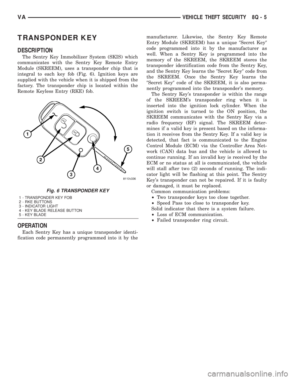
The Sentry Key Immobilizer System (SKIS) which
communicates with the Sentry Key Remote Entry
Module (SKREEM), uses a transponder chip that is
integral to each key fob (Fig. 6). Ignition keys are
supplied with the vehicle when it is shipped from the
factory. The transponder chip is located within the
Remote Keyless Entry (RKE) fob.
OPERATION
Each Sentry Key has a unique transponder identi-
fication code permanently programmed into it by themanufacturer. Likewise, the Sentry Key Remote
Entry Module (SKREEM) has a unique9Secret Key9
code programmed into it by the manufacturer as
well. When a Sentry Key is programmed into the
memory of the SKREEM, the SKREEM stores the
transponder identification code from the Sentry Key,
and the Sentry Key learns the9Secret Key9code from
the SKREEM. Once the Sentry Key learns the
9Secret Key9code of the SKREEM, it is also perma-
nently programmed into the transponder's memory.
The Sentry Key's transponder is within the range
of the SKREEM's transponder ring when it is
inserted into the ignition lock cylinder. When the
ignition switch is turned to the ON position, the
SKREEM communicates with the Sentry Key via a
radio frequency (RF) signal. The SKREEM deter-
mines if a valid key is present based on the informa-
tion it receives from the Sentry Key. If a valid key is
detected, that fact is communicated to the Engine
Control Module (ECM) via the Controller Area Net-
work (CAN) data bus and the vehicle is allowed to
continue running. If an invalid key is received by the
ECM or no status at all is communicated, the vehicle
will stall after two (2) seconds of running. The indi-
cator light will be flashing at this point. The Sentry
Key's transponder can not be repaired. If it is faulty
or damaged, it must be replaced.
Common communication problems:
²Two transponder keys too close together.
²Speed Pass too close to transponder key.
Solid indicator that there is a system failure.
²Loss of ECM communication.
²Failed transponder ring circuit.
Fig. 6 TRANSPONDER KEY
1 - TRANSPONDER KEY FOB
2 - RKE BUTTONS
3 - INDICATOR LIGHT
4 - KEY BLADE RELEASE BUTTON
5 - KEY BLADE
VAVEHICLE THEFT SECURITY 8Q - 5
Page 283 of 1232
WIPERS/WASHERS
TABLE OF CONTENTS
page page
WIPERS/WASHERS
DESCRIPTION..........................1
OPERATION............................3
DIAGNOSIS AND TESTING - WIPER &
WASHER SYSTEM.....................5
CLEANING - WIPER & WASHER SYSTEM.....5
INSPECTION - WIPER & WASHER SYSTEM . . . 6
CHECK VALVE
DESCRIPTION..........................7
OPERATION............................7
REMOVAL.............................7
INSTALLATION..........................7
WASHER FLUID LEVEL SWITCH
DESCRIPTION..........................7
OPERATION............................8
WASHER HOSES/TUBES
DESCRIPTION..........................8
OPERATION............................9
WASHER NOZZLE
DESCRIPTION..........................9
OPERATION............................9
REMOVAL.............................9
INSTALLATION..........................9
WASHER PUMP/MOTOR
DESCRIPTION..........................9
OPERATION...........................10
REMOVAL.............................10
INSTALLATION.........................10
WASHER RESERVOIR
DESCRIPTION.........................11OPERATION...........................11
REMOVAL.............................11
INSTALLATION.........................12
WIPER ARM
DESCRIPTION.........................13
OPERATION...........................14
REMOVAL.............................14
INSTALLATION.........................14
WIPER BLADE
DESCRIPTION.........................15
OPERATION...........................15
REMOVAL.............................16
INSTALLATION.........................16
WIPER LINKAGE
DESCRIPTION.........................17
OPERATION...........................17
REMOVAL.............................17
INSTALLATION.........................18
WIPER MOTOR
DESCRIPTION.........................19
OPERATION...........................19
REMOVAL.............................19
INSTALLATION.........................19
WIPER RELAY
DESCRIPTION.........................20
OPERATION...........................21
REMOVAL.............................22
INSTALLATION.........................22
WIPERS/WASHERS
DESCRIPTION
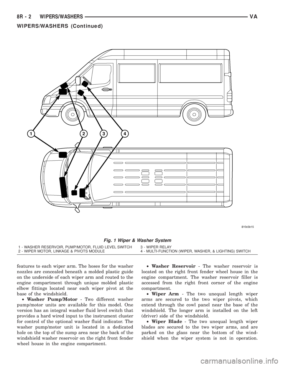
An electrically operated intermittent wiper and
washer system is standard factory-installed safety
equipment on this model (Fig. 1). The wiper and
washer system includes the following major compo-
nents, which are described in further detail else-
where in this service information:
²Check Valve- The washer system check valve
is integral to the plumbing fitting located in the
washer plumbing between the cowl plenum washer
hose and the two washer nozzle hoses, and is located
beneath the cowl top panel at the base of the wind-
shield in the engine compartment.
²Multi-Function Switch- The multi-function
switch is secured to the top of the steering column,just below the steering wheel. Only the left (lighting),
right (wiper) control stalks and the hazard warning
switch button for the multi-function switch are visi-
ble, the remainder of the switch is concealed beneath
the steering column shrouds. The multi-function
switch contains all of the switches for both the wiper
and washer systems.(Refer to 8 - ELECTRICAL/
LAMPS/LIGHTING - EXTERIOR/MULTI-FUNC-
TION SWITCH - DESCRIPTION)
²Washer Fluid Level Switch- The optional
washer fluid level switch is integral to a unique ver-
sion of the washer pump/motor unit, which is located
in a dedicated hole on the top of the sump area near
the back of the windshield washer reservoir on the
right front fender wheel house in the engine com-
partment.
²Washer Nozzle- A single washer nozzle with
three separate orifices is secured with integral snap
VAWIPERS/WASHERS 8R - 1
Page 284 of 1232
features to each wiper arm. The hoses for the washer
nozzles are concealed beneath a molded plastic guide
on the underside of each wiper arm and routed to the
engine compartment through unique molded plastic
elbow fittings located near each wiper pivot at the
base of the windshield.
²Washer Pump/Motor- Two different washer
pump/motor units are available for this model. One
version has an integral washer fluid level switch that
provides a hard wired input to the instrument cluster
for control of the optional washer fluid indicator. The
washer pump/motor unit is located in a dedicated
hole on the top of the sump area near the back of the
windshield washer reservoir on the right front fender
wheel house in the engine compartment.²Washer Reservoir- The washer reservoir is
located on the right front fender wheel house in the
engine compartment. The washer reservoir filler is
accessed from the right front corner of the engine
compartment.
²Wiper Arm- The two unequal length wiper
arms are secured to the two wiper pivots, which
extend through the cowl panel near the base of the
windshield. The longer arm is installed on the left
(driver) side of the windshield.
²Wiper Blade- The two unequal length wiper
blades are secured to the two wiper arms, and are
parked on the glass near the bottom of the wind-
shield when the wiper system is not in operation.
Fig. 1 Wiper & Washer System
1 - WASHER RESERVOIR, PUMP/MOTOR, FLUID LEVEL SWITCH 3 - WIPER RELAY
2 - WIPER MOTOR, LINKAGE & PIVOTS MODULE 4 - MULTI-FUNCTION (WIPER, WASHER, & LIGHTING) SWITCH
8R - 2 WIPERS/WASHERSVA
WIPERS/WASHERS (Continued)
Page 287 of 1232
and methods. Proper testing of the intermittent wipe
logic circuitry within the fuse block requires the use
of a DRBIIItscan tool. Refer to the appropriate diag-
nostic information. Refer to the owner's manual in
the vehicle glove box for more information on the fea-
tures and operation of the wiper and washer system.
DIAGNOSIS AND TESTING - WIPER &
WASHER SYSTEM
If the wiper motor operates, but the wipers do not
move on the windshield, replace the faulty wiper
linkage module. If the washer pump/motor operates,
but no washer fluid is dispensed on the glass; or, if
the wipers operate, but chatter, lift, or do not clear
the glass, clean and inspect the wiper and washer
system components as required. (Refer to 8 - ELEC-
TRICAL/WIPERS/WASHERS - CLEANING) and
(Refer to 8 - ELECTRICAL/WIPERS/WASHERS -
INSPECTION). For diagnosis and testing of the
multi-function switch (Refer to 8 - ELECTRICAL/
LAMPS/LIGHTING - EXTERIOR/MULTI-FUNC-
TION SWITCH - DIAGNOSIS AND TESTING).
Refer to the appropriate wiring information. The wir-
ing information includes wiring diagrams, proper
wire and connector repair procedures, details of wire
harness routing and retention, connector pin-out
information and location views for the various wire
harness connectors, splices and grounds.
The hard wired circuits and components of the
wiper and washer system may be diagnosed and
tested using conventional diagnostic tools and proce-
dures. However, conventional diagnostic methods
may not prove conclusive in the diagnosis of the
intermittent wipe logic circuitry contained within the
fuse block underneath the steering column. The most
reliable, efficient, and accurate means to diagnose
the intermittent wipe logic circuitry requires the use
of a DRBIIItscan tool. Refer to the appropriate diag-
nostic information.
WARNING: ON VEHICLES EQUIPPED WITH AIR-
BAGS, DISABLE THE SUPPLEMENTAL RESTRAINT
SYSTEM BEFORE ATTEMPTING ANY STEERING
WHEEL, STEERING COLUMN, DRIVER AIRBAG,
PASSENGER AIRBAG, SEAT BELT TENSIONER, OR
INSTRUMENT PANEL COMPONENT DIAGNOSIS OR
SERVICE. DISCONNECT AND ISOLATE THE BAT-
TERY NEGATIVE (GROUND) CABLE, THEN WAIT
TWO MINUTES FOR THE SYSTEM CAPACITOR TO
DISCHARGE BEFORE PERFORMING FURTHER
DIAGNOSIS OR SERVICE. THIS IS THE ONLY SURE
WAY TO DISABLE THE SUPPLEMENTAL
RESTRAINT SYSTEM. FAILURE TO TAKE THE
PROPER PRECAUTIONS COULD RESULT IN ACCI-
DENTAL AIRBAG DEPLOYMENT AND POSSIBLE
PERSONAL INJURY.
CLEANING - WIPER & WASHER SYSTEM
WIPER SYSTEM
The squeegees of wiper blades exposed to the ele-
ments for a long time tend to lose their wiping effec-
tiveness. Periodic cleaning of the squeegees is
suggested to remove any deposits of salt or road film.
The wiper blades, arms, and windshield glass should
only be cleaned using a sponge or soft cloth and
windshield washer fluid, a mild detergent, or a non-
abrasive cleaner. If the wiper blades continue to
leave streaks, smears, hazing, or beading on the
glass after thorough cleaning of the squeegees and
the glass, the entire wiper blade assembly must be
replaced.
CAUTION: Protect the rubber squeegees of the
wiper blades from any petroleum-based cleaners,
solvents, or contaminants. These products can rap-
idly deteriorate the rubber squeegees.
WASHER SYSTEM
If the washer system is contaminated with foreign
material, drain the washer reservoir by removing the
washer pump/motor from the reservoir. Clean foreign
material from the inside of the washer pump/motor
inlet nipple and the washer reservoir using clean
washer fluid, a mild detergent, or a non-abrasive
cleaner. Flush foreign material from the washer sys-
tem plumbing by first disconnecting the washer
hoses from the washer nozzles, then running the
washer pump/motor to run clean washer fluid or
water through the system. Plugged or restricted
washer nozzles should be carefully back-flushed
using compressed air. If the washer nozzle obstruc-
tion cannot be cleared, replace the washer nozzle.
CAUTION: Never introduce petroleum-based clean-
ers, solvents, or contaminants into the washer sys-
tem. These products can rapidly deteriorate the
rubber seals and hoses of the washer system, as
well as the rubber squeegees of the wiper blades.
CAUTION: Never use compressed air to flush the
washer system plumbing. Compressed air pres-
sures are too great for the washer system plumbing
components and will result in further system dam-
age. Never use sharp instruments to clear a
plugged washer nozzle or damage to the nozzle ori-
fice and improper nozzle spray patterns will result.
VAWIPERS/WASHERS 8R - 5
WIPERS/WASHERS (Continued)
Page 292 of 1232
and the grommet seal, which is a light press fit. An
integral electrical connector receptacle is located on
the top of the motor housing.
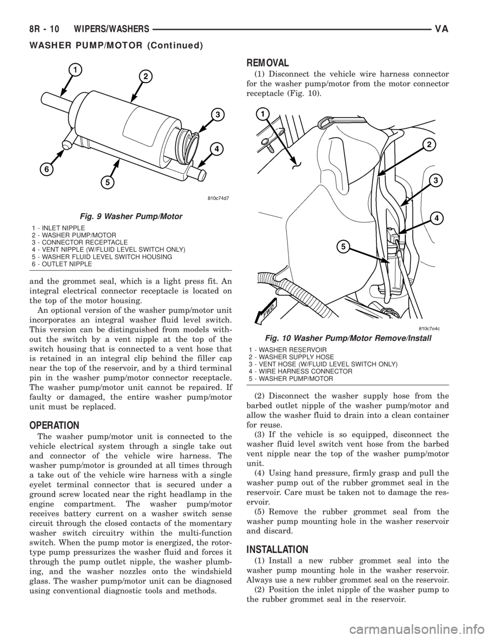
An optional version of the washer pump/motor unit
incorporates an integral washer fluid level switch.
This version can be distinguished from models with-
out the switch by a vent nipple at the top of the
switch housing that is connected to a vent hose that
is retained in an integral clip behind the filler cap
near the top of the reservoir, and by a third terminal
pin in the washer pump/motor connector receptacle.
The washer pump/motor unit cannot be repaired. If
faulty or damaged, the entire washer pump/motor
unit must be replaced.
OPERATION
The washer pump/motor unit is connected to the
vehicle electrical system through a single take out
and connector of the vehicle wire harness. The
washer pump/motor is grounded at all times through
a take out of the vehicle wire harness with a single
eyelet terminal connector that is secured under a
ground screw located near the right headlamp in the
engine compartment. The washer pump/motor
receives battery current on a washer switch sense
circuit through the closed contacts of the momentary
washer switch circuitry within the multi-function
switch. When the pump motor is energized, the rotor-
type pump pressurizes the washer fluid and forces it
through the pump outlet nipple, the washer plumb-
ing, and the washer nozzles onto the windshield
glass. The washer pump/motor unit can be diagnosed
using conventional diagnostic tools and methods.
REMOVAL
(1) Disconnect the vehicle wire harness connector
for the washer pump/motor from the motor connector
receptacle (Fig. 10).
(2) Disconnect the washer supply hose from the
barbed outlet nipple of the washer pump/motor and
allow the washer fluid to drain into a clean container
for reuse.
(3) If the vehicle is so equipped, disconnect the
washer fluid level switch vent hose from the barbed
vent nipple near the top of the washer pump/motor
unit.
(4) Using hand pressure, firmly grasp and pull the
washer pump out of the rubber grommet seal in the
reservoir. Care must be taken not to damage the res-
ervoir.
(5) Remove the rubber grommet seal from the
washer pump mounting hole in the washer reservoir
and discard.
INSTALLATION
(1)Install a new rubber grommet seal into the
washer pump mounting hole in the washer reservoir.
Always use a new rubber grommet seal on the reservoir.
(2) Position the inlet nipple of the washer pump to
the rubber grommet seal in the reservoir.
Fig. 9 Washer Pump/Motor
1 - INLET NIPPLE
2 - WASHER PUMP/MOTOR
3 - CONNECTOR RECEPTACLE
4 - VENT NIPPLE (W/FLUID LEVEL SWITCH ONLY)
5 - WASHER FLUID LEVEL SWITCH HOUSING
6 - OUTLET NIPPLE
Fig. 10 Washer Pump/Motor Remove/Install
1 - WASHER RESERVOIR
2 - WASHER SUPPLY HOSE
3 - VENT HOSE (W/FLUID LEVEL SWITCH ONLY)
4 - WIRE HARNESS CONNECTOR
5 - WASHER PUMP/MOTOR
8R - 10 WIPERS/WASHERSVA
WASHER PUMP/MOTOR (Continued)
Page 296 of 1232
OPERATION
The wiper arms are designed to mechanically
transmit the motion from the wiper pivots to the
wiper blades. The wiper arm must be properly
indexed to the wiper pivot in order to maintain the
proper wiper blade travel on the glass. The tapered
mounting hole in the wiper arm pivot end interlocks
with the serrations on the outer circumference of the
wiper pivot shaft, allowing positive engagement and
finite adjustment of this connection. The mounting
nut locks the wiper arm to the threaded end of the
wiper pivot shaft. The spring-loaded wiper arm hinge
controls the down-force applied through the tip of the
wiper arm to the wiper blade on the glass. The hook
formation on the tip of the wiper arm provides a cra-
dle for securing and latching the wiper blade pivot
block to the wiper arm.
REMOVAL
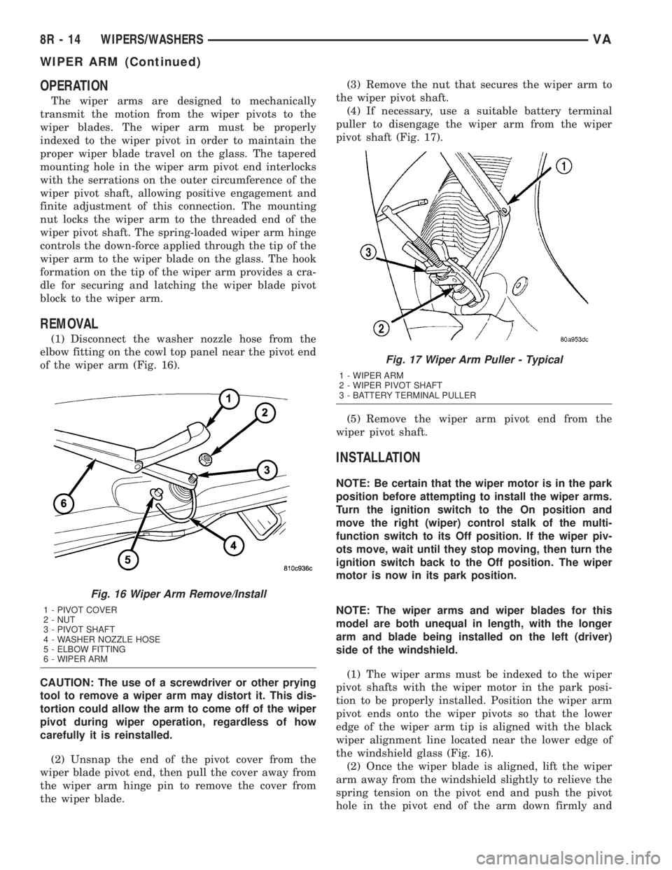
(1) Disconnect the washer nozzle hose from the
elbow fitting on the cowl top panel near the pivot end
of the wiper arm (Fig. 16).
CAUTION: The use of a screwdriver or other prying
tool to remove a wiper arm may distort it. This dis-
tortion could allow the arm to come off of the wiper
pivot during wiper operation, regardless of how
carefully it is reinstalled.
(2) Unsnap the end of the pivot cover from the
wiper blade pivot end, then pull the cover away from
the wiper arm hinge pin to remove the cover from
the wiper blade.(3) Remove the nut that secures the wiper arm to
the wiper pivot shaft.
(4) If necessary, use a suitable battery terminal
puller to disengage the wiper arm from the wiper
pivot shaft (Fig. 17).
(5) Remove the wiper arm pivot end from the
wiper pivot shaft.
INSTALLATION
NOTE: Be certain that the wiper motor is in the park
position before attempting to install the wiper arms.
Turn the ignition switch to the On position and
move the right (wiper) control stalk of the multi-
function switch to its Off position. If the wiper piv-
ots move, wait until they stop moving, then turn the
ignition switch back to the Off position. The wiper
motor is now in its park position.
NOTE: The wiper arms and wiper blades for this
model are both unequal in length, with the longer
arm and blade being installed on the left (driver)
side of the windshield.
(1) The wiper arms must be indexed to the wiper
pivot shafts with the wiper motor in the park posi-
tion to be properly installed. Position the wiper arm
pivot ends onto the wiper pivots so that the lower
edge of the wiper arm tip is aligned with the black
wiper alignment line located near the lower edge of
the windshield glass (Fig. 16).
(2) Once the wiper blade is aligned, lift the wiper
arm away from the windshield slightly to relieve the
spring tension on the pivot end and push the pivot
hole in the pivot end of the arm down firmly and
Fig. 16 Wiper Arm Remove/Install
1 - PIVOT COVER
2 - NUT
3 - PIVOT SHAFT
4 - WASHER NOZZLE HOSE
5 - ELBOW FITTING
6 - WIPER ARM
Fig. 17 Wiper Arm Puller - Typical
1 - WIPER ARM
2 - WIPER PIVOT SHAFT
3 - BATTERY TERMINAL PULLER
8R - 14 WIPERS/WASHERSVA
WIPER ARM (Continued)
Page 305 of 1232
WIRING
TABLE OF CONTENTS
page page
WIRING DIAGRAM INFORMATION....... 8W-01-1
COMPONENT INDEX.................. 8W-02-1
POWER DISTRIBUTION............... 8W-10-1
FUSE BLOCK........................ 8W-11-1
GROUND DISTRIBUTION.............. 8W-15-1
BUS COMMUNICATIONS.............. 8W-18-1
CHARGING SYSTEM.................. 8W-20-1
STARTING SYSTEM.................. 8W-21-1
FUEL/IGNITION SYSTEM.............. 8W-30-1
TRANSMISSION CONTROL SYSTEM..... 8W-31-1
VEHICLE SPEED CONTROL............ 8W-33-1
ANTILOCK BRAKES................... 8W-35-1
VEHICLE THEFT SECURITY SYSTEM..... 8W-39-1
INSTRUMENT CLUSTER............... 8W-40-1
HORN/CIGAR LIGHTER................ 8W-41-1
AIR CONDITIONER/HEATER............ 8W-42-1
AIRBAG SYSTEM.................... 8W-43-1
INTERIOR LIGHTING.................. 8W-44-1CENTRAL TIMER MODULE............. 8W-45-1
AUDIO SYSTEM..................... 8W-47-1
REAR WINDOW DEFOGGER............ 8W-48-1
FRONT LIGHTING.................... 8W-50-1
REAR LIGHTING..................... 8W-51-1
TURN SIGNALS...................... 8W-52-1
WIPERS............................ 8W-53-1
TRAILER TOW....................... 8W-54-1
NAVIGATION/TELECOMMUNICATIONS.... 8W-55-1
POWER WINDOWS................... 8W-60-1
POWER DOOR LOCKS................ 8W-61-1
POWER MIRRORS................... 8W-62-1
POWER SEATS...................... 8W-63-1
SPLICE INFORMATION................ 8W-70-1
CONNECTOR PIN-OUTS............... 8W-80-1
CONNECTOR/GROUND/SPLICE
LOCATION........................ 8W-91-1
POWER DISTRIBUTION............... 8W-97-1 VAWIRING 8W - 1