Page 762 of 3870

5. If the run-out cannot be corrected by changing the phase of the brake disc,
replace the brake disc or grind it with the on-the-car type brake lathe ("MAD,
DL-8700PF" or equivalent). MASTER CYLINDER FUNCTION CHECK 1. Remove the reservoir cap.
2. While watching the open reservoir from a distance of 50 cm (20 inches), have
an assistant depress the brake pedal. If there was a stream of brake fluid rising
from the reservoir, proceed to Step 3. If there was no stream of brake fluid
rising from the reservoir, repair or replace the master cylinder.
3. While watching the open reservoir from a distance of 50 cm (20 inches), have
the assistant release the brake pedal. If there was a small amount of air bubbles
rising through the brake fluid, master cylinder function is normal. If there were
no bubbles rising through the brake fluid, repair or replace the master cylinder. BRAKE PEDAL REMOVAL AND INSTALLATION
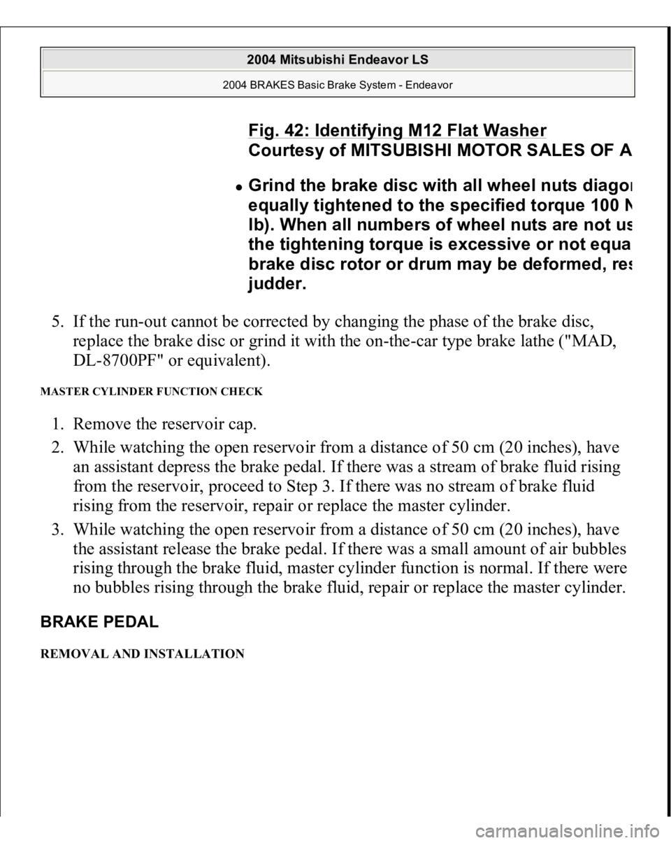
Fig. 42: Identifying M12 Flat Washer
Courtes
y of MITSUBISHI MOTOR SALES OF
A
Grind the brake disc with all wheel nuts dia
gon
equall
y tightened to the specified torque 100
N
lb). When all numbers of wheel nuts are not u
s
the ti
ghtenin
g torque is excessive or not equa
brake disc rotor or drum ma
y be deformed, re
s
judder.
2004 Mitsubishi Endeavor LS
2004 BRAKES Basic Brake System - Endeavor
Page 774 of 3870
Fig. 52: Removing/Installing Disc Brake Assembly
Courtesy of MITSUBISHI MOTOR SALES OF AMERICA.
INSTALLATION SERVICE POINT >>A<< BRAKE CALIPER ASSEMBLY INSTALLATION 1. In order to measure the brake drag force, measure the hub torque with the pads
removed by the following procedure. Use a spring scale to measure the hub
2004 Mitsubishi Endeavor LS
2004 BRAKES Basic Brake System - Endeavor
Page 775 of 3870
torque in the forward direction. Record hub torque with pads removed.
Fig. 53: Measuring Hub Torque Without Pads
Courtesy of MITSUBISHI MOTOR SALES OF AMERICA.
2. After re-installing the caliper support to the knuckle, install the pad clips and
the pads to the caliper support.
3. Clean the piston and insert into cylinder with special tool MB990520.
4. Be careful that the piston boot does not become caught, when lowering the
caliper assembly and installing the lock pin bolt.
5. Check the brake drag force as follows.
CAUTION: Do not let any oil, grease or other contamination
get onto the friction surfaces of the pads and
brake discs.
2004 Mitsubishi Endeavor LS
2004 BRAKES Basic Brake System - Endeavor
Page 776 of 3870
1. Start the engine and hold the brake pedal down for 5 seconds. [Pedal
depression force: approximately 200 N (45 pound)]
2. Stop the engine.
3. Turn the brake disc forward 10 times.
4. Use a spring scale to measure the hub torque with pads installed in the
same direction as earlier.
5. Calculate the drag force of the disc brake [difference between hub torque
with pads installed and hub torque with pads removed].
Standard value: 68 N (15 pounds) or less
Fig. 54: Measuring Drag Force
Courtes
y of MITSUBISHI MOTOR SALES OF AMERICA
.
2004 Mitsubishi Endeavor LS
2004 BRAKES Basic Brake System - Endeavor
Page 777 of 3870
6. If the brake drag force exceeds the standard value, disassemble and clean the
piston. Check for corrosion or worn piston seal, and check the sliding condition
of the lock pin and guide pin.
Fig. 55: Measuring Hub Torque With Pads
Courtesy of MITSUBISHI MOTOR SALES OF AMERICA.
INSPECTION BRAKE DISC CHECK
Disc wear (Refer to DISC BRAKE ROTOR CHECK
).
Disc run-out (Refer to DISC BRAKE ROTOR CHECK
).
DISASSEMBLY AND ASSEMBLY < FRONT>
2004 Mitsubishi Endeavor LS
2004 BRAKES Basic Brake System - Endeavor
Page 1007 of 3870
DOOR FIT ADJUSTMENT Required Special Tools:
MB990211: Slide Hammer MB990243: Body Puller MB990900 or MB991164: Door adjusting Wrench MB990939: Brass Bar
1. Use special tool MB990900 or MB991164 to loosen the hinge mounting bolts
on the body side, and then adjust the clearance around the door so that it is
uniform on all sides.
CAUTION:
Attach protection tape to the fender and door
edges where the hinge is installed. Do not rotate special tool MB991164 with a
torque of over 98 N.m (72 ft-lb).
2004 Mitsubishi Endeavor LS
2004 BODY & ACCESSORIES Door - Endeavor
Page 1083 of 3870

PROPELLER SHAFT DIAGNOSTIC TROUBLESHOOTING STRATEGYUse these steps to plan your diagnostic strategy. If you follow them carefully, you
will be sure that you have exhausted all of the possible ways to find a propeller
shaft fault.
1. Gather information from the customer.
2. Verify that the condition described by the customer exists.
3. Find the malfunction by following the Symptom Chart.
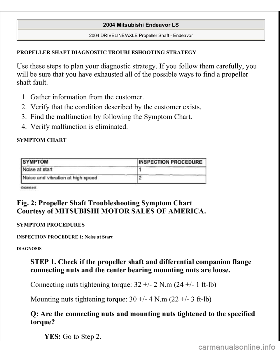
4. Verify malfunction is eliminated. SYMPTOM CHART Fig. 2: Propeller Shaft Troubleshooting Symptom Chart
Courtesy of MITSUBISHI MOTOR SALES OF AMERICA.
SYMPTOM PROCEDURES INSPECTION PROCEDURE 1: Noise at Start DIAGNOSIS
STEP 1. Check if the propeller shaft and differential companion flange
connecting nuts and the center bearing mounting nuts are loose.
Connecting nuts tightening torque: 32 +/- 2 N.m (24 +/- 1 ft-lb)
Mounting nuts tightening torque: 30 +/- 4 N.m (22 +/- 3 ft-lb)
Q: Are the connecting nuts and mounting nuts tightened to the specified
torque?
YES: Go to Ste
p 2.
2004 Mitsubishi Endeavor LS
2004 DRIVELINE/AXLE Propeller Shaft - Endeavor
Page 1084 of 3870
NO: Tighten the connecting nuts and mounting nuts to the specified
torque. Then go to Step 3 .
STEP 2. Check the sleeve yoke's spline of front propeller shaft for wear.
Q: Is wear apparent?
YES: Replace the propeller shaft. Then go to Step 3.
NO: Go to Step 3.
STEP 3. Retest the system.
Q: Is the abnormal noise eliminated?
YES: The procedure is complete.
NO: Recheck from Step 1 .
INSPECTION PROCEDURE 2: Noise and Vibration at High Speed DIAGNOSIS
STEP 1. Check the propeller shaft run-out.
1. Remove the propeller shaft. (Refer to PROPELLER SHAFT
.)
2. Measure the propeller shaft runout.
Limit: 0.6 mm (0.02 inch)
2004 Mitsubishi Endeavor LS
2004 DRIVELINE/AXLE Propeller Shaft - Endeavor