Page 1094 of 3870

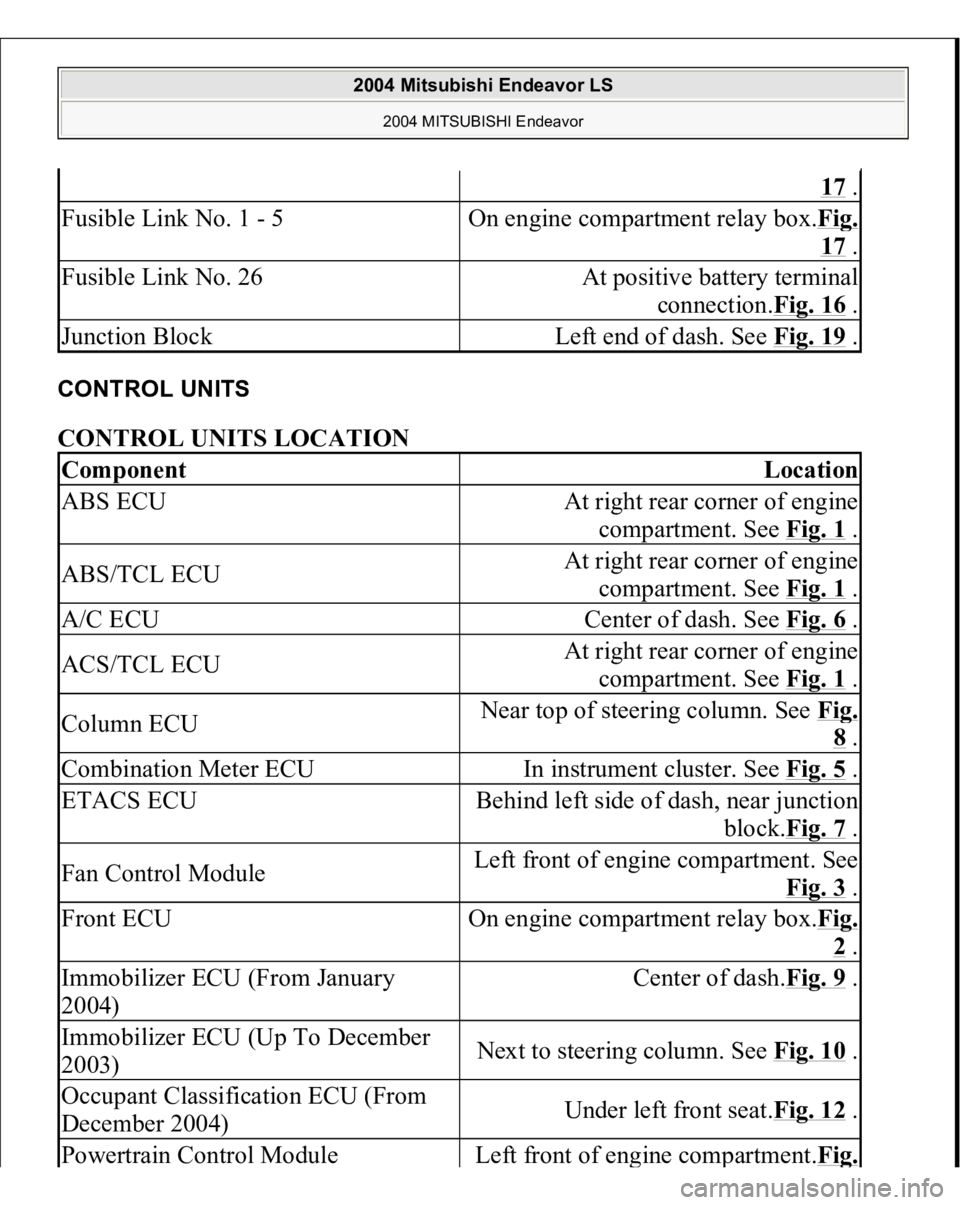
CONTROL UNITS CONTROL UNITS LOCATION
17 .
Fusible Link No. 1 - 5
On engine compartment relay box.Fi
g.
17 .
Fusible Link No. 26
At positive battery terminal
connection.Fig. 16
.
Junction Block
Left end of dash. See Fig. 19
.
Component
Location
ABS ECU
At right rear corner of engine
compartment. See Fig. 1
.
ABS/TCL ECU
At right rear corner of engine
compartment. See Fig. 1
.
A/C ECU
Center of dash. See Fig. 6
.
ACS/TCL ECU
At right rear corner of engine
compartment. See Fig. 1
.
Column ECU
Near top of steering column. See Fi
g. 8 .
Combination Meter ECU
In instrument cluster. See Fig. 5
.
ETACS ECU
Behind left side of dash, near junction
block.Fig. 7
.
Fan Control Module
Left front of engine compartment. See
Fig. 3
.
Front ECU
On engine compartment relay box.Fi
g. 2 .
Immobilizer ECU (From January
2004)
Center of dash.Fig. 9
.
Immobilizer ECU (Up To December
2003)
Next to steering column. See Fig. 10
.
Occupant Classification ECU (From
December 2004)
Under left front seat.Fig. 12
.
Powertrain Control Modul
e
Left front of en
gine com
partment.Fi
g.
2004 Mitsubishi Endeavor LS
2004 MITSUBISHI Endeavor
Page 1095 of 3870

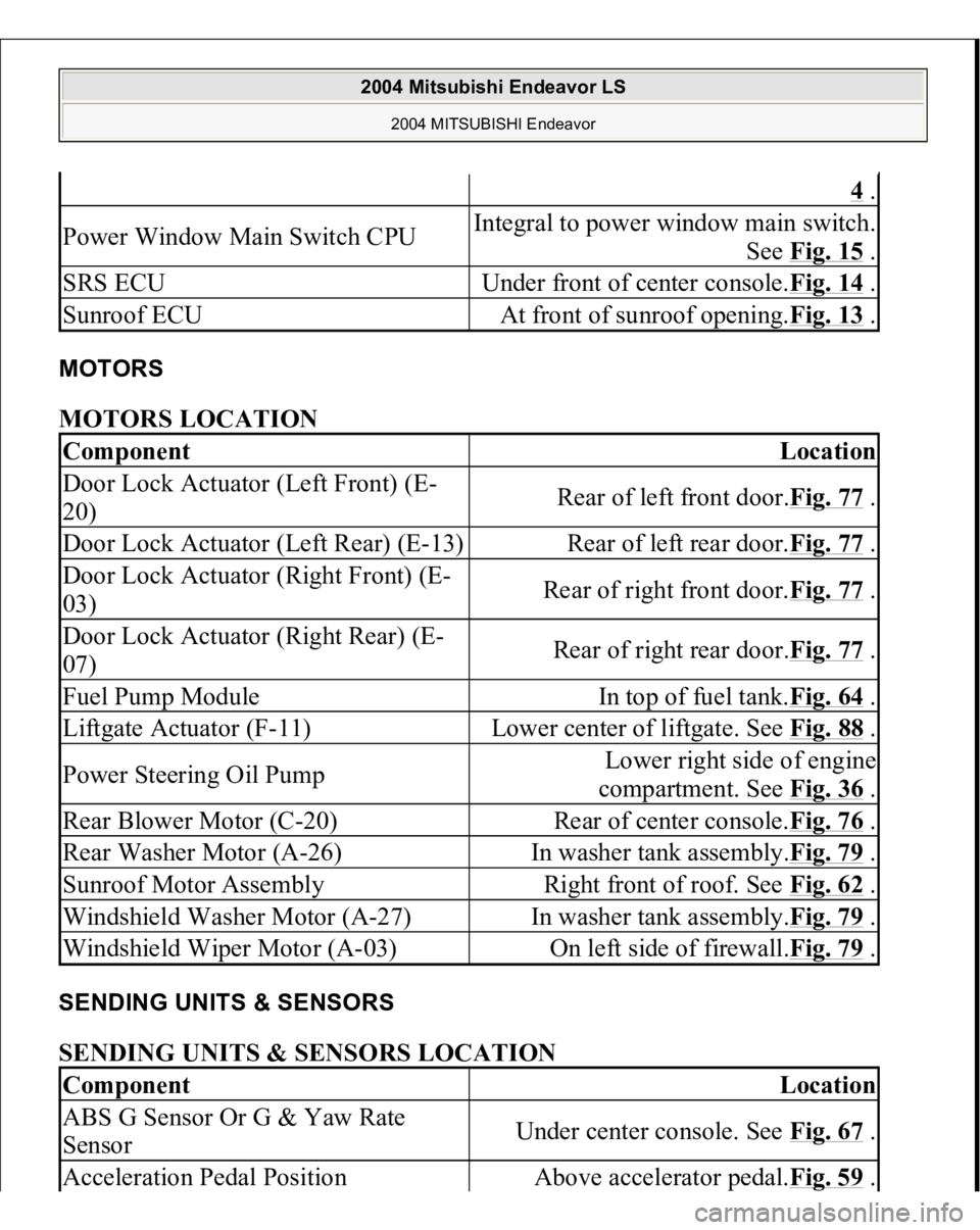
MOTORS MOTORS LOCATION SENDING UNITS & SENSORS SENDING UNITS & SENSORS LOCATION
4 .
Power Window Main Switch CPU
Integral to power window main switch.
See Fig. 15
.
SRS ECU
Under front of center console.Fig. 14
.
Sunroof ECU
At front of sunroof opening.Fig. 13
.
Component
Location
Door Lock Actuator (Left Front) (E-
20)
Rear of left front door.Fig. 77
.
Door Lock Actuator (Left Rear) (E-13)
Rear of left rear door.Fig. 77
.
Door Lock Actuator (Right Front) (E-
03)
Rear of right front door.Fig. 77
.
Door Lock Actuator (Right Rear) (E-
07)
Rear of right rear door.Fig. 77
.
Fuel Pump Module
In top of fuel tank.Fig. 64
.
Liftgate Actuator (F-11)
Lower center of liftgate. See Fig. 88
.
Power Steering Oil Pump
Lower right side of engine
compartment. See Fig. 36
.
Rear Blower Motor (C-20)
Rear of center console.Fig. 76
.
Rear Washer Motor (A-26)
In washer tank assembly.Fig. 79
.
Sunroof Motor Assembly
Right front of roof. See Fig. 62
.
Windshield Washer Motor (A-27)
In washer tank assembly.Fig. 79
.
Windshield Wiper Motor (A-03)
On left side of firewall.Fig. 79
.
Component
Location
ABS G Sensor Or G & Yaw Rate
Sensor
Under center console. See Fig. 67
.
Acceleration Pedal Position
Above accelerator pedal.Fig. 59
.
2004 Mitsubishi Endeavor LS
2004 MITSUBISHI Endeavor
Page 1220 of 3870

Courtesy of MITSUBISHI MOTOR SALES OF AMERICA
.
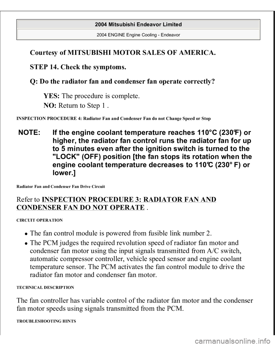
STEP 14. Check the symptoms.
Q: Do the radiator fan and condenser fan operate correctly?
YES: The procedure is complete.
NO: Return to Step 1 .
INSPECTION PROCEDURE 4: Radiator Fan and Condenser Fan do not Change Speed or Stop Radiator Fan and Condenser Fan Drive Circuit Refer to INSPECTION PROCEDURE 3: RADIATOR FAN AND CONDENSER FAN DO NOT OPERATE
.
CIRCUIT OPERATION
The fan control module is powered from fusible link number 2. The PCM judges the required revolution speed of radiator fan motor and
condenser fan motor using the input signals transmitted from A/C switch,
automatic compressor controller, vehicle speed sensor and engine coolant
temperature sensor. The PCM activates the fan control module to drive the
radiator fan motor and condenser fan motor.
TECHNICAL DESCRIPTION The fan controller has variable control of the radiator fan motor and the condenser
fan motor speeds using signals transmitted from the PCM. TROUBLESHOOTING HINTS NOTE: If the engine coolant temperature reaches 110°C (230°F) or
higher, the radiator fan control runs the radiator fan for up
to 5 minutes even after the ignition switch is turned to the
"LOCK" (OFF) position [the fan stops its rotation when the
engine coolant temperature decreases to 110°C (230° F) or
lower.]
2004 Mitsubishi Endeavor Limited 2004 ENGINE Engine Cooling - Endeavor
Page 1239 of 3870

Courtesy of MITSUBISHI MOTOR SALES OF AMERICA
.
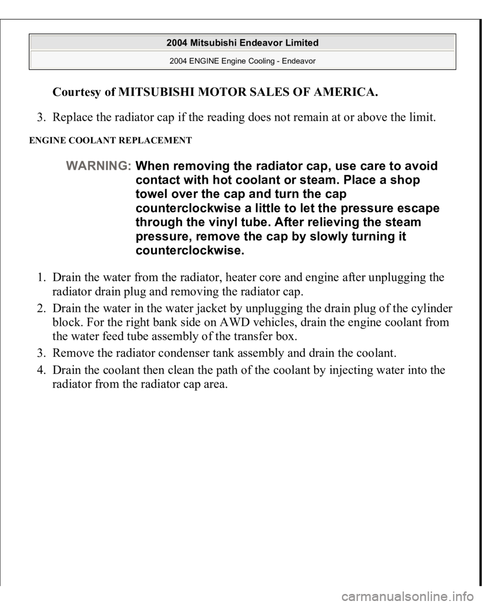
3. Replace the radiator cap if the reading does not remain at or above the limit.
ENGINE COOLANT REPLACEMENT 1. Drain the water from the radiator, heater core and engine after unplugging the
radiator drain plug and removing the radiator cap.
2. Drain the water in the water jacket by unplugging the drain plug of the cylinder
block. For the right bank side on AWD vehicles, drain the engine coolant from
the water feed tube assembly of the transfer box.
3. Remove the radiator condenser tank assembly and drain the coolant.
4. Drain the coolant then clean the path of the coolant by injecting water into the
radiator from the radiator cap area.
WARNING:When removing the radiator cap, use care to avoid
contact with hot coolant or steam. Place a shop
towel over the cap and turn the cap
counterclockwise a little to let the pressure escape
through the vinyl tube. After relieving the steam
pressure, remove the cap by slowly turning it
counterclockwise.
2004 Mitsubishi Endeavor Limited 2004 ENGINE Engine Cooling - Endeavor
Page 1242 of 3870
Fig. 40: Identifying AWD Right Bank
Courtesy of MITSUBISHI MOTOR SALES OF AMERICA.
5. Apply the designated sealant to the screw area of the cylinder block drain plug,
and then tighten to the standard torque.
Specified sealant: 3M (tm) AAD Part No.8731 or equivalent
Tightening torque: 39 +/- 5 N.m (29 +/- 3 ft-lb)
2004 Mitsubishi Endeavor Limited 2004 ENGINE Engine Cooling - Endeavor
Page 1243 of 3870
Fig. 41: Identifying Cylinder Block Drain Plug
Courtesy of MITSUBISHI MOTOR SALES OF AMERICA.
6. Securely tighten the radiator drain plug.
7. Assemble the radiator condenser tank assembly.
8. By referring to the section on coolant, select an appropriate concentration for
safe operating temperature within the range of 30 to 60 %. Use MB991871 to
refill the coolant. A convenient mixture is a 50 % water and 50 % antifreeze
solution [freezing point: -31°C (-32.8 °F)].
Recommended antifreeze: Lon
g Life Antifreeze Coolant or an
CAUTION: Do not use alcohol or methanol anti-freeze or any
engine coolants mixed with alcohol or methanol
anti-freeze. The use of an improper anti-freeze
can cause corrosion of the aluminum
components.
2004 Mitsubishi Endeavor Limited 2004 ENGINE Engine Cooling - Endeavor
Page 1273 of 3870
Fig. 3: Generator Output Line Voltage Drop Test (Typical)
Courtesy of MITSUBISHI MOTOR SALES OF AMERICA.
1. Always be sure to check following before testing:
Generator installation. Generator drive belt tension. Fusible link. Abnormal noise form generator while engine is running.
2. Tune ignition switch to LOCK (OFF) position.
3. Disconnect ne
gative batter
y cable.
WARNING:Battery posts, terminals and related accessories
contain lead and lead compounds. Wash hands
after handling.
2004 Mitsubishi Endeavor Limited
2004 STARTING & CHARGING SYSTEMS Generators & Regulators - Endeavor
Page 1275 of 3870
link). If a terminal is not sufficiently tight or if the harness has become
discolored due to overheating, repair and then test again.
12. After the test, run the engine at idle.
13. Turn off all lights and turn the ignition switch to the LOCK (OFF) position.
14. Disconnect the negative battery cable.
15. Disconnect the ammeter and voltmeter.
16. Connect the negative battery cable.
17. Run engine for 10 minutes at an idle.
OUTPUT CURRENT TEST Required special tool: MB991958: Scan Tool MUT-III Sub Assembly, MB991824:
V.C.I., MB991827 MUT-III USB Cable, MB5991910: MUT-III Main Harness A.
This test determines whether the generator outputs normal current. For best results,
use a char
ging system tester. If not available, follow the ste
ps below. See Fig. 4
.
2004 Mitsubishi Endeavor Limited
2004 STARTING & CHARGING SYSTEMS Generators & Regulators - Endeavor