Page 1096 of 3870

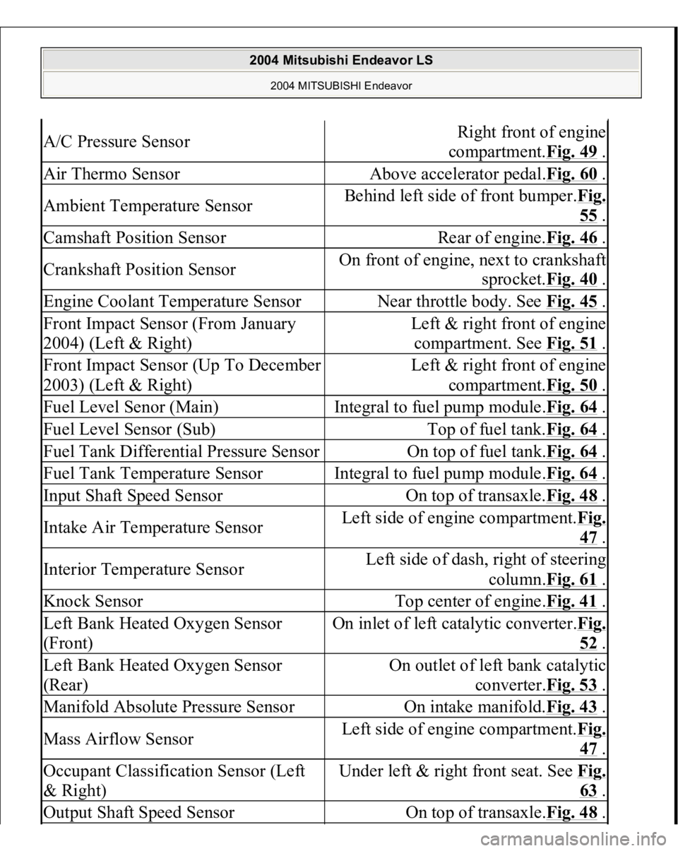
A/C Pressure Sensor
Right front of engine
compartment.Fig. 49
.
Air Thermo Sensor
Above accelerator pedal.Fig. 60
.
Ambient Temperature Sensor
Behind left side of front bumper.Fig.
55 .
Camshaft Position Sensor
Rear of engine.Fig. 46
.
Crankshaft Position Sensor
On front of engine, next to crankshaft
sprocket.Fig. 40
.
Engine Coolant Temperature Sensor
Near throttle body. See Fig. 45
.
Front Impact Sensor (From January
2004) (Left & Right)
Left & right front of engine
compartment. See Fig. 51
.
Front Impact Sensor (Up To December
2003) (Left & Right)
Left & right front of engine
compartment.Fig. 50
.
Fuel Level Senor (Main)
Integral to fuel pump module.Fig. 64
.
Fuel Level Sensor (Sub)
Top of fuel tank.Fig. 64
.
Fuel Tank Differential Pressure Sensor
On top of fuel tank.Fig. 64
.
Fuel Tank Temperature Sensor
Integral to fuel pump module.Fig. 64
.
Input Shaft Speed Sensor
On top of transaxle.Fig. 48
.
Intake Air Temperature Sensor
Left side of engine compartment.Fi
g.
47 .
Interior Temperature Sensor
Left side of dash, right of steering
column.Fig. 61
.
Knock Sensor
Top center of engine.Fig. 41
.
Left Bank Heated Oxygen Sensor
(Front)
On inlet of left catalytic converter.Fi
g.
52 .
Left Bank Heated Oxygen Sensor
(Rear)
On outlet of left bank catalytic
converter.Fig. 53
.
Manifold Absolute Pressure Sensor
On intake manifold.Fig. 43
.
Mass Airflow Sensor
Left side of engine compartment.Fi
g.
47 .
Occupant Classification Sensor (Left
& Right)
Under left & right front seat. See Fi
g.
63 .
Output Shaft Speed Sensor
On top of transaxle.Fig. 48
.
2004 Mitsubishi Endeavor LS
2004 MITSUBISHI Endeavor
Page 1324 of 3870
Fig. 6: Tightening The Crankshaft Bolt To The Specified Torque
Courtesy of MITSUBISHI MOTOR SALES OF AMERICA.
INTAKE MANIFOLD PLENUM AND THROTTLE BODY ASSEMBLY REMOVAL AND INSTALLATION
2004 Mitsubishi Endeavor Limited 2004 ENGINE Engine Overhaul - Endeavor
Page 1325 of 3870
Fig. 7: Removing/Installing Intake Manifold Plenum And Throttle Body Assembly
Cou
rtesy
of MIT
SU
BI
SHI M
OTOR SALE
S OF AMERI
CA.
2004 Mitsubishi Endeavor Limited 2004 ENGINE Engine Overhaul - Endeavor
Page 1360 of 3870
Standard value: 1.0 mm (0.03 inch) or less
Fig. 39: Measuring The Movement Of The Rod
Courtesy of MITSUBISHI MOTOR SALES OF AMERICA.
INTAKE MANIFOLD AND FUEL PARTS REMOVAL AND INSTALLATION < UP TO DECEMBER 2003 >
2004 Mitsubishi Endeavor Limited 2004 ENGINE Engine Overhaul - Endeavor
Page 1361 of 3870
Fig. 40: Removing/Installing Intake Manifold And Fuel Parts
Courtesy of MITSUBISHI MOTOR SALES OF AMERICA.
< FROM JANUARY 2004 >
2004 Mitsubishi Endeavor Limited 2004 ENGINE Engine Overhaul - Endeavor
Page 1362 of 3870
Fig. 41: Removing/Installing Intake Manifold And Fuel Parts (2 Of 2)
Courtesy of MITSUBISHI MOTOR SALES OF AMERICA.
INSTALLATION SERVICE POINTS
>>A<< INTAKE MANIFOLD INSTALLATION 1. Ti
ghten the nuts "R" to 6.5+
/-1.5 N.m
(57+
/-13 i
n-lb
).
2004 Mitsubishi Endeavor Limited 2004 ENGINE Engine Overhaul - Endeavor
Page 1363 of 3870
Fig. 42: Installing Intake Manifold
Courtesy of MITSUBISHI MOTOR SALES OF AMERICA.
2. Tighten the nuts "L" to the specified torque.
Tightening torque: 22+/-1 N.m (16+/-1 ft-lb)
3. Tighten the nuts "R" to the specified torque.
Tightening torque: 22+/-1 N.m (16+/-1 ft-lb)
4. Tighten the nuts "L" to the specified torque.
Tightening torque: 22+/-1 N.m (16+/-1 ft-lb)
5. Ti
ghten the nuts "R" to the s
pecified tor
que.
2004 Mitsubishi Endeavor Limited 2004 ENGINE Engine Overhaul - Endeavor
Page 1379 of 3870
Fig. 57: Fitting Special Tool MD998443 To Lash Adjuster
Courtesy of MITSUBISHI MOTOR SALES OF AMERICA.
>>C<< ROCKER ARMS AND SHAFT INSTALLATION 1. Position the end with the larger chamfer at the right on the front bank, and at
the left on the rear bank.
2. Position the side with the oil holes on the lower side
(cylinder head side
).
NOTE: The side with the four bolt holes is on the intake side.
2004 Mitsubishi Endeavor Limited 2004 ENGINE Engine Overhaul - Endeavor