Page 1051 of 3870
DOOR LOCK KEY CYLINDER SWITCH CHECK DOOR LOCK KEY CYLINDER SWITCH CHECK At the "LOCK" position
1-2
Open circuit
At the "UNLOCK"
position
1-2
Less than 2 ohms
SWITCH POSITION
TESTER CONNECTION
SPECIFIED
CONDITION
LOCK
2-3
Less than 2 ohms
NEUTRAL (OFF)
1-2, 2-3
Open circuit
UNLOCK
1-2
Less than 2 ohms
2004 Mitsubishi Endeavor LS
2004 BODY & ACCESSORIES Door - Endeavor
Page 1052 of 3870
Fig. 36: Locating Door Lock Key Cylinder Switch
Courtesy of MITSUBISHI MOTOR SALES OF AMERICA.
CENTRAL DOOR LOCK SWITCH CONTINUITY CHECK Remove the power window switch (Refer to DOOR GLASS AND REGULATOR
).
< DRIVER'S SIDE >
2004 Mitsubishi Endeavor LS
2004 BODY & ACCESSORIES Door - Endeavor
Page 1053 of 3870
CENTRAL DOOR LOCK SWITCH CONTINUITY CHEC
K
Fig. 37: Identifying Door Lock Switch (Driver Side)
Courtesy of MITSUBISHI MOTOR SALES OF AMERICA.
< PASSENGER'S SIDE > CENTRAL DOOR LOCK SWITCH CONTINUITY CHECK SWITCH POSITION
TESTER CONNECTION
SPECIFIED
CONDITION
LOCK
5-12
Less than 2 ohms
OFF
5-12, 10-12
Open circuit
UNLOCK
10-12
Less than 2 ohms
2004 Mitsubishi Endeavor LS
2004 BODY & ACCESSORIES Door - Endeavor
Page 1054 of 3870
Fig. 38: Identifying Door Lock Switch (Passenger Side)
Courtesy of MITSUBISHI MOTOR SALES OF AMERICA.
WINDOW GLASS RUNCHANNEL AND DOOR OPENING WEATHERSTRIP REMOVAL AND INSTALLATION SWITCH POSITION
TESTER CONNECTION
SPECIFIED
CONDITION
LOCK
1-2
Less than 2 ohms
OFF
1-2, 2-3
Open circuit
UNLOCK
2-3
Less than 2 ohms
2004 Mitsubishi Endeavor LS
2004 BODY & ACCESSORIES Door - Endeavor
Page 1067 of 3870
Fig. 1: Bleeding Cooling System
Courtesy of MITSUBISHI MOTOR SALES OF AMERICA.
ADJUSTMENTS CHECKING DRIVE BELTS Using a Scan Tool (Frequency) 1. Connect Belt Tension Meter Set (MB991668) to Scan Tool (MB991958). See
Fig. 2
.
2. Connect Scan Tool
(MB991958
) to the Data Link Connector
(DLC
). See Fi
g.
CAUTION: To prevent damage, always turn the ignition switch
to the LOCK position before connecting or
disconnecting Scan Tool (MB991958).
2004 Mitsubishi Endeavor Limited
2004 ENGINE COOLING Specifications & Drive Belt Routing - Endeavor
Page 1077 of 3870
1. Loosen the tensioner pulley fixing bolt. See Fig. 9
.
2. Temporarily tighten the tensioner pulley fixing nut to 7-15 ft. lbs. (10-20 N.m).
Ensure belt frequency, tension, or deflection is to specification. See DRIVE
BELT ADJUSTMENT SPECIFICATIONS
table.
Fig. 9: Adjusting Generator Drive Belt
Courtesy of MITSUBISHI MOTOR SALES OF AMERICA.
Power Steering Pump Belt 1. Loosen the tensioner pulley lock nut. See Fig. 10
.
NOTE: The tension will increase when the turning the adjusting
bolt clockwise, and decrease when turning adjusting
bolt counterclockwise.
2004 Mitsubishi Endeavor Limited
2004 ENGINE COOLING Specifications & Drive Belt Routing - Endeavor
Page 1078 of 3870
2. Adjust the belt vibration frequency, tension, or deflection amount using the
adjusting bolt according to specifications. See Fig. 10
. See DRIVE BELT
ADJUSTMENT SPECIFICATIONS
table.
3. Tighten the lock nut to 29-43 ft. lbs. See Fig. 10
.
4. Tighten the adjusting bolt to 35-53 INCH lbs. (4-6 N.m). See Fig. 10
.
5. Check the belt vibration frequency, tension, or deflection and readjust as
necessary. See DRIVE BELT ADJUSTMENT SPECIFICATIONS table.
Fig. 10: Adjusting Power Steering Pump Drive Belt
Courtesy of MITSUBISHI MOTOR SALES OF AMERICA.
DRIVE BELT ROUTIN
G
CAUTION: Check after turning the crankshaft one or more
rotations clockwise.
2004 Mitsubishi Endeavor Limited
2004 ENGINE COOLING Specifications & Drive Belt Routing - Endeavor
Page 1093 of 3870

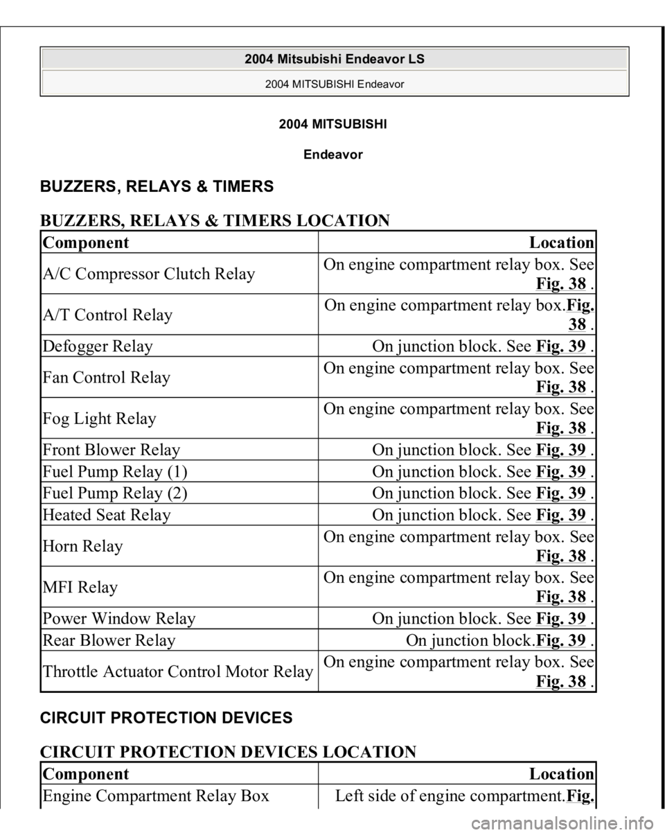
2004 MITSUBISH
I
Endeavor
BUZZERS, RELAYS & TIMERS BUZZERS, RELAYS & TIMERS LOCATION CIRCUIT PROTECTION DEVICES CIRCUIT PROTECTION DEVICES LOCATION Component
Location
A/C Compressor Clutch Relay
On engine compartment relay box. See
Fig. 38
.
A/T Control Relay
On engine compartment relay box.Fig.
38 .
Defogger Relay
On junction block. See Fig. 39
.
Fan Control Relay
On engine compartment relay box. See
Fig. 38
.
Fog Light Relay
On engine compartment relay box. See
Fig. 38
.
Front Blower Relay
On junction block. See Fig. 39
.
Fuel Pump Relay (1)
On junction block. See Fig. 39
.
Fuel Pump Relay (2)
On junction block. See Fig. 39
.
Heated Seat Relay
On junction block. See Fig. 39
.
Horn Relay
On engine compartment relay box. See
Fig. 38
.
MFI Relay
On engine compartment relay box. See
Fig. 38
.
Power Window Relay
On junction block. See Fig. 39
.
Rear Blower Relay
On junction block.Fig. 39
.
Throttle Actuator Control Motor Relay
On engine compartment relay box. See
Fig. 38
.
Component
Location
Engine Compartment Relay Box
Left side of engine compartment.Fi
g.
2004 Mitsubishi Endeavor LS
2004 MITSUBISHI Endeavor
2004 Mitsubishi Endeavor LS
2004 MITSUBISHI Endeavor