Page 1277 of 3870

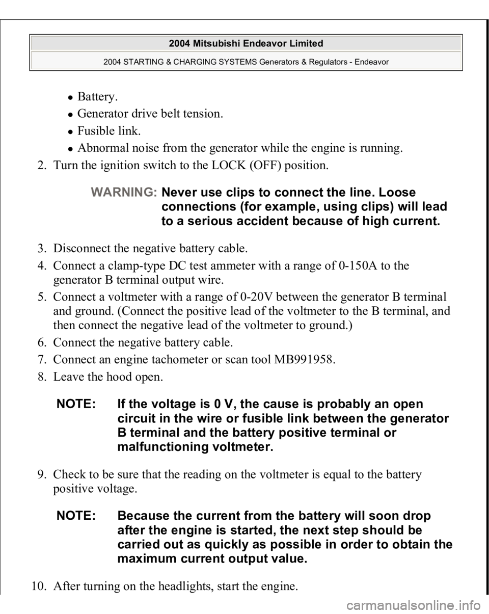
Battery. Generator drive belt tension. Fusible link. Abnormal noise from the generator while the engine is running.
2. Turn the ignition switch to the LOCK (OFF) position.
3. Disconnect the negative battery cable.
4. Connect a clamp-type DC test ammeter with a range of 0-150A to the
generator B terminal output wire.
5. Connect a voltmeter with a range of 0-20V between the generator B terminal
and ground. (Connect the positive lead of the voltmeter to the B terminal, and
then connect the negative lead of the voltmeter to ground.)
6. Connect the negative battery cable.
7. Connect an engine tachometer or scan tool MB991958.
8. Leave the hood open.
9. Check to be sure that the reading on the voltmeter is equal to the battery
positive voltage.
10. After turnin
g on the headli
ghts, start the en
gine.
WARNING:Never use clips to connect the line. Loose
connections (for example, using clips) will lead
to a serious accident because of high current.
NOTE: If the voltage is 0 V, the cause is probably an open
circuit in the wire or fusible link between the generator
B terminal and the battery positive terminal or
malfunctioning voltmeter.
NOTE: Because the current from the battery will soon drop
after the engine is started, the next step should be
carried out as quickly as possible in order to obtain the
maximum current output value.
2004 Mitsubishi Endeavor Limited
2004 STARTING & CHARGING SYSTEMS Generators & Regulators - Endeavor
Page 1278 of 3870

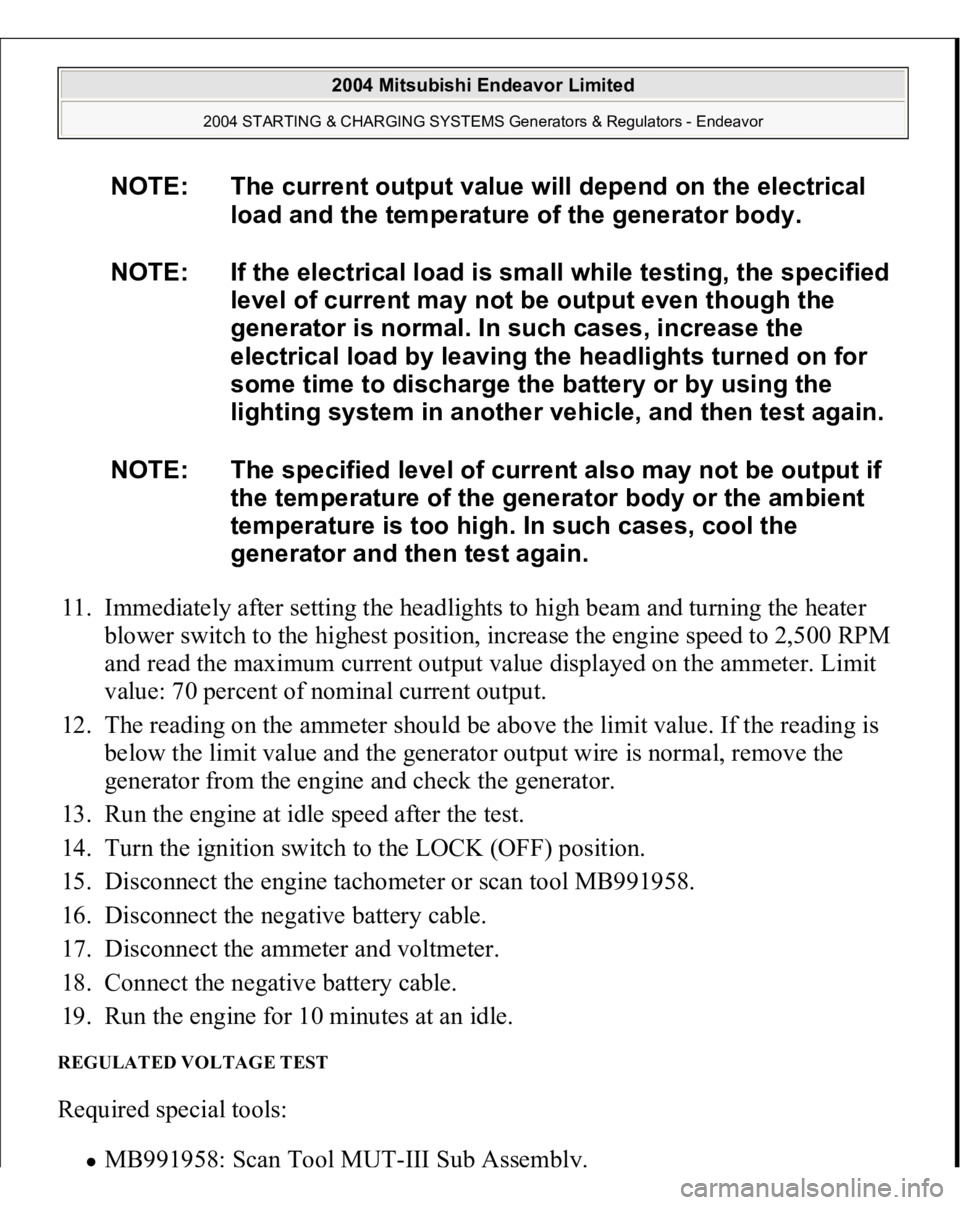
11. Immediately after setting the headlights to high beam and turning the heater
blower switch to the highest position, increase the engine speed to 2,500 RPM
and read the maximum current output value displayed on the ammeter. Limit
value: 70 percent of nominal current output.
12. The reading on the ammeter should be above the limit value. If the reading is
below the limit value and the generator output wire is normal, remove the
generator from the engine and check the generator.
13. Run the engine at idle speed after the test.
14. Turn the ignition switch to the LOCK (OFF) position.
15. Disconnect the engine tachometer or scan tool MB991958.
16. Disconnect the negative battery cable.
17. Disconnect the ammeter and voltmeter.
18. Connect the negative battery cable.
19. Run the engine for 10 minutes at an idle. REGULATED VOLTAGE TEST Required special tools:
MB991958: Scan Tool MUT
-III Sub Assembly.
NOTE: The current output value will depend on the electrical
load and the temperature of the generator body.
NOTE: If the electrical load is small while testing, the specified
level of current may not be output even though the
generator is normal. In such cases, increase the
electrical load by leaving the headlights turned on for
some time to discharge the battery or by using the
lighting system in another vehicle, and then test again.
NOTE: The specified level of current also may not be output if
the temperature of the generator body or the ambient
temperature is too high. In such cases, cool the
generator and then test again.
2004 Mitsubishi Endeavor Limited
2004 STARTING & CHARGING SYSTEMS Generators & Regulators - Endeavor
Page 1280 of 3870

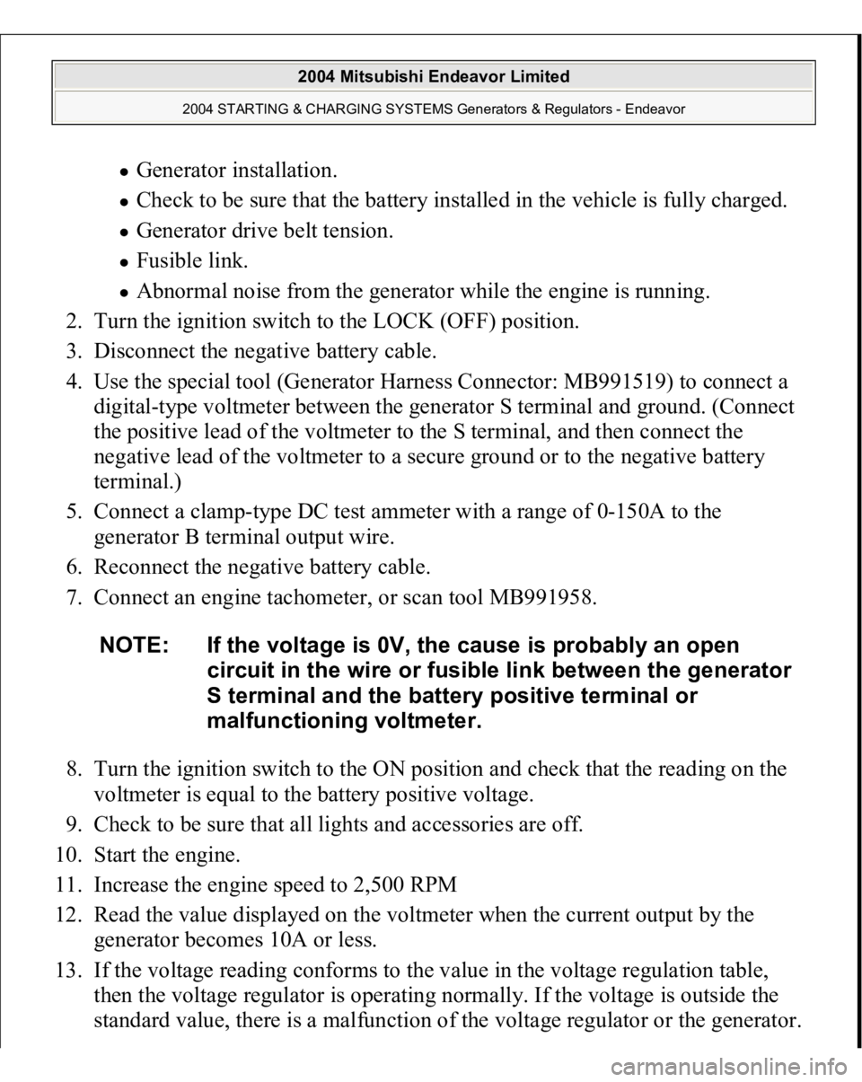
Generator installation. Check to be sure that the battery installed in the vehicle is fully charged. Generator drive belt tension. Fusible link. Abnormal noise from the generator while the engine is running.
2. Turn the ignition switch to the LOCK (OFF) position.
3. Disconnect the negative battery cable.
4. Use the special tool (Generator Harness Connector: MB991519) to connect a
digital-type voltmeter between the generator S terminal and ground. (Connect
the positive lead of the voltmeter to the S terminal, and then connect the
negative lead of the voltmeter to a secure ground or to the negative battery
terminal.)
5. Connect a clamp-type DC test ammeter with a range of 0-150A to the
generator B terminal output wire.
6. Reconnect the negative battery cable.
7. Connect an engine tachometer, or scan tool MB991958.
8. Turn the ignition switch to the ON position and check that the reading on the
voltmeter is equal to the battery positive voltage.
9. Check to be sure that all lights and accessories are off.
10. Start the engine.
11. Increase the engine speed to 2,500 RPM
12. Read the value displayed on the voltmeter when the current output by the
generator becomes 10A or less.
13. If the voltage reading conforms to the value in the voltage regulation table,
then the voltage regulator is operating normally. If the voltage is outside the
standard value, there is a malfunction of the volta
ge re
gulator or the
generator.
NOTE: If the voltage is 0V, the cause is probably an open
circuit in the wire or fusible link between the generator
S terminal and the battery positive terminal or
malfunctioning voltmeter.
2004 Mitsubishi Endeavor Limited
2004 STARTING & CHARGING SYSTEMS Generators & Regulators - Endeavor
Page 1281 of 3870

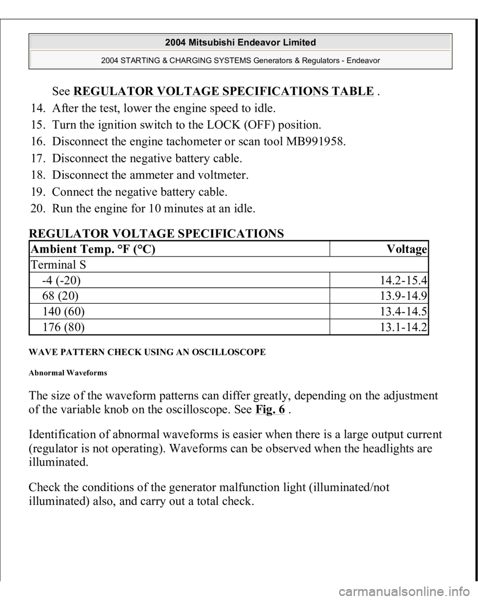
See REGULATOR VOLTAGE SPECIFICATIONS TABLE
.
14. After the test, lower the engine speed to idle.
15. Turn the ignition switch to the LOCK (OFF) position.
16. Disconnect the engine tachometer or scan tool MB991958.
17. Disconnect the negative battery cable.
18. Disconnect the ammeter and voltmeter.
19. Connect the negative battery cable.
20. Run the engine for 10 minutes at an idle.
REGULATOR VOLTAGE SPECIFICATIONS
WAVE PATTERN CHECK USING AN OSCILLOSCOPE Abnormal Waveforms The size of the waveform patterns can differ greatly, depending on the adjustment
of the variable knob on the oscilloscope. See Fig. 6
.
Identification of abnormal waveforms is easier when there is a large output current
(regulator is not operating). Waveforms can be observed when the headlights are
illuminated.
Check the conditions of the generator malfunction light (illuminated/not
illuminated
) also, and carr
y out a total check.
Ambient Temp. °F (°C)
Voltage
Terminal S-4 (-20)
14.2-15.4
68 (20)
13.9-14.9
140 (60)
13.4-14.5
176 (80)
13.1-14.2
2004 Mitsubishi Endeavor Limited
2004 STARTING & CHARGING SYSTEMS Generators & Regulators - Endeavor
Page 1343 of 3870
1. Install special tool MD998769 and the crankshaft pulley washer, and then
tighten the crankshaft bolt.
2. Align the timing mark on the crankshaft sprocket with the timing mark on the
oil pump case, and then rotate the sprocket three teeth counterclockwise.
Fig. 24: Aligning The Timing Mark On Crankshaft Sprocket & Timing
Mark On Oil Pump Case
Courtesy of MITSUBISHI MOTOR SALES OF AMERICA.
3. Align the timing mark on the left bank camshaft sprocket with the timing mark
on the rocker cover.
4. Align the timing mark on the right bank camshaft sprocket with the timing
mark on the rocker cover.
2004 Mitsubishi Endeavor Limited 2004 ENGINE Engine Overhaul - Endeavor
Page 1348 of 3870
Fig. 29: Checking Timing Marks Of All The Sprockets Are In Alignment
Courtesy of MITSUBISHI MOTOR SALES OF AMERICA.
9. Rotate the crankshaft a quarter turn counterclockwise. Then rotate it back
clockwise to verify that all the timing marks are aligned.
10. Loosen the flange bolt securing the tensioner pulley, and then mount special
tool MD998767 and a torque wrench on the tensioner pulley.
11. Torque it to 4.4 N.m (39 in-lb) with the torque wrench.
12. While holding the tensioner pulley in position, tighten the flange bolt to the
specified torque.
Ti
ghtenin
g tor
que: 48+
/-6 N.m (35+
/-4 f
t-lb)
2004 Mitsubishi Endeavor Limited 2004 ENGINE Engine Overhaul - Endeavor
Page 1349 of 3870
Fig. 30: Holding The Tensioner Pulley In Position, Tighten The Flange Bolt
Courtesy of MITSUBISHI MOTOR SALES OF AMERICA.
13. Rotate the crankshaft two turns clockwise and leave it alone for approximately
five minutes.
14. Check to see whether the metal wire inserted when the auto-tensioner was
installed can be removed without any resistance.
If the metal wire can be removed without any resistance, it means that the belt
has a proper tension. Therefore, remove the metal wire. In this condition, check
that the rod protrusion of the auto-tensioner is within the standard value.
Standard value: 4.8 - 6.0 mm (0.19 - 0.24 inch)
2004 Mitsubishi Endeavor Limited 2004 ENGINE Engine Overhaul - Endeavor
Page 1395 of 3870
REMOVAL SERVICE POINTS << A >> CYLINDER HEAD BOLT REMOVAL Use special tool MD998051 to loosen the cylinder head bolt.
Fig. 73: Removing Cylinder Head Bolt
Courtesy of MITSUBISHI MOTOR SALES OF AMERICA.
< > RETAINER LOCK REMOVAL 1. Using special tool MD998735 or MD998772, compress the spring.
2004 Mitsubishi Endeavor Limited 2004 ENGINE Engine Overhaul - Endeavor