Page 1940 of 4500
![LEXUS LS430 2003 Factory Repair Manual Fig. 31: [Disconnecting ECM Connector]
Courtesy of TOYOTA MOTOR SALES, U.S.A., INC.
NG: REPAIR OR REPLACE HARNESS OR CONNECTOR
OK: REPLACE ECM (SEE REPLACEMENT
)
CIRCUIT DESCRIPTION
The ECM det](/manual-img/36/57050/w960_57050-1939.png "LEXUS LS430 2003 Factory Repair Manual Fig. 31: [Disconnecting ECM Connector]
Courtesy of TOYOTA MOTOR SALES, U.S.A., INC.
NG: REPAIR OR REPLACE HARNESS OR CONNECTOR
OK: REPLACE ECM (SEE REPLACEMENT
)
CIRCUIT DESCRIPTION
The ECM det")
Fig. 31: [Disconnecting ECM Connector]
Courtesy of TOYOTA MOTOR SALES, U.S.A., INC.
NG: REPAIR OR REPLACE HARNESS OR CONNECTOR
OK: REPLACE ECM (SEE REPLACEMENT
)
CIRCUIT DESCRIPTION
The ECM detects a cruise control switch signal and sends it to the combination meter via CAN and
BEAN. Then the CRUISE main indicator light comes on.
The CRUISE main indicator light circuit uses CAN and BEAN for communication. If there are any
malfunctions in this circuit, check for DTCs in the CAN communication system and multiplex
communication system.
INSPECTION PROCEDURE
1.PERFORM ACTIVE TEST BY HAND-HELD TESTER
a. Connect the hand-held tester to the DLC3.
b. Check the CRUISE main indicator light by using ACTIVE TEST.
ACTIVE TEST DETAIL (COMBINATION METER ASSY)
OK: Indicator light comes on/goes off.
NG: GO TO COMBINATION METER SYSTEM (SEE HOW TO PROCEED WITH
TROUBLESHOOTING )
OK: Go to next step
2.READ VALUE ON HAND-HELD TESTER
a. Connect the hand-held tester to the DLC3.
b. Turn the ignition switch to the ON position and turn the hand-held tester main switch on.
c. Select the item below in the "DATA LIST", and read the display on the hand-held tester.
DATA LIST (CC (ECM))
ItemVehicle Condition / Test DetailsDiagnostic Note
CRUISE INDIC"CRUISE" indicator is ON / OFF-
ItemMeasurement Item / Display
(Range)Normal ConditionDiagnostic
Note
CCS INDICATOR
MCruise indicator signal (Main
CPU) /ON or OFFON: "CCS READY" ON OFF:
"CCS READY" OFF-
Page 1950 of 4500
HINT:
There is a limitation on laser optical axis adjustment.
Since the laser sensor is installed in the bumper reinforcement, it is important that the laser sensor,
bumper reinforcement, and other related parts are installed properly.
When the sensor is removed from the vehicle for trouble diagnosis or repair, it is necessary to adjust the
laser optical axis after the operation.
1.ADJUST LASER SENSOR
a. Preparation for adjusting the laser optical axis
1. Adjust the tire pressure properly (see INSPECTION
).
2. Luggage in the vehicle, such as in the trunk, should be unloaded.
3. Clean the light-luminous and light-receiving portions of the laser sensor.
HINT:
Prepare a 10 m (32.81 ft) string, with a sharp-pointed weight (plumb bob), and a 5 m (16.41 ft) tape
measure.
Page 1968 of 4500
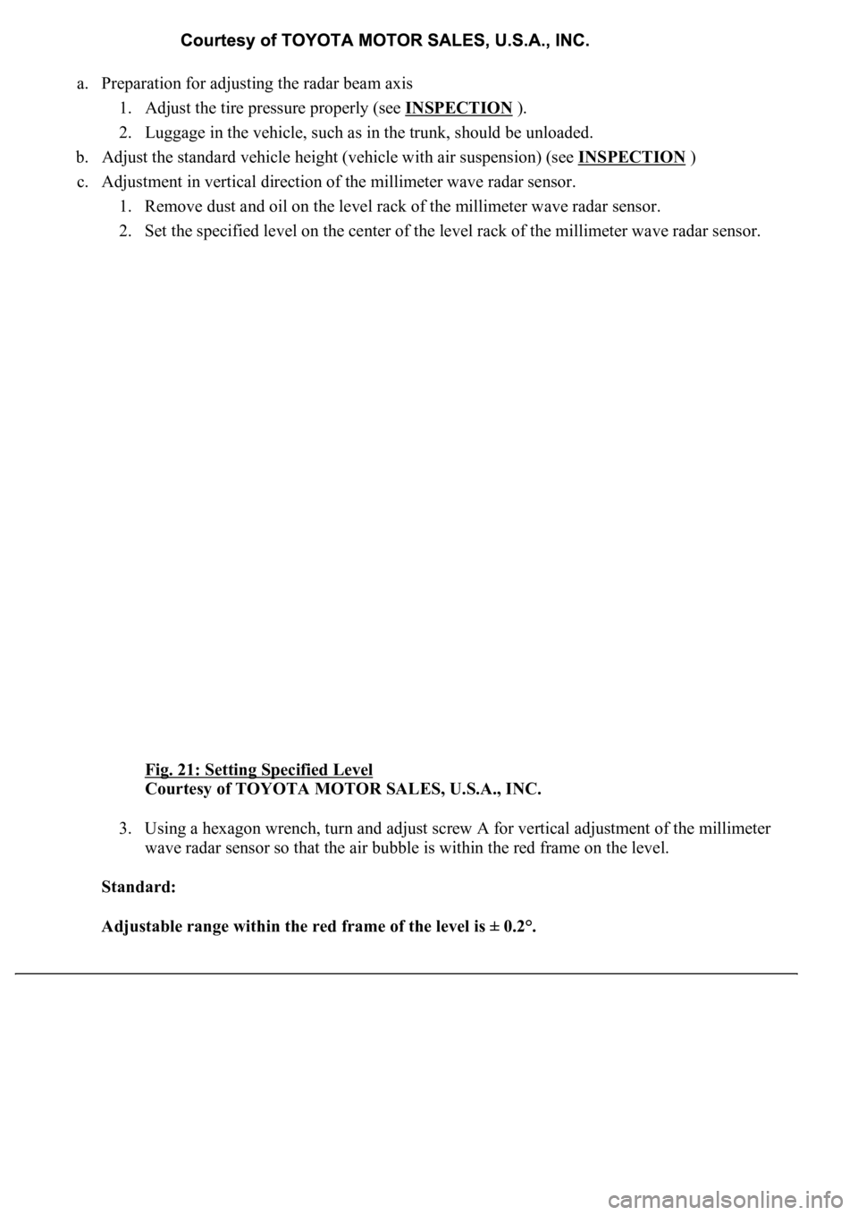
a. Preparation for adjusting the radar beam axis
1. Adjust the tire pressure properly (see INSPECTION
).
2. Luggage in the vehicle, such as in the trunk, should be unloaded.
b. Adjust the standard vehicle height (vehicle with air suspension) (see INSPECTION
)
c. Adjustment in vertical direction of the millimeter wave radar sensor.
1. Remove dust and oil on the level rack of the millimeter wave radar sensor.
2. Set the specified level on the center of the level rack of the millimeter wave radar sensor.
Fig. 21: Setting Specified Level
Courtesy of TOYOTA MOTOR SALES, U.S.A., INC.
3. Using a hexagon wrench, turn and adjust screw A for vertical adjustment of the millimeter
wave radar sensor so that the air bubble is within the red frame on the level.
Standard:
Adjustable range within the red frame of the level is ± 0.2°.
Page 2177 of 4500
a. Fill the rear differential carrier assy with differential gear oil equivalent.
Oil type: Differential synthetic gear oil GL-5 75W-90 or equivalent
Capacity: 1.35 +/- 0.05 liters (1.43 +/- 0.05 US qts, 1.19 +/- 0.04 Imp. qts)
67.INSPECT DIFFERENTIAL OIL (SEE ADJUSTMENT
)
68.INSTALL REAR DIFFERENTIAL FILLER PLUG
a. Using a hexagon wrench (10 mm), install the filler plug with a new gasket.
Torque: 49 N.m (500 kgf.cm, 36 ft.lbf)
69.INSTALL REAR DRIVE SHAFT ASSY LH (SEE REPLACEMENT
)
70.INSTALL REAR DRIVE SHAFT ASSY RH
HINT:
Installation procedure of the RH side is the same as that of the LH side.
71.INSTALL FRONT FLOOR HEAT INSULATOR NO.1
a. Install the front floor heat insulator No.1 with the 4 bolts.
Torque: 5.4 N.m (55 kgf.cm, 48 in..lbf)
72.INSTALL REAR WHEEL
a. Install the rear wheel with the 5 nuts.
Torque: 103 N.m (1,050 kgf.cm, 76 ft.lbf)
73. Install the ornament with the 10 bolts.
Torque: 20 N.m (204 kgf.cm, 15 ft.lbf)
74.INSTALL PROPELLER W/CENTER BEARING SHAFT ASSY (SEE OVERHAUL
)
75.FULLY TIGHTEN CENTER SUPPORT BEARING ASSY NO.1 (SEE OVERHAUL
)
SST 09922-10010
76.INSPECT AND ADJUST NO.2 AND NO.3 JOINT ANGLE (SEE OVERHAUL
)
77.INSTALL PROPELLER SHAFT HEAT INSULATOR (SEE OVERHAUL
)
78.INSTALL EXHAUST PIPE ASSY (SEE REPLACEMENT
)
79.INSTALL OXYGEN SENSOR (SEE REPLACEMENT
)
80.INSPECT AND ADJUST REAR WHEEL ALIGNMENT (SEE ADJUSTMENT
)
81.ADJUST VEHICLE HEIGHT (W/ AIR SUSPENSION) (SEE ON
-VEHICLE INSPECTION )
82.INSPECT HEADLIGHT AIM ONLY (SEE ADJUSTMENT
)
83.CHECK ABS SPEED SENSOR SIGNAL (SEE TEST MODE PROCEDURE
)
84.INSPECT AIR LEAK (W/ AIR SUSPENSION) (SEE REPLACEMENT
)
HINT:
Perform this operation onl
y when the rear differential mount cushion is replaced.
Page 2187 of 4500
2.CUSTOMER PROBLEM ANALYSIS CHECK AND SYMPTOM CHECK
Go To Next Step.
3.INSPECT COMMUNICATION FUNCTION OF LARGE-SCALE MULTIPLEX
COMMUNICATION SYSTEM (BEAN)
a. Use the hand-held tester to check for normal function of the multiplex communication system.
1. (ECU not connected, communication line malfunctioning) Without code outputs, proceed to
A.
2. (ECU not connected, communication line malfunctioning) With code outputs, proceed to B.
B: Go to MULTIPLEX COMMUNICATION SECTION (SEE DIAGNOSTIC TROUBLE CODE
CHART )
A: Go to Next Step.
4.CHECK FOR DTC
a. Check for DTCs and note any codes that are output.
b. Delete the DTC.
c. Recheck for DTCs. Try to prompt the DTC by simulating the original activity that the DTC
suggests.
1. If the DTC does not reoccur, proceed to A
2. If the DTC reoccur, proceed to B
B: Go to step 6
A: Go to Next step
5.(SEE PROBLEM SYMPTOMS TABLE
)
a. If the fault is not listed on the problem symptoms table, proceed to A.
b. If the fault is listed on the problem symptoms table, proceed to B.
B: Go to step 7
A: Go to Next step
6.OVERALL ANALYSIS AND TROUBLESHOOTING
a. (SEE DATA LIST/ACTIVE TEST
).
1. Inspection with the hand-held tester (DATA LIST).
b. (SEE TERMINALS OF ECU
).
c. (SEE ON
-VEHICLE INSPECTION ).
d. (SEE INSPECTION
).
Page 2305 of 4500
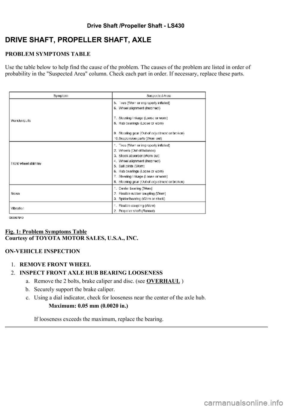
PROBLEM SYMPTOMS TABLE
Use the table below to help find the cause of the problem. The causes of the problem are listed in order of
probability in the "Suspected Area" column. Check each part in order. If necessary, replace these parts.
Fig. 1: Problem Symptoms Table
Courtesy of TOYOTA MOTOR SALES, U.S.A., INC.
ON-VEHICLE INSPECTION
1.REMOVE FRONT WHEEL
2.INSPECT FRONT AXLE HUB BEARING LOOSENESS
a. Remove the 2 bolts, brake caliper and disc. (see OVERHAUL
)
b. Securely support the brake caliper.
c. Using a dial indicator, check for looseness near the center of the axle hub.
Maximum: 0.05 mm (0.0020 in.)
If looseness exceeds the maximum, replace the bearing.
Page 2355 of 4500
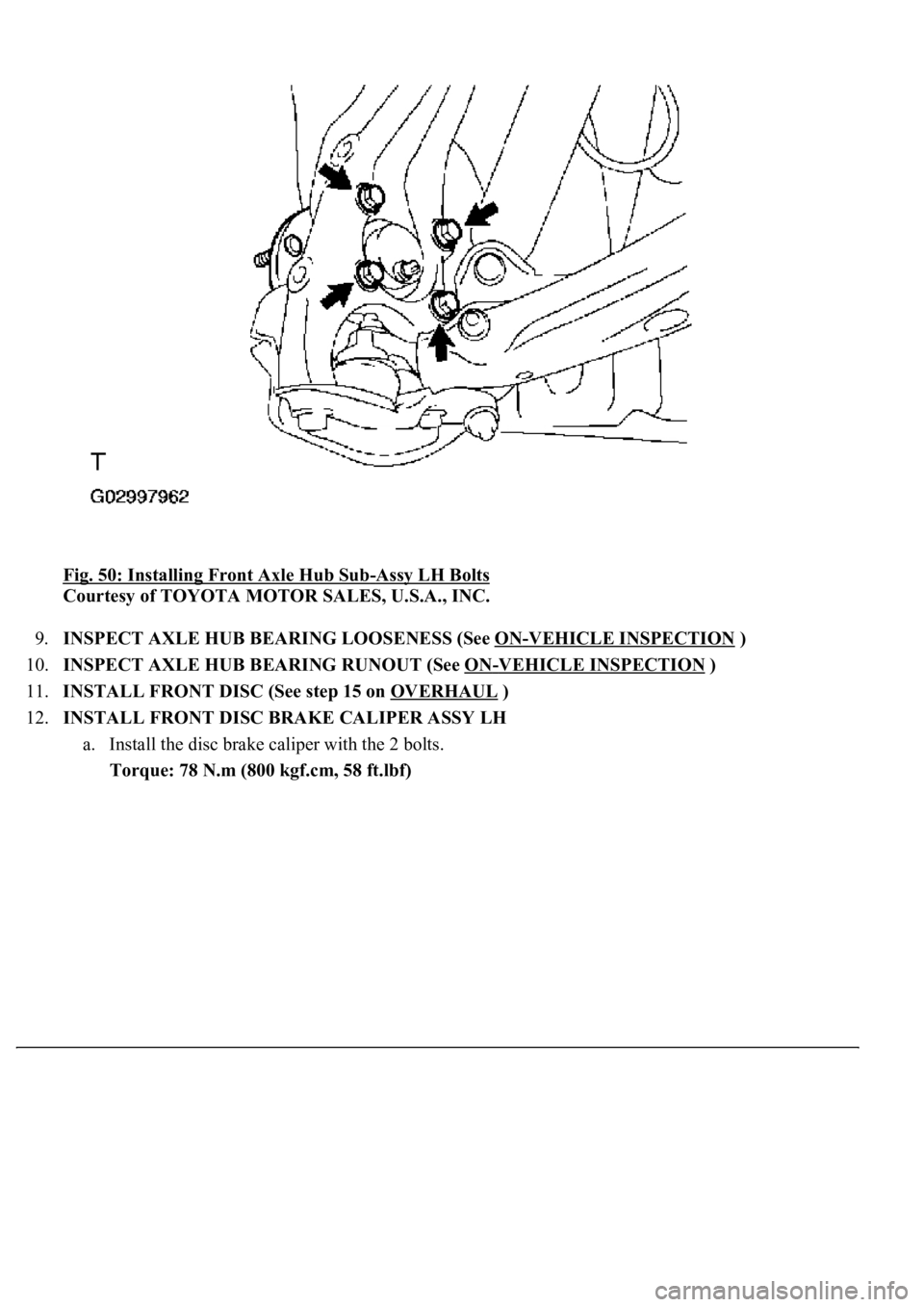
Fig. 50: Installing Front Axle Hub Sub-Assy LH Bolts
Courtesy of TOYOTA MOTOR SALES, U.S.A., INC.
9.INSPECT AXLE HUB BEARING LOOSENESS (See ON
-VEHICLE INSPECTION )
10.INSPECT AXLE HUB BEARING RUNOUT (See ON
-VEHICLE INSPECTION )
11.INSTALL FRONT DISC (See step 15 on OVERHAUL
)
12.INSTALL FRONT DISC BRAKE CALIPER ASSY LH
a. Install the disc brake caliper with the 2 bolts.
Torque: 78 N.m (800 kgf.cm, 58 ft.lbf)
Page 2391 of 4500
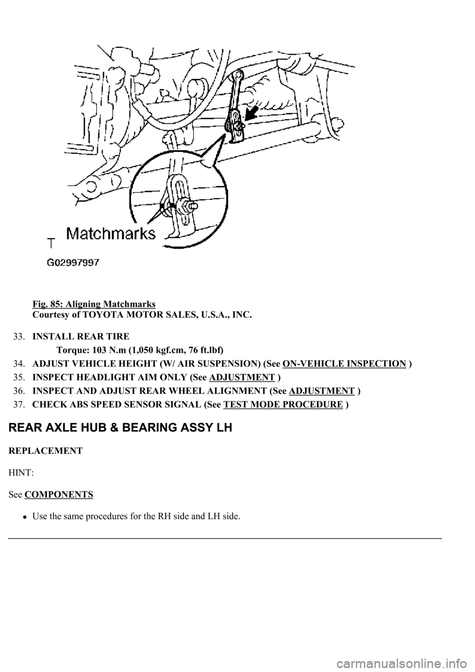
Fig. 85: Aligning Matchmarks
Courtesy of TOYOTA MOTOR SALES, U.S.A., INC.
33.INSTALL REAR TIRE
Torque: 103 N.m (1,050 kgf.cm, 76 ft.lbf)
34.ADJUST VEHICLE HEIGHT (W/ AIR SUSPENSION) (See ON
-VEHICLE INSPECTION )
35.INSPECT HEADLIGHT AIM ONLY (See ADJUSTMENT
)
36.INSPECT AND ADJUST REAR WHEEL ALIGNMENT (See ADJUSTMENT
)
37.CHECK ABS SPEED SENSOR SIGNAL (See TEST MODE PROCEDURE
)
REPLACEMENT
HINT:
See COMPONENTS
<00380056004800030057004b00480003005600440050004800030053005500520046004800470058005500480056000300490052005500030057004b004800030035002b00030056004c0047004800030044005100470003002f002b00030056004c004700
4800110003[