Page 1021 of 4500
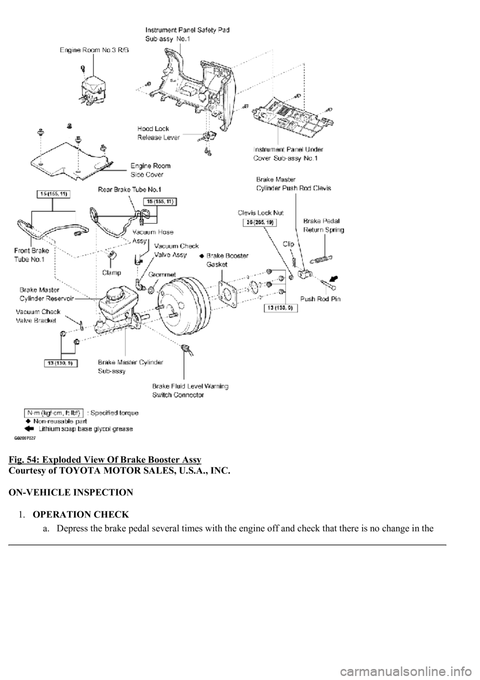
Fig. 54: Exploded View Of Brake Booster Assy
Courtesy of TOYOTA MOTOR SALES, U.S.A., INC.
ON-VEHICLE INSPECTION
1.OPERATION CHECK
a. Depress the brake pedal several times with the en
gine off and check that there is no change in the
Page 1036 of 4500
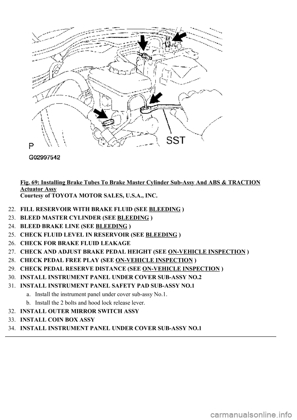
Fig. 69: Installing Brake Tubes To Brake Master Cylinder Sub-Assy And ABS & TRACTION
Actuator Assy
Courtesy of TOYOTA MOTOR SALES, U.S.A., INC.
22.FILL RESERVOIR WITH BRAKE FLUID (SEE BLEEDING
)
23.BLEED MASTER CYLINDER (SEE BLEEDING
)
24.BLEED BRAKE LINE (SEE BLEEDING
)
25.CHECK FLUID LEVEL IN RESERVOIR (SEE BLEEDING
)
26.CHECK FOR BRAKE FLUID LEAKAGE
27.CHECK AND ADJUST BRAKE PEDAL HEIGHT (SEE ON
-VEHICLE INSPECTION )
28.CHECK PEDAL FREE PLAY (SEE ON
-VEHICLE INSPECTION )
29.CHECK PEDAL RESERVE DISTANCE (SEE ON
-VEHICLE INSPECTION )
30.INSTALL INSTRUMENT PANEL UNDER COVER SUB-ASSY NO.2
31.INSTALL INSTRUMENT PANEL SAFETY PAD SUB-ASSY NO.1
a. Install the instrument panel under cover sub-assy No.1.
b. Install the 2 bolts and hood lock release lever.
32.INSTALL OUTER MIRROR SWITCH ASSY
33.INSTALL COIN BOX ASSY
34.INSTALL INSTRUMENT PANEL UNDER COVER SUB-ASSY NO.1
Page 1050 of 4500
HINT:
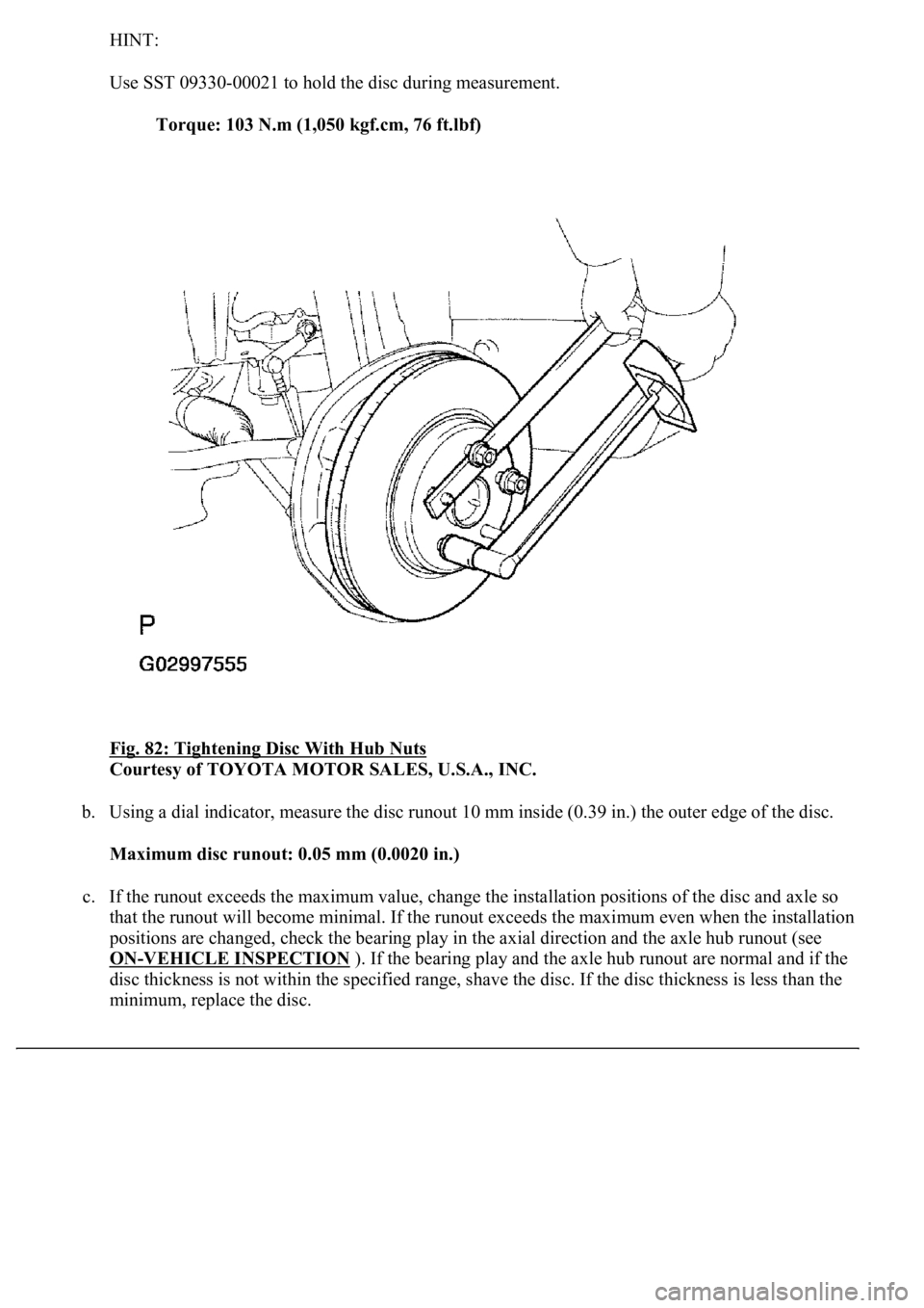
Use SST 09330-00021 to hold the disc during measurement.
Torque: 103 N.m (1,050 kgf.cm, 76 ft.lbf)
Fig. 82: Tightening Disc With Hub Nuts
Courtesy of TOYOTA MOTOR SALES, U.S.A., INC.
b. Using a dial indicator, measure the disc runout 10 mm inside (0.39 in.) the outer edge of the disc.
Maximum disc runout: 0.05 mm (0.0020 in.)
c. If the runout exceeds the maximum value, change the installation positions of the disc and axle so
that the runout will become minimal. If the runout exceeds the maximum even when the installation
positions are changed, check the bearing play in the axial direction and the axle hub runout (see
ON
-VEHICLE INSPECTION ). If the bearing play and the axle hub runout are normal and if the
disc thickness is not within the specified range, shave the disc. If the disc thickness is less than the
minimum, replace the disc.
Page 1070 of 4500
Fig. 102: Tightening Disc With Hub Nuts
Courtesy of TOYOTA MOTOR SALES, U.S.A., INC.
b. Using a dial indicator, measure the disc runout 10 mm inside (0.39 in.) the outer edge of the disc.
Maximum disc runout: 0.05 mm (0.0020 in.)
c. If the runout exceeds the maximum value, change the installation positions of the disc and axle so
that the runout will become minimal. If the runout exceeds the maximum even when the installation
positions are changed, check the bearing play in the axial direction and the axle hub runout (see
ON
-VEHICLE INSPECTION ). If the bearing play and the axle hub runout are normal and if the
disc thickness is not within the specified range, shave the disc. If the disc thickness is less than the
minimum, replace the disc.
Page 1076 of 4500
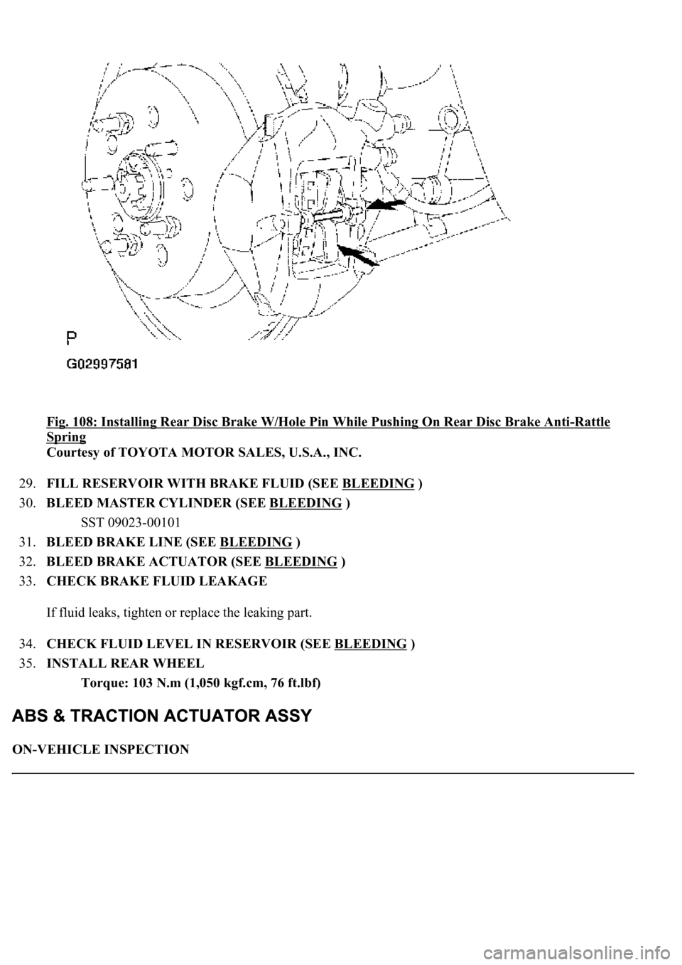
Fig. 108: Installing Rear Disc Brake W/Hole Pin While Pushing On Rear Disc Brake Anti-Rattle
Spring
Courtesy of TOYOTA MOTOR SALES, U.S.A., INC.
29.FILL RESERVOIR WITH BRAKE FLUID (SEE BLEEDING
)
30.BLEED MASTER CYLINDER (SEE BLEEDING
)
SST 09023-00101
31.BLEED BRAKE LINE (SEE BLEEDING
)
32.BLEED BRAKE ACTUATOR (SEE BLEEDING
)
33.CHECK BRAKE FLUID LEAKAGE
If fluid leaks, tighten or replace the leaking part.
34.CHECK FLUID LEVEL IN RESERVOIR (SEE BLEEDING
)
35.INSTALL REAR WHEEL
Torque: 103 N.m (1,050 kgf.cm, 76 ft.lbf)
ON-VEHICLE INSPECTION
Page 1223 of 4500
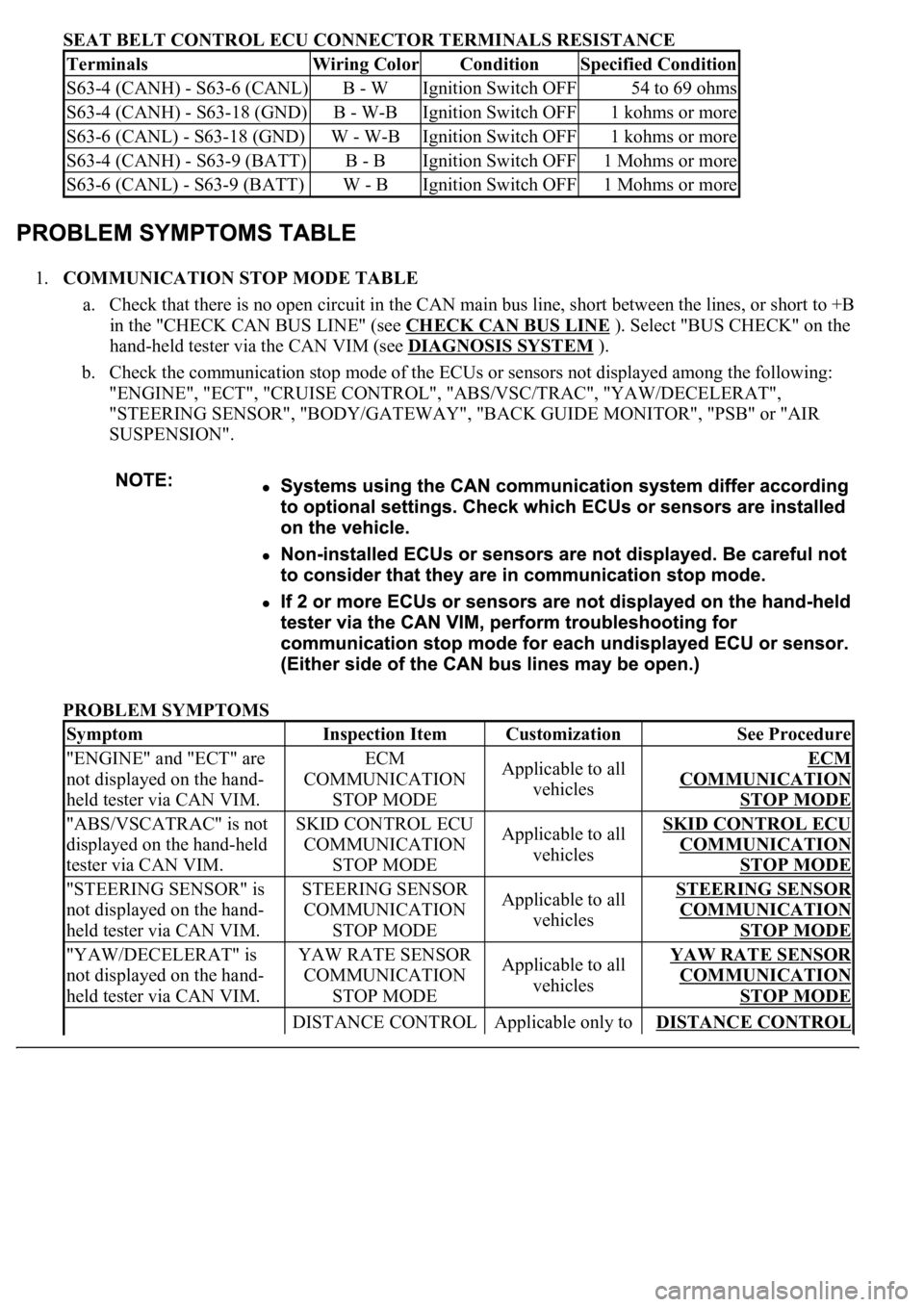
SEAT BELT CONTROL ECU CONNECTOR TERMINALS RESISTANCE
1.COMMUNICATION STOP MODE TABLE
a. Check that there is no open circuit in the CAN main bus line, short between the lines, or short to +B
in the "CHECK CAN BUS LINE" (see CHECK CAN BUS LINE
). Select "BUS CHECK" on the
hand-held tester via the CAN VIM (see DIAGNOSIS SYSTEM
).
b. Check the communication stop mode of the ECUs or sensors not displayed among the following:
"ENGINE", "ECT", "CRUISE CONTROL", "ABS/VSC/TRAC", "YAW/DECELERAT",
"STEERING SENSOR", "BODY/GATEWAY", "BACK GUIDE MONITOR", "PSB" or "AIR
SUSPENSION".
PROBLEM SYMPTOMS
TerminalsWiring ColorConditionSpecified Condition
S63-4 (CANH) - S63-6 (CANL)B - WIgnition Switch OFF54 to 69 ohms
S63-4 (CANH) - S63-18 (GND)B - W-BIgnition Switch OFF1 kohms or more
S63-6 (CANL) - S63-18 (GND)W - W-BIgnition Switch OFF1 kohms or more
S63-4 (CANH) - S63-9 (BATT)B - BIgnition Switch OFF1 Mohms or more
S63-6 (CANL) - S63-9 (BATT)W - BIgnition Switch OFF1 Mohms or more
SymptomInspection ItemCustomizationSee Procedure
"ENGINE" and "ECT" are
not displayed on the hand-
held tester via CAN VIM.ECM
COMMUNICATION
STOP MODEApplicable to all
vehiclesECM
COMMUNICATION
STOP MODE
"ABS/VSCATRAC" is not
displayed on the hand-held
tester via CAN VIM.SKID CONTROL ECU
COMMUNICATION
STOP MODEApplicable to all
vehiclesSKID CONTROL ECU
COMMUNICATION
STOP MODE
"STEERING SENSOR" is
not displayed on the hand-
held tester via CAN VIM.STEERING SENSOR
COMMUNICATION
STOP MODEApplicable to all
vehiclesSTEERING SENSOR
COMMUNICATION
STOP MODE
"YAW/DECELERAT" is
not displayed on the hand-
held tester via CAN VIM.YAW RATE SENSOR
COMMUNICATION
STOP MODEApplicable to all
vehiclesYAW RATE SENSOR
COMMUNICATION
STOP MODE
DISTANCE CONTROL Applicable only to DISTANCE CONTROL
Page 1750 of 4500
INSPECTION ).
b. Computer area
The items from "Range Over ***/Range Approx ***" to "BLANK" can be changed with the
DISP1 (switch) of the steering pad switch.
c. Graphic area
Open Door Display:
<0037004b004800030047004c00560053004f0044005c0003004c005600030056004b0052005a00510003005a004b00480051000300440051005c00030052004900030057004b00480003004700520052005500560003004400550048000300520053004800
51005600110003[
HINT:
If the warning item other than the door warning is detected at the same time, the master warning
comes on/blinks in accordance to direction from the displayed item in the warning area.
Park Sonar Display:
See HOW TO PROCEED WITH TROUBLESHOOTING for details on the park sonar display.
The display blinks when the clearance is the closest.
Others:
The items "COMPASS", "OUTSIDE TEMPERATURE" and "BLANK" can be changed with the
DISP2 (switch) of the steering pad switch.
While +B is connected, the mode that was on when the ignition switch was turned off the last time
is displayed.
When the display is changed from radar cruise, it is displayed for only 6 seconds and then returns
to the radar cruise display.
While the radar cruise is on, "RADAR CRUISE READY" is displayed in the warning area if the
park sonar and door open displays are in the graphic area.
Radar Cruise Display:
See HOW TO PROCEED WITH TROUBLESHOOTING for details on the radar cruise
display.
The radar cruise set display is interrupted for only 6 seconds while the park sonar and/or open door
(displays) are on.
<0037004b004800030047004c00560053004f0044005c000300450055004c0051004e00560003005a004b004800510003005a004400550051004c0051004a00030057004b0048000300470055004c00590048005500030057004b0044005700030057004b00
4800030047004c0056005700440051004600480003005a004c[th other vehicles is getting to be too
close. This warning has priority over all.
1.VEHICLE BROUGHT TO WORKSHOP
2.(SEE CUSTOMER PROBLEM ANALYSIS CHECK
)
3.PROBLEM SYMPTOM CONFIRMATION (SEE PROBLEM SYMPTOMS TABLE
)
4.CHECK MULTIPLEX COMMUNICATION SYSTEM (SEE HOW TO PROCEED WITH
TROUBLESHOOTING )
a. Check for DTC outputs
Page 1761 of 4500
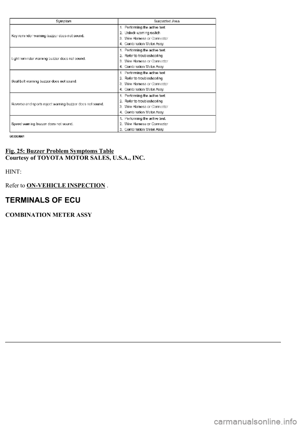
Fig. 25: Buzzer Problem Symptoms Table
Courtesy of TOYOTA MOTOR SALES, U.S.A., INC.
HINT:
Refer to ON
-VEHICLE INSPECTION .
COMBINATION METER ASSY