Page 1 of 4500
LS430 SPECIFICATIONS INDEX
SystemSpecification/Procedure
Air Conditioning
ServiceSERVICE DATA
TorqueTORQUE SPECIFICATION
Axle Nut/Hub Nut
Front69 N.m (700 kgf.cm, 51 ft.lbf)
Rear290 N.m (2,960 kgf.cm, 214 ft.lbf)
BatteryNA
Brakes
Bleeding
SequenceBLEEDING
Disc BrakesSERVICE DATA
TorqueTORQUE SPECIFICATION
Charging
GeneratorSERVICE DATA
TorqueTORQUE SPECIFICATION
Drive Belts
AdjustmentREPLACEMENT
Belt RoutingDRIVE BELT
Engine Cooling
General Service
SpecificationsSERVICE DATA
Radiator Cap
PressureStandard Value
93 to 123 kPa (0.95 to 1.25 kgf/cm
2 , 13.5 to 17.8 psi)
Minimum Standard Value
78 kPa (0.8 kgf/cm
2 , 11.4 psi)
Thermostat R & ITHERMOSTAT
Water Pump R &
IWATER PUMP
Engine Mechanical
CompressionSERVICE DATA
Oil Pressureat idle, 29 kPa (0.3 kgf.cm2 , 43 psi) or more
at 3,000 rpm, 294 to 588 kPa (3.0 to 6.0 kgf.cm
2 , 43 to 85 psi)
OverhaulSERVICE DATA
TorqueTORQUE SPECIFICATION
Page 2 of 4500
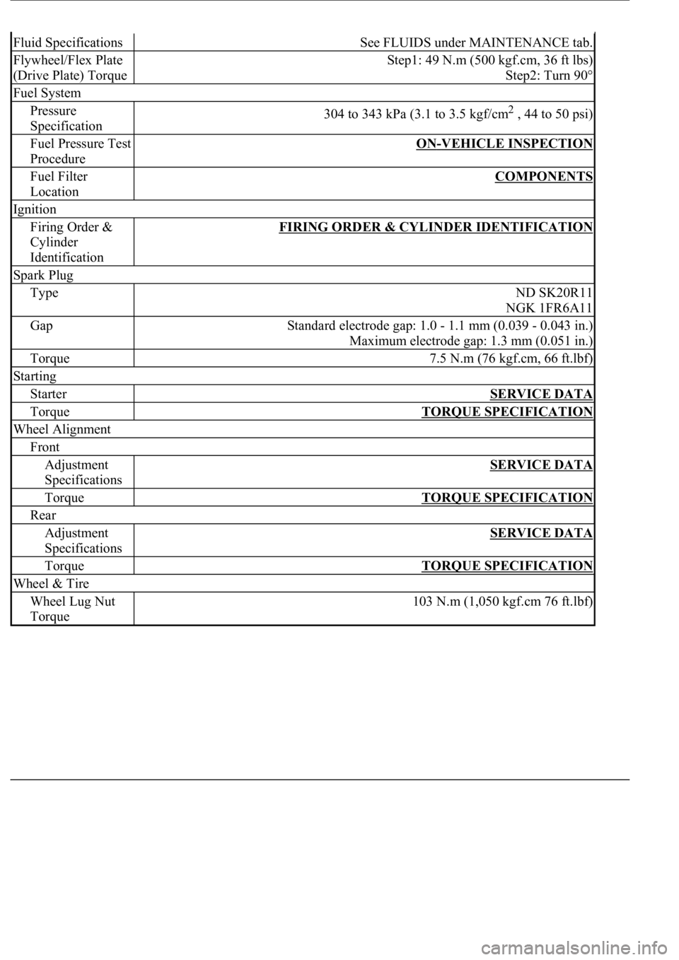
Fluid SpecificationsSee FLUIDS under MAINTENANCE tab.
Flywheel/Flex Plate
(Drive Plate) TorqueStep1: 49 N.m (500 kgf.cm, 36 ft lbs)
Step2: Turn 90°
Fuel System
Pressure
Specification304 to 343 kPa (3.1 to 3.5 kgf/cm2 , 44 to 50 psi)
Fuel Pressure Test
ProcedureON-VEHICLE INSPECTION
Fuel Filter
LocationCOMPONENTS
Ignition
Firing Order &
Cylinder
IdentificationFIRING ORDER & CYLINDER IDENTIFICATION
Spark Plug
TypeND SK20R11
NGK 1FR6A11
GapStandard electrode gap: 1.0 - 1.1 mm (0.039 - 0.043 in.)
Maximum electrode gap: 1.3 mm (0.051 in.)
Torque7.5 N.m (76 kgf.cm, 66 ft.lbf)
Starting
StarterSERVICE DATA
TorqueTORQUE SPECIFICATION
Wheel Alignment
Front
Adjustment
SpecificationsSERVICE DATA
TorqueTORQUE SPECIFICATION
Rear
Adjustment
SpecificationsSERVICE DATA
TorqueTORQUE SPECIFICATION
Wheel & Tire
Wheel Lug Nut
Torque103 N.m (1,050 kgf.cm 76 ft.lbf)
Page 878 of 4500
Courtesy of TOYOTA MOTOR SALES, U.S.A., INC.
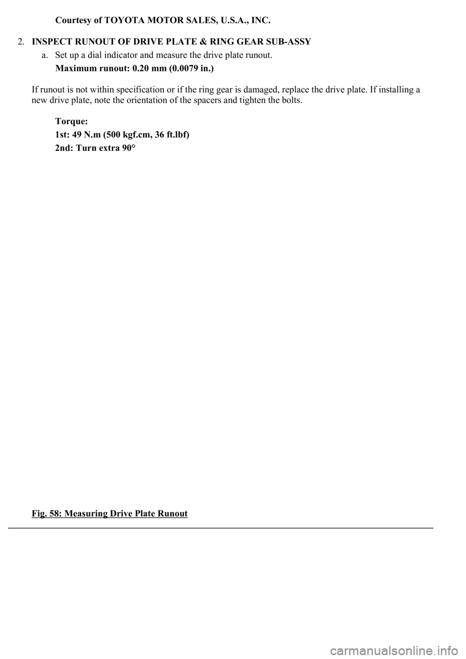
2.INSPECT RUNOUT OF DRIVE PLATE & RING GEAR SUB-ASSY
a. Set up a dial indicator and measure the drive plate runout.
Maximum runout: 0.20 mm (0.0079 in.)
If runout is not within specification or if the ring gear is damaged, replace the drive plate. If installing a
new drive plate, note the orientation of the spacers and tighten the bolts.
Torque:
1st: 49 N.m (500 kgf.cm, 36 ft.lbf)
2nd: Turn extra 90°
Fig. 58: Measuring Drive Plate Runout
Page 2061 of 4500
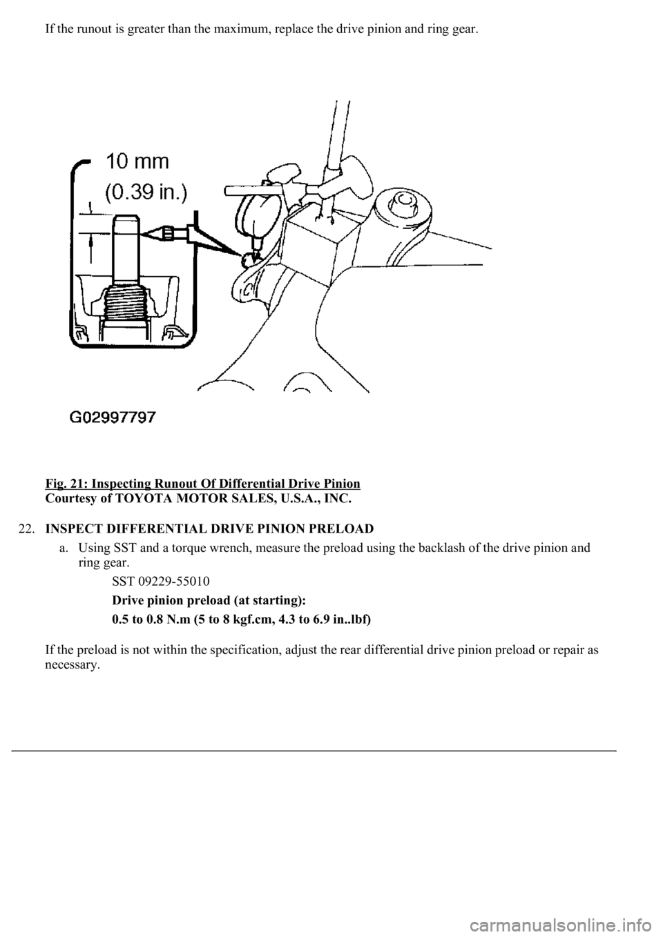
If the runout is greater than the maximum, replace the drive pinion and ring gear.
Fig. 21: Inspecting Runout Of Differential Drive Pinion
Courtesy of TOYOTA MOTOR SALES, U.S.A., INC.
22.INSPECT DIFFERENTIAL DRIVE PINION PRELOAD
a. Using SST and a torque wrench, measure the preload using the backlash of the drive pinion and
ring gear.
SST 09229-55010
Drive pinion preload (at starting):
0.5 to 0.8 N.m (5 to 8 kgf.cm, 4.3 to 6.9 in..lbf)
If the preload is not within the specification, adjust the rear differential drive pinion preload or repair as
necessar
y.
Page 2107 of 4500
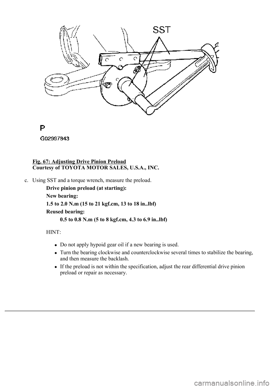
Fig. 67: Adjusting Drive Pinion Preload
Courtesy of TOYOTA MOTOR SALES, U.S.A., INC.
c. Using SST and a torque wrench, measure the preload.
Drive pinion preload (at starting):
New bearing:
1.5 to 2.0 N.m (15 to 21 kgf.cm, 13 to 18 in..lbf)
Reused bearing:
0.5 to 0.8 N.m (5 to 8 kgf.cm, 4.3 to 6.9 in..lbf)
HINT:
Do not apply hypoid gear oil if a new bearing is used.
Turn the bearing clockwise and counterclockwise several times to stabilize the bearing,
and then measure the backlash.
If the preload is not within the specification, adjust the rear differential drive pinion
preload or repair as necessar
y.
Page 2130 of 4500
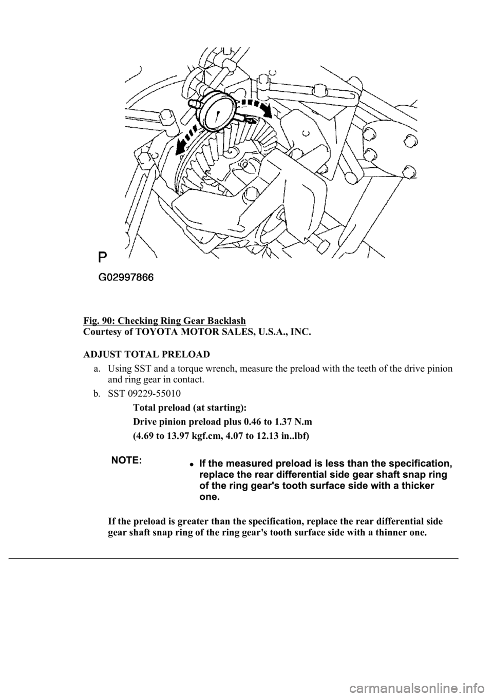
Fig. 90: Checking Ring Gear Backlash
Courtesy of TOYOTA MOTOR SALES, U.S.A., INC.
ADJUST TOTAL PRELOAD
a. Using SST and a torque wrench, measure the preload with the teeth of the drive pinion
and ring gear in contact.
b. SST 09229-55010
Total preload (at starting):
Drive pinion preload plus 0.46 to 1.37 N.m
(4.69 to 13.97 kgf.cm, 4.07 to 12.13 in..lbf)
If the preload is greater than the specification, replace the rear differential side
gear shaft snap ring of the ring gear's tooth surface side with a thinner one.
Page 2350 of 4500
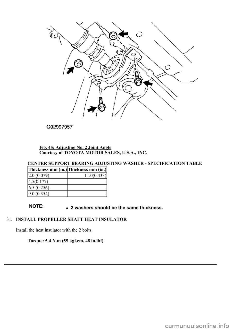
Fig. 45: Adjusting No. 2 Joint Angle
Courtesy of TOYOTA MOTOR SALES, U.S.A., INC.
CENTER SUPPORT BEARING ADJUSTING WASHER - SPECIFICATION TABLE
31.INSTALL PROPELLER SHAFT HEAT INSULATOR
Install the heat insulator with the 2 bolts.
Torque: 5.4 N.m (55 kgf.cm, 48 in.lbf)
Thickness mm (in.)Thickness mm (in.)
2.0 (0.079)11.0(0.433)
4.5(0.177)-
6.5 (0.256)-
9.0 (0.354)-
Page 2871 of 4500
relay valve and locks the torque converter clutch.
If the ECM detects no lock-up after lock-up has been requested or if it detects lock-up when it is not requested,
the ECM interprets this as a fault in the shift solenoid valve SLU or lock-up system performance.
The ECM will turn on the MIL and store the DTC.
Example:
When any of the following is met, the system judges it as a malfunction.
a. There is a difference in rotation between before and after torque converters even when the ECM
commands lock-up.
(Engine speed is at least 75 rpm greater than input turbine speed.)
b. There is no difference in rotation between before and after torque converters even when the ECM
commands lock-up off.
(The difference between engine speed and input turbine speed is less than 35 rpm.)
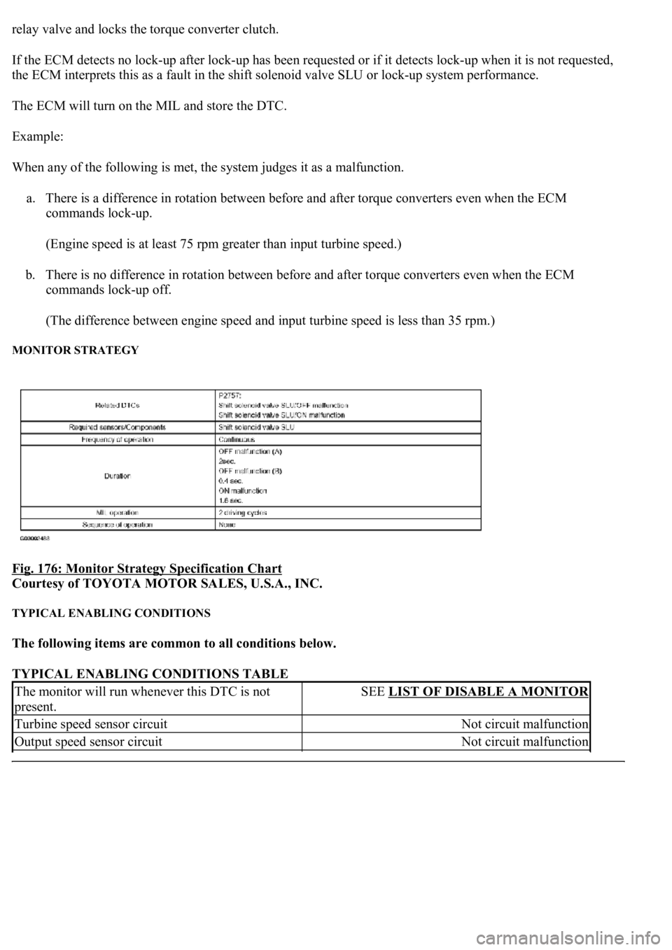
MONITOR STRATEGY
Fig. 176: Monitor Strategy Specification Chart
Courtesy of TOYOTA MOTOR SALES, U.S.A., INC.
TYPICAL ENABLING CONDITIONS
The following items are common to all conditions below.
TYPICAL ENABLING CONDITIONS TABLE
The monitor will run whenever this DTC is not
present.SEE LIST OF DISABLE A MONITOR
Turbine speed sensor circuitNot circuit malfunction
Output speed sensor circuitNot circuit malfunction