Page 301 of 4500
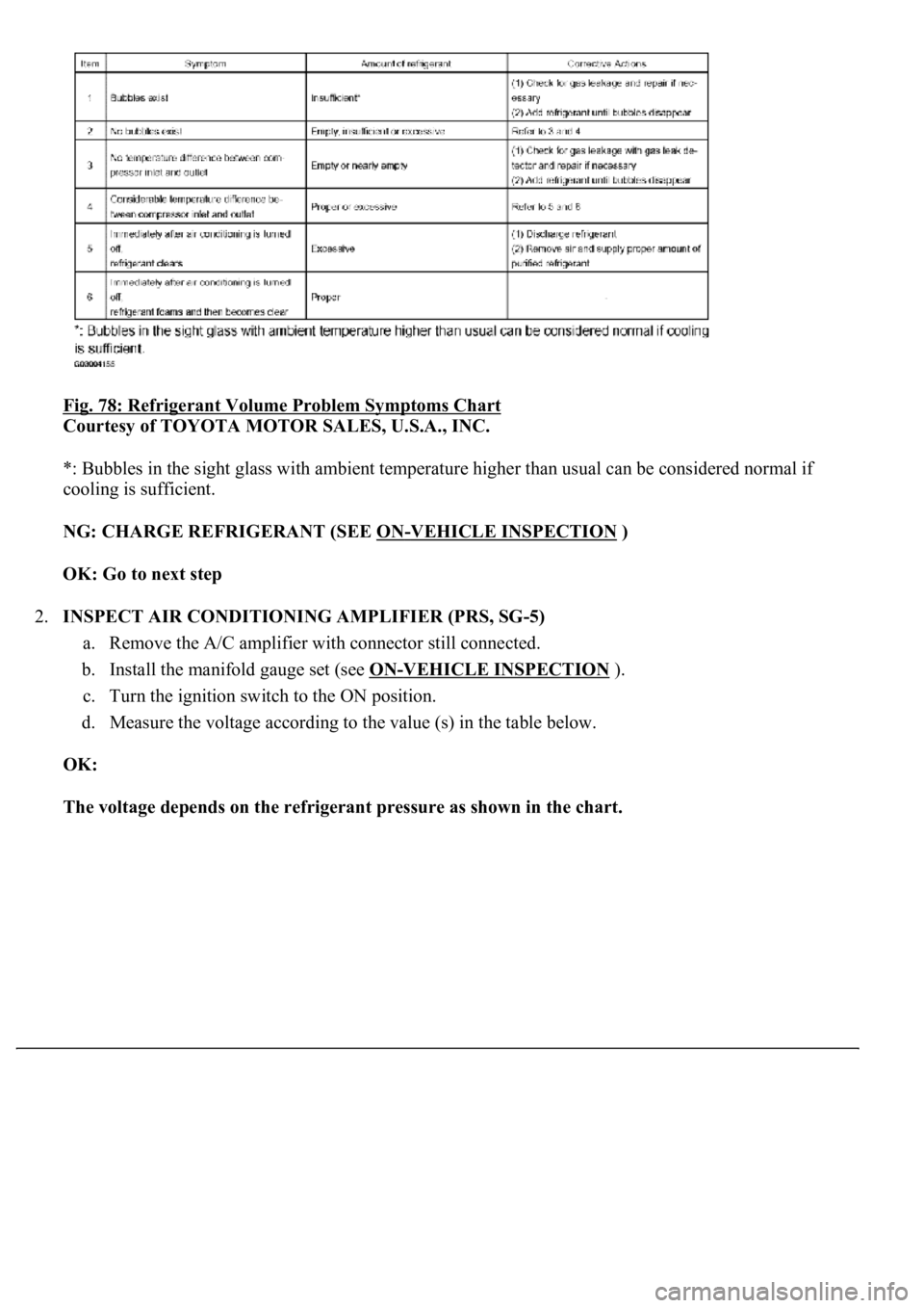
Fig. 78: Refrigerant Volume Problem Symptoms Chart
Courtesy of TOYOTA MOTOR SALES, U.S.A., INC.
*: Bubbles in the sight glass with ambient temperature higher than usual can be considered normal if
cooling is sufficient.
NG: CHARGE REFRIGERANT (SEE ON
-VEHICLE INSPECTION )
OK: Go to next step
2.INSPECT AIR CONDITIONING AMPLIFIER (PRS, SG-5)
a. Remove the A/C amplifier with connector still connected.
b. Install the manifold gauge set (see ON
-VEHICLE INSPECTION ).
c. Turn the ignition switch to the ON position.
d. Measure the voltage according to the value (s) in the table below.
OK:
The voltage depends on the refrigerant pressure as shown in the chart.
Page 303 of 4500
Courtesy of TOYOTA MOTOR SALES, U.S.A., INC.
NG: Go to STEP 3
OK: PROCEED TO NEXT CIRCUIT INSPECTION SHOWN IN PROBLEM SYMPTOMS
TABLE
3.INSPECT A/C PRESSURE SENSOR
a. Disconnect the A/C pressure sensor connector.
b. Install the manifold gauge set (see ON
-VEHICLE INSPECTION ).
c. Connect the positive (+) lead from the three 1.5 V dry cell batteries to terminal 3 and negative (-)
lead to terminal1.
d. Check voltage between terminals 2 and 1 of A/C pressure sensor.
OK:
The voltage depends on the refrigerant pressure as shown in the chart.
Page 499 of 4500

Proceed to troubleshooting following the flow chart, regardless of whether or not DTC C1711, C1712, C1713
or C1714 is displayed.
1.RECONFIRM DTC
a. Check DTCs (SEE DTC CHECK/CLEAR
).
1. Confirm if DTC C1761 and/or C1774 is recorded.
OK:
DTC C1761 and/or C1774 is not output.
HINT:
If either DTC C1761 (ECU malfunction) (SEE DTC C1761 ECU MALFUNCTION
or DTC C1774
POWER SOURCE CIRCUIT ) is displayed, carry out the necessary inspection. If they are output at the
same time, carry out the necessary inspection for DTC C1774 first.
NG: REPAIR CIRCUIT INDICATED BY OUTPUT CODE
OK:Go to next step
2.READ VALUE ON HAND-HELD TESTER
a. Connect the hand-held tester to the DLC3.
b. Turn the ignition switch to the ON position and turn the hand-held tester main switch on.
c. Select the item below in the DATA LIST and read its value displayed on the hand-held tester.
AIRSUS:
Fig. 21: Air sus
- Data List
Courtesy of TOYOTA MOTOR SALES, U.S.A., INC.
d. Check the vehicle height value of each sensor while pressing the height control switch "UP" and
"DOWN".
OK:
Vehicle height value changes.
Page 526 of 4500
Fig. 48: Rear Acceleration Sensor Wiring Diagram
Courtesy of TOYOTA MOTOR SALES, U.S.A., INC.
INSPECTION PROCEDURE
1.READ VALUE ON HAND-HELD TESTER
a. Connect the hand-held tester to the DLC3.
b. Turn the ignition switch to the ON position and turn the hand-held tester main switch on.
c. Select the item below in the DATA LIST and read its value displayed on the hand-held tester.
DATA LIST AIR SUS
d. Check that the acceleration value of the acceleration sensor observed on the hand-held tester
changes when the vehicle is bounced.
Standard:
ItemNormal condition
G (UP & DOWN) FR (Right front acceleration sensor)0 +/- 31.9 mm/s2 at still condition
G (UP & DOWN) FL (Left front acceleration sensor)0 +/- 31.9 mm/s2 at still condition
G (UP & DOWN) R (Rear acceleration sensor)0 +/- 31.9 mm/s2 at still condition
Page 557 of 4500
POWER SOURCE CIRCUIT ) is displayed, carry out the necessary inspection. If they are output at the
same time, carry out the necessary inspection for DTC C1774 first.
NG: REPAIR CIRCUIT INDICATED BY OUTPUT CODE
OK:Go to next step
2.PERFORM ACTIVE TEST BY HAND-HELD TESTER
a. Connect the hand-held tester to the DLC3.
b. Turn the ignition switch to the ON position and turn the hand-held tester main switch on.
c. Select the item below in the ACTIVE TEST and operate it with the hand-held tester.
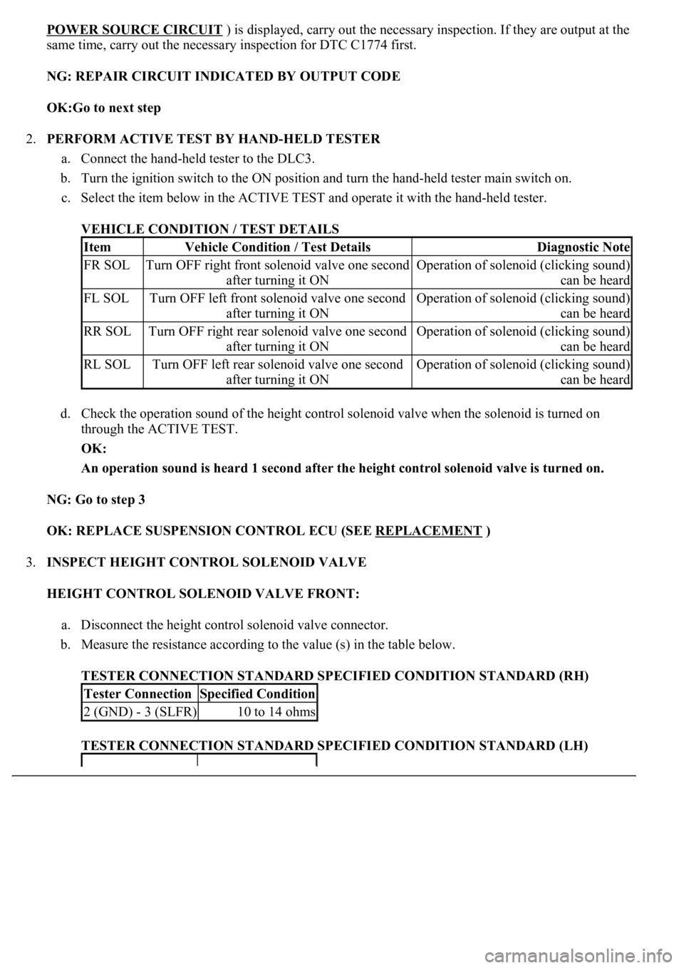
VEHICLE CONDITION / TEST DETAILS
d. Check the operation sound of the height control solenoid valve when the solenoid is turned on
through the ACTIVE TEST.
OK:
An operation sound is heard 1 second after the height control solenoid valve is turned on.
NG: Go to step 3
OK: REPLACE SUSPENSION CONTROL ECU (SEE REPLACEMENT
)
3.INSPECT HEIGHT CONTROL SOLENOID VALVE
HEIGHT CONTROL SOLENOID VALVE FRONT:
a. Disconnect the height control solenoid valve connector.
b. Measure the resistance according to the value (s) in the table below.
TESTER CONNECTION STANDARD SPECIFIED CONDITION STANDARD (RH)
TESTER CONNECTION STANDARD SPECIFIED CONDITION STANDARD (LH)
ItemVehicle Condition / Test DetailsDiagnostic Note
FR SOLTurn OFF right front solenoid valve one second
after turning it ONOperation of solenoid (clicking sound)
can be heard
FL SOLTurn OFF left front solenoid valve one second
after turning it ONOperation of solenoid (clicking sound)
can be heard
RR SOLTurn OFF right rear solenoid valve one second
after turning it ONOperation of solenoid (clicking sound)
can be heard
RL SOLTurn OFF left rear solenoid valve one second
after turning it ONOperation of solenoid (clicking sound)
can be heard
Tester ConnectionSpecified Condition
2 (GND) - 3 (SLFR)10 to 14 ohms
Page 568 of 4500
POWER SOURCE CIRCUIT ) is displayed, carry out the necessary inspection. If they are output at the
same time, carry out the necessary inspection for DTC C1774 first.
NG: REPAIR CIRCUIT INDICATED BY OUTPUT CODE
OK:Go to next step
2.PERFORM ACTIVE TEST BY HAND-HELD TESTER
a. Connect the hand-held tester to the DLC3.
b. Turn the ignition switch to the ON position and turn the hand-held tester main switch on.
c. Select the item below in the ACTIVE TEST and operate it with the hand-held tester.
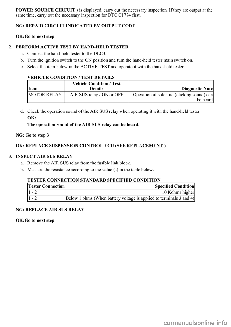
VEHICLE CONDITION / TEST DETAILS
d. Check the operation sound of the AIR SUS relay when operating it with the hand-held tester.
OK:
The operation sound of the AIR SUS relay can be heard.
NG: Go to step 3
OK: REPLACE SUSPENSION CONTROL ECU (SEE REPLACEMENT
)
3.INSPECT AIR SUS RELAY
a. Remove the AIR SUS relay from the fusible link block.
b. Measure the resistance according to the value (s) in the table below.
TESTER CONNECTION STANDARD SPECIFIED CONDITION
NG: REPLACE AIR SUS RELAY
OK:Go to next step
Item
Vehicle Condition / Test
Details
Diagnostic Note
MOTOR RELAYAIR SUS relay / ON or OFFOperation of solenoid (clicking sound) can
be heard
Tester ConnectionSpecified Condition
1 - 210 Kohms higher
1 - 2Below 1 ohms (When battery voltage is applied to terminals 3 and 4)
Page 587 of 4500
10.INSPECT FOR CLOGGED AIR TUBE
a. Check the air tube visually for a clog or damage (see ON
-VEHICLE INSPECTION ).
OK:
Air tube is not clogged or damaged.
NG: REPAIR OR REPLACE AIR TUBE
OK: REPLACE SUSPENSION CONTROL ECU (SEE REPLACEMENT
)
CIRCUIT DESCRIPTION
The signal from the suspension control ECU operates the AIR SUS relay and the height control compressor
motor starts.
The height control compressor motor operates until the targeted vehicle height is reached. Then the height
control sensor sub-assy sends the signal to the suspension control ECU, and stops the height control compressor
motor.
Fig. 104: DTC C1751 And DTC C1752 Detecting Condition And Trouble Area
Courtesy of TOYOTA MOTOR SALES, U.S.A., INC.
INSPECTION PROCEDURE
1.CHECK HEIGHT CONTROL COMPRESSOR CIRCUIT (SEE DTC C1742 HEIGHT
CONTROL COMPRESSOR CIRCUIT )
2.CHECK AIR LEAKAGE (SEE ON
-VEHICLE INSPECTION )
OK:
No leaks
Page 593 of 4500

c. Check the operating sound of the exhaust solenoid valve.
OK:
It should make an operating sound (click).
HINT:
When a malfunction is found in the exhaust solenoid valve, replace the height control compressor assy.
NG: REPLACE HEIGHT CONTROL COMPRESSOR ASSY (SEE REPLACEMENT
)
OK:Go to next step
6.INSPECT HEIGHT CONTROL SENSOR LINK SUB-ASSY
a. Inspect and adjust the height control sensor link sub-assy (see ON
-VEHICLE INSPECTION ).
NG: REPLACE HEIGHT CONTROL SENSOR LINK SUB-ASSY
OK: CHECK AND REPAIR OR REPLACE PARTS
Air tube is clogged (see ON-VEHICLE INSPECTION ).
Compressor is faulty (see REPLACEMENT ).
Height control sensor sub-assy is faulty (see REPLACEMENT - HEIGHT CONTROL
SENSOR SUB-ASSY FRONT , REPLACEMENT - HEIGHT CONTROL SENSOR SUB-
ASSY REAR LH ).
Foreign material in the height control solenoid valve and/or exhaust solenoid valve (see
REPLACEMENT
- HEIGHT CONTROL COMPRESSOR ASSY , REPLACEMENT -
HEIGHT CONTROL VALVE SUB
-ASSY NO.1 , REPLACEMENT - HEIGHT CONTROL
VALVE SUB-ASSY NO.2 ).
Suspension control ECU malfunction (see REPLACEMENT ).
CIRCUIT DESCRIPTION