Page 2600 of 4500
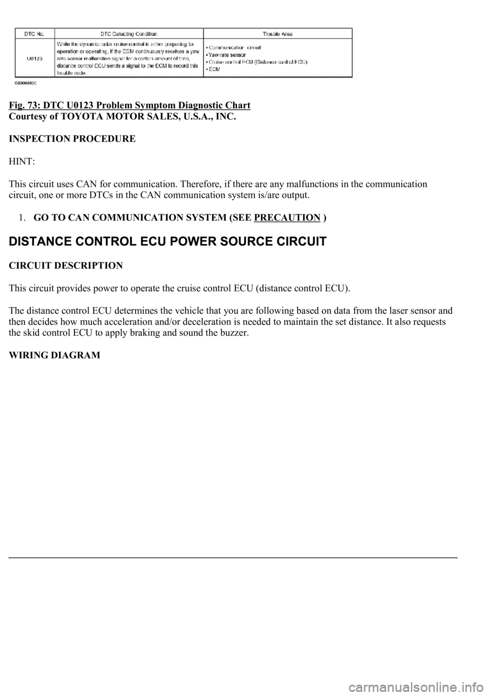
Fig. 73: DTC U0123 Problem Symptom Diagnostic Chart
Courtesy of TOYOTA MOTOR SALES, U.S.A., INC.
INSPECTION PROCEDURE
HINT:
This circuit uses CAN for communication. Therefore, if there are any malfunctions in the communication
circuit, one or more DTCs in the CAN communication system is/are output.
1.GO TO CAN COMMUNICATION SYSTEM (SEE PRECAUTION
)
CIRCUIT DESCRIPTION
<0037004b004c005600030046004c005500460058004c005700030053005500520059004c004700480056000300530052005a004800550003005700520003005200530048005500440057004800030057004b00480003004600550058004c00560048000300
4600520051005700550052004f00030028002600380003000b[distance control ECU).
The distance control ECU determines the vehicle that you are following based on data from the laser sensor and
then decides how much acceleration and/or deceleration is needed to maintain the set distance. It also requests
the skid control ECU to apply braking and sound the buzzer.
WIRING DIAGRAM
Page 2611 of 4500
The dynamic laser cruise control system has two cruise control modes: the constant speed control mode and
vehicle-to-vehicle distance control mode.
The vehicle-to-vehicle distance control mode is always selected when starting up the dynamic radar
cruise control system.
The operation of the constant speed control mode is the same as that for the conventional type cruise
control system.
WIRING DIAGRAM
Fig. 82: Wiring Diagram
- Cruise Control Switch Circuit
Courtesy of TOYOTA MOTOR SALES, U.S.A., INC.
INSPECTION PROCEDURE
1.READ VALUE OF HAND-HELD TESTER
a. Connect the hand-held tester to the DLC3.
b. Turn the ignition switch to the ON position.
c. Accordin
g to the display on the tester, read the "DATA LIST".
Page 2619 of 4500
Courtesy of TOYOTA MOTOR SALES, U.S.A., INC.
OK: REPLACE ECM (SEE REPLACEMENT
)
CIRCUIT DESCRIPTION
The distance control switch sets the vehicle-to-vehicle distance mode.
The distance control switch (DISP2 button) is installed in the steering pad switch modulator. The vehicle-to-
vehicle distance set value can be changed by operating the distance control switch (DISP2 button) while the
dynamic radar cruise control system is in operation.
The steering pad switch modulator uses BEAN to communicate with each ECU. Therefore it does not have a
direct connection with the ECM. If there are any malfunctions in the communication line of the steering pad
switch modulator, one or more DTCs in the multiplex communication system is/are output.
INSPECTION PROCEDURE
1.READ VALUE ON HAND-HELD TESTER
a. Connect the hand-held tester to the DLC3.
b. Turn the ignition switch to the ON position.
c. Select the item "DISP2 (MULTI MODE SW)" in the DATA LIST, and read its value on the hand-
held tester.
d. Check the indication displayed on the hand-held tester, when the steering pad switch (DISP2) is
ON and when it is OFF.
MULTI-INFORMATION DISPLAY CONTROL SWITCH (STEERING PAD SWITCH
MODULATOR):
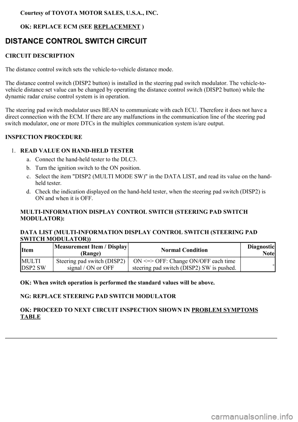
DATA LIST (MULTI-INFORMATION DISPLAY CONTROL SWITCH (STEERING PAD
SWITCH MODULATOR))
OK: When switch operation is performed the standard values will be above.
NG: REPLACE STEERING PAD SWITCH MODULATOR
OK: PROCEED TO NEXT CIRCUIT INSPECTION SHOWN IN PROBLEM SYMPTOMS
TABLE
ItemMeasurement Item / Display
(Range)Normal ConditionDiagnostic
Note
MULTI
DSP2 SWSteering pad switch (DISP2)
signal / ON or OFFON <=> OFF: Change ON/OFF each time
steering pad switch (DISP2) SW is pushed.-
Page 2620 of 4500
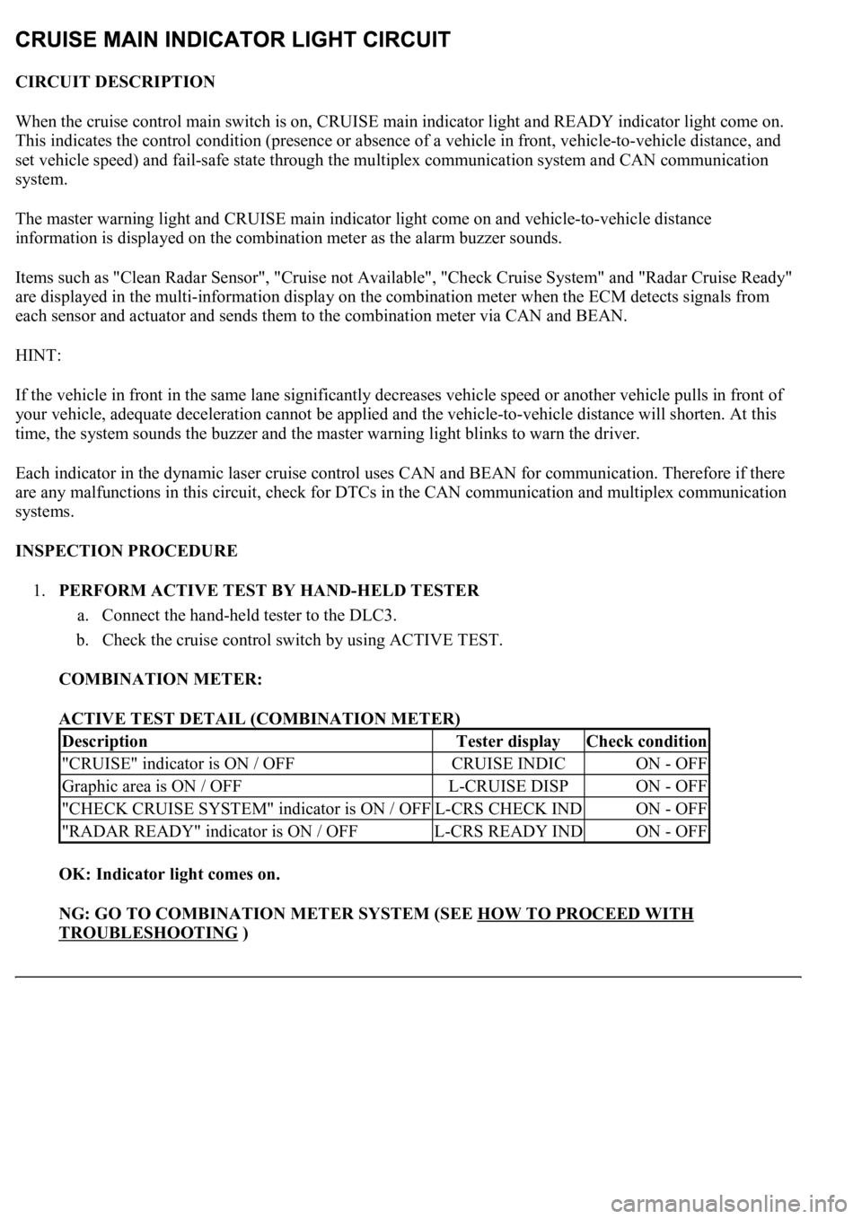
CIRCUIT DESCRIPTION
When the cruise control main switch is on, CRUISE main indicator light and READY indicator light come on.
This indicates the control condition (presence or absence of a vehicle in front, vehicle-to-vehicle distance, and
set vehicle speed) and fail-safe state through the multiplex communication system and CAN communication
system.
The master warning light and CRUISE main indicator light come on and vehicle-to-vehicle distance
information is displayed on the combination meter as the alarm buzzer sounds.
Items such as "Clean Radar Sensor", "Cruise not Available", "Check Cruise System" and "Radar Cruise Ready"
are displayed in the multi-information display on the combination meter when the ECM detects signals from
each sensor and actuator and sends them to the combination meter via CAN and BEAN.
HINT:
If the vehicle in front in the same lane significantly decreases vehicle speed or another vehicle pulls in front of
your vehicle, adequate deceleration cannot be applied and the vehicle-to-vehicle distance will shorten. At this
time, the system sounds the buzzer and the master warning light blinks to warn the driver.
Each indicator in the dynamic laser cruise control uses CAN and BEAN for communication. Therefore if there
are any malfunctions in this circuit, check for DTCs in the CAN communication and multiplex communication
systems.
INSPECTION PROCEDURE
1.PERFORM ACTIVE TEST BY HAND-HELD TESTER
a. Connect the hand-held tester to the DLC3.
b. Check the cruise control switch by using ACTIVE TEST.
COMBINATION METER:
ACTIVE TEST DETAIL (COMBINATION METER)
OK: Indicator light comes on.
NG: GO TO COMBINATION METER SYSTEM (SEE HOW TO PROCEED WITH
TROUBLESHOOTING )
DescriptionTester displayCheck condition
"CRUISE" indicator is ON / OFFCRUISE INDICON - OFF
Graphic area is ON / OFFL-CRUISE DISPON - OFF
"CHECK CRUISE SYSTEM" indicator is ON / OFFL-CRS CHECK INDON - OFF
"RADAR READY" indicator is ON / OFFL-CRS READY INDON - OFF
Page 2676 of 4500
SYSTEM DESCRIPTION
1.SYSTEM DESCRIPTION
a. The ECT (Electronic controlled automatic transmission) is an automatic transmission that
electronically controls shift timing using the ECM. The ECM detects electrical signals that indicate
engine and driving conditions, and controls the shift point, based on driver habits and road
conditions. As a result, fuel efficiency and power transmission performance are improved.
<0036004b004c0049005700030056004b00520046004e0003004b00440056000300450048004800510003005500480047005800460048004700030045005c0003004600520051005700550052004f004f004c0051004a00030057004b004800030048005100
4a004c00510048000300440051004700030057005500440051[smission simultaneously. In
addition, the ECT has features such as follows:
Diagnostic function.
Fail-safe function when a malfunction occurs.
HOW TO PROCEED WITH TROUBLESHOOTING
HINT:
The ECM of this system is connected to the CAN and multiplex communication system. Therefore,
before starting troubleshooting, make sure to check that there is no trouble in the CAN and multiplex
communication system.
<0037004b00480003004b0044005100470010004b0048004f0047000300570048005600570048005500030046004400510003004500480003005800560048004700030044005700030056005700480053005600030016000f00030017000f00030019000f00
030044005100470003001c00110003[
1.Vehicle Brought to Workshop
2.Customer Problem Analysis (See CUSTOMER PROBLEM ANALYSIS CHECK
)
3.Connect the OBD II scan tool or hand-held tester to DLC3
4.Check and Clear DTCs and Freeze Frame Data (See DTC CHECK/CLEAR
)
5.Visual Inspection
6.Setting the Check Mode Diagnosis (See CHECK MODE PROCEDURE
)
7.Problem Symptom Confirmation (See ROAD TEST
)
Symptom does not occur: Go to step 8
Symptom occurs: Go to step 9
8.Symptom Simulation (See HOW TO PROCEED WITH TROUBLESHOOTING
)
9.DTC Check (See DTC CHECK/CLEAR
)
DTC is not output: Go to step 10
DTC is output: Go to step 17
10.Basic Inspection (See ADJUSTMENT
- AUTOMATIC TRANSMISSION FLUID ,
ADJUSTMENT
- PARK/NEUTRAL POSITION SWITCH ASSY and ADJUSTMENT -
FLOOR SHIFT ASSY
)
Page 2696 of 4500
Fig. 19: Identifying Vehicle Speed Pattern
Courtesy of TOYOTA MOTOR SALES, U.S.A., INC.
HINT:
*1: Drive at such a speed in the uppermost gear, to engage lock-up. The vehicle can be driven at a speed
lower than that in the above diagram under the lock-up condition.
PROBLEM SYMPTOMS TABLE
HINT:
If a normal code is displayed during the diagnostic trouble code check although the trouble still occurs, check
the electrical circuits for each symptom in the order given in the following charts.
The Matrix Chart is divided into 2 chapters.
1.Chapter 1: Electronic Circuit Matrix Chart
Refer to the table below when the trouble cause is considered to be electrical.
If the instruction "Proceed to next circuit inspection shown on matrix chart" is given in the flow
chart of each circuit, proceed to the circuit with the next highest number in the table to continue the
check.
Page 2744 of 4500
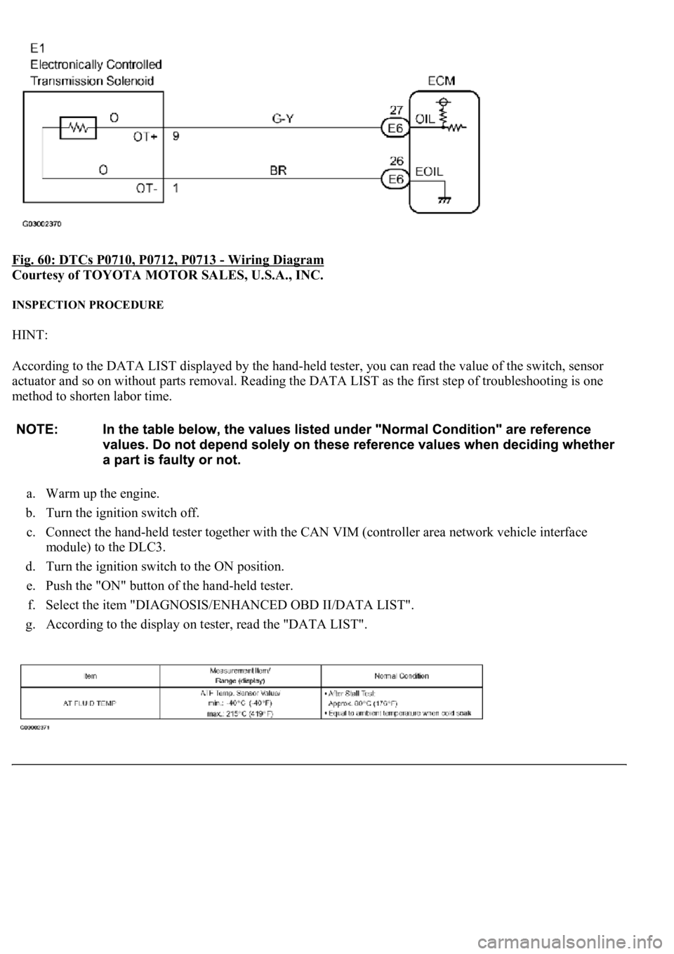
Fig. 60: DTCs P0710, P0712, P0713 - Wiring Diagram
Courtesy of TOYOTA MOTOR SALES, U.S.A., INC.
INSPECTION PROCEDURE
HINT:
According to the DATA LIST displayed by the hand-held tester, you can read the value of the switch, sensor
actuator and so on without parts removal. Reading the DATA LIST as the first step of troubleshooting is one
method to shorten labor time.
a. Warm up the engine.
b. Turn the ignition switch off.
c. Connect the hand-held tester together with the CAN VIM (controller area network vehicle interface
module) to the DLC3.
d. Turn the ignition switch to the ON position.
e. Push the "ON" button of the hand-held tester.
f. Select the item "DIAGNOSIS/ENHANCED OBD II/DATA LIST".
g. According to the display on tester, read the "DATA LIST".
Page 2748 of 4500
Courtesy of TOYOTA MOTOR SALES, U.S.A., INC.
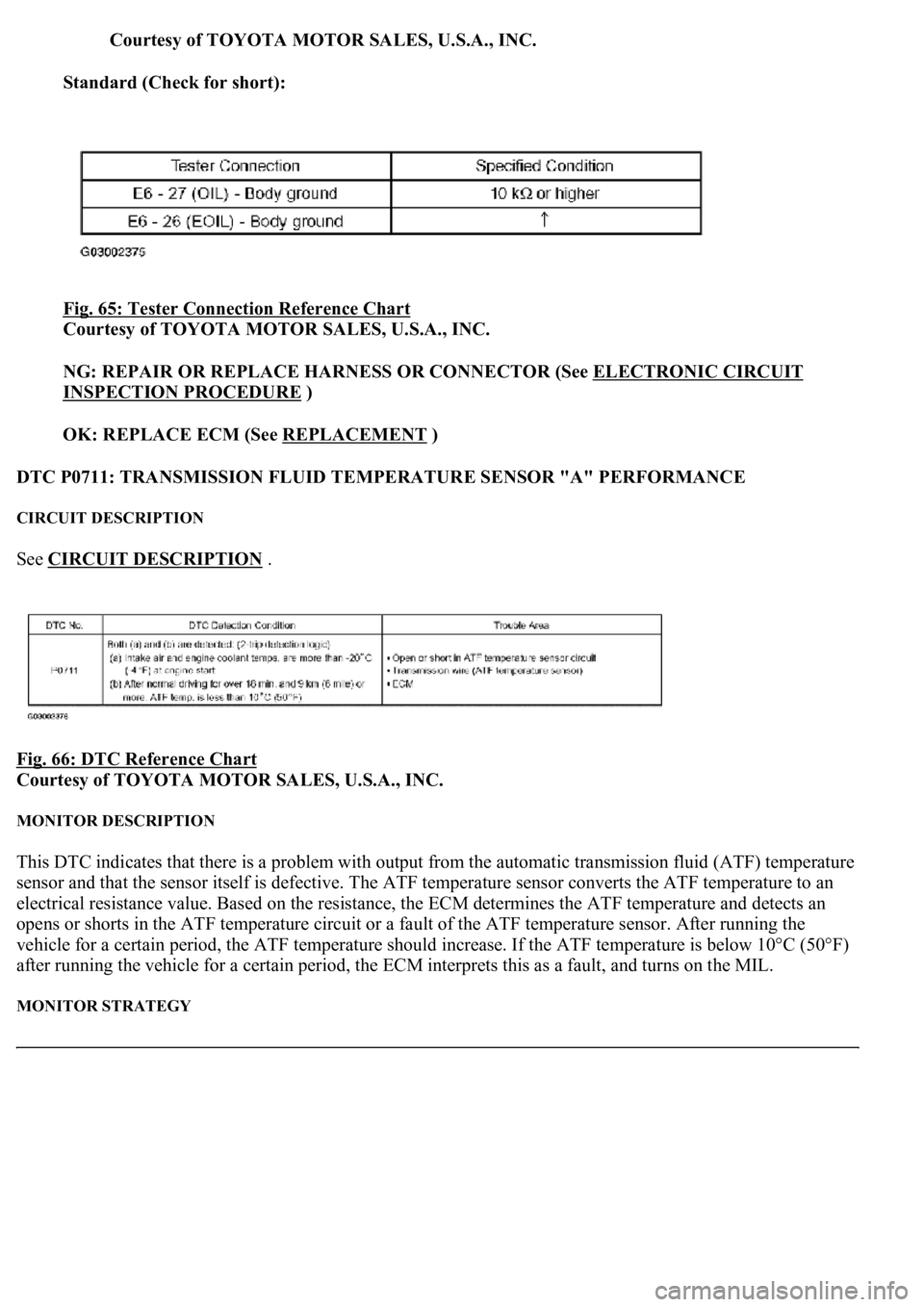
Standard (Check for short):
Fig. 65: Tester Connection Reference Chart
Courtesy of TOYOTA MOTOR SALES, U.S.A., INC.
NG: REPAIR OR REPLACE HARNESS OR CONNECTOR (See ELECTRONIC CIRCUIT
INSPECTION PROCEDURE )
OK: REPLACE ECM (See REPLACEMENT
)
DTC P0711: TRANSMISSION FLUID TEMPERATURE SENSOR "A" PERFORMANCE
CIRCUIT DESCRIPTION
See CIRCUIT DESCRIPTION .
Fig. 66: DTC Reference Chart
Courtesy of TOYOTA MOTOR SALES, U.S.A., INC.
MONITOR DESCRIPTION
This DTC indicates that there is a problem with output from the automatic transmission fluid (ATF) temperature
sensor and that the sensor itself is defective. The ATF temperature sensor converts the ATF temperature to an
electrical resistance value. Based on the resistance, the ECM determines the ATF temperature and detects an
opens or shorts in the ATF temperature circuit or a fault of the ATF temperature sensor. After running the
vehicle for a certain period, the ATF temperature should increase. If the ATF temperature is below 10°C (50°F)
after running the vehicle for a certain period, the ECM interprets this as a fault, and turns on the MIL.
MONITOR STRATEGY