Page 931 of 4500
Fig. 106: Removing 4 Bolts
Courtesy of TOYOTA MOTOR SALES, U.S.A., INC.
23.REMOVE INDOOR ELECTRICALLY KEY OSCILLATOR (W/SMART KEY)
a. Remove the 2 screws, and then remove the indoor electrical key oscillator from the shift lever plate.
24.REMOVE SHIFT LOCK RELEASE BUTTON COVER
a. Using a small screwdriver, remove the shift lock release button cover.
25.REMOVE SHIFT LEVER KNOB SUB-ASSY
a. Remove the shift lever knob sub-assy.
Page 980 of 4500

3.REMOVE SEAT TRACK COVER LH
4.REMOVE SEAT TRACK BRACKET COVER OUTER FR
5.REMOVE SEAT TRACK BRACKET COVER INNER FR
6.REMOVE FRONT SEAT ASSY LH
7.REMOVE INSTRUMENT CLUSTER FINISH PANEL END
8.REMOVE INSTRUMENT CLUSTER FINISH PANEL CENTER LOWER
9.REMOVE INSTRUMENT PANEL UNDER COVER SUB-ASSY NO.1 (SEE REPLACEMENT
)
10.REMOVE COIN BOX ASSY
11.REMOVE OUTER MIRROR SWITCH ASSY
12.REMOVE INSTRUMENT PANEL SAFETY PAD SUB-ASSY NO.1 (SEE REPLACEMENT
)
13.REMOVE INSTRUMENT PANEL UNDER COVER SUB-ASSY No.2 (SEE REPLACEMENT
)
14.REMOVE FR DOOR SCUFF PLATE LH (SEE REPLACEMENT
)
15.REMOVE FLOOR CARPET ASSY FRONT
16.CHECK AND ADJUST BRAKE PEDAL HEIGHT
a. Check brake pedal height.
Pedal height from asphalt sheet:
165.1 to 175.1 mm (6.49 to 6.89 in.)
b. If necessary, adjust brake pedal height.
1. Disconnect the connector from the stop lamp switch assy.
2. Loosen the stop lamp switch lock nut and remove the stop lamp switch assy.
3. Loosen the push rod lock nut.
4. Adjust the pedal height by turning the pedal push rod.
5. Tighten the push rod lock nut.
Torque: 26 N.m (265 kgf.cm, 19 ft.lbf)
6. Install the stop lamp switch assy.
7. Connect the stop lamp switch assy connector.
8. Push the brake pedal in 5 to 10 mm (0.20 to 0.39 in.), and turn the stop lamp switch assy to lock the
<0051005800570003004c005100030057004b00480003005300520056004c0057004c005200510003005a004b00480055004800030057004b0048000300560057005200530003004f0044005000530003004a00520048005600030052004900490011000300
03[
9. After installation, push the brake pedal in 5 to 10 mm (0.20 to 0.39 in.), and check that the stop
lamp comes on.
10. Tighten the stop lamp switch lock nut.
Torque: 17 N.m (173 kgf.cm, 12 ft.lbf)
If the stop lamp does not come on, repeat the steps in (
b).
Page 1144 of 4500
57.INSTALL PANEL INSTRUMENT CLUSTER FINISH LOWER (SEE REPLACEMENT )
58.INSTALL INSTRUMENT PANEL FINISH PANEL LOWER CENTER (SEE REPLACEMENT
)
59.INSTALL FRONT DOOR SCUFF PLATE LH (SEE REPLACEMENT
)
60.INSTALL INSTRUMENT PANEL FINISH PANEL (SEE REPLACEMENT
)
61.INSTALL CHOKE KNOB HOLE COVER (SEE REPLACEMENT
)
62.INSTALL GLOVE COMPARTMENT PLATE (SEE REPLACEMENT
)
63.INSTALL INSTRUMENT PANEL GARNISH SUB-ASSY LH (SEE REPLACEMENT
)
64.INSTALL FRONT SEAT ASSY LH (SEE OVERHAUL
)
65.INSTALL SEAT TRACK BRACKET COVER INNER FRONT
66.INSTALL SEAT TRACK BRACKET COVER OUTER FRONT
67.INSTALL SEAT TRACK OUTER COVER LH
68.INSTALL SEAT TRACK COVER RH
69.INSTALL SEAT BELT ANCHOR COVER CAP LH
70.REMOVE REAR WHEEL
71.ADJUST PARKING BRAKE SHOE CLEARANCE
a. Remove the hole plug.
b. Turn the adjuster and expand the shoes until the disc locks.
c. Return the adjuster 7 notches. Install the hole plug.
Page 2181 of 4500

1.GENERAL
When the front and rear door system detects that the front and rear doors are ajar, it automatically
actuates the motor to fully close the front and rear doors.
Position detection switches are provided in the door closer mechanism in each of the front and rear
doors' lock assemblies to detect whether the front and rear doors are open, closed or ajar. If a
detection signal that indicates that a front or rear door is ajar is transmitted to the door ECU, the
door ECU actuates the door closer motor to fully close the door.
In this system, each door is independently controlled by the door ECU inside each door. The door
ECUs, which communicate via the BEAN, belong to the door bus.
A mechanical cancel mechanism is provided. This mechanism enables the front and rear doors to
be opened by operating either the outside or inside door handle while the door closer system is
operating. Through the function of the link and the lever that move together with the movement of
the door handle, the mechanical cancel mechanism cuts off the transmission of power from the
motor and disables the operation of the door closer system, thus enabling the door to be opened.
If the operation of the door close system is not completed within approximately 3 seconds (a
foreign object is jammed in window, for example), the door ECU will interpret it as a malfunction
and stop applying the current to the motor.
2.FUNCTION OF COMPONENT
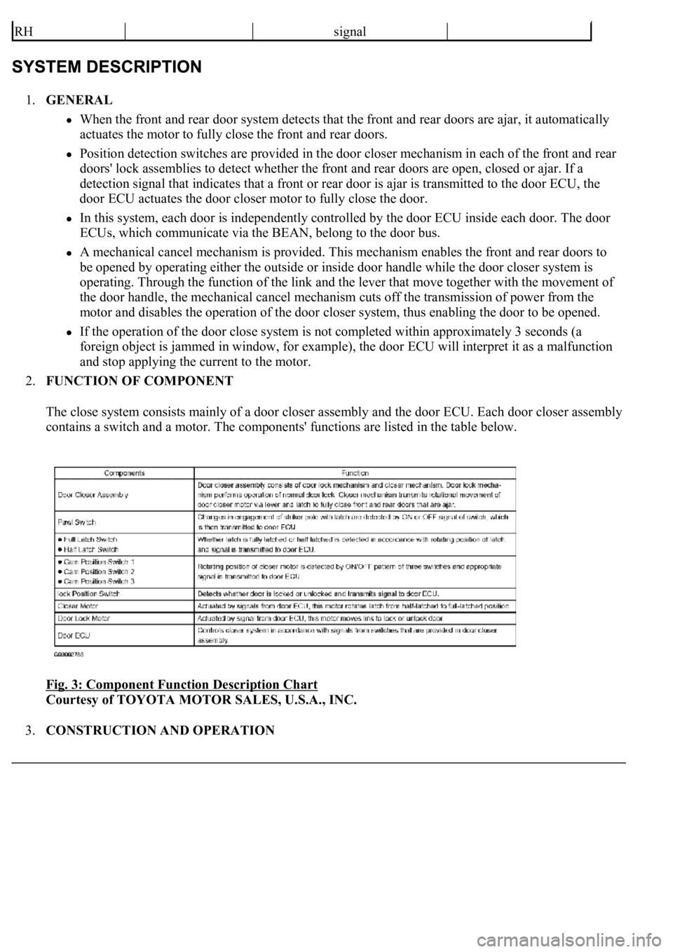
The close system consists mainly of a door closer assembly and the door ECU. Each door closer assembly
contains a switch and a motor. The components' functions are listed in the table below.
Fig. 3: Component Function Description Chart
Courtesy of TOYOTA MOTOR SALES, U.S.A., INC.
3.CONSTRUCTION AND OPERATION
RHsignal
Page 2182 of 4500

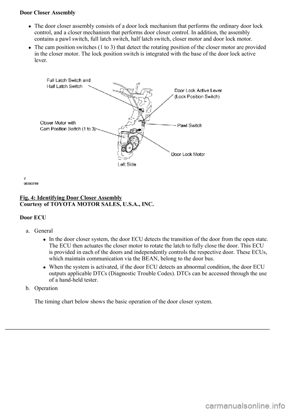
Door Closer Assembly
The door closer assembly consists of a door lock mechanism that performs the ordinary door lock
control, and a closer mechanism that performs door closer control. In addition, the assembly
contains a pawl switch, full latch switch, half latch switch, closer motor and door lock motor.
The cam position switches (1 to 3) that detect the rotating position of the closer motor are provided
<004c005100030057004b004800030046004f0052005600480055000300500052005700520055001100030037004b00480003004f00520046004e0003005300520056004c0057004c0052005100030056005a004c00570046004b0003004c00560003004c00
5100570048004a005500440057004800470003005a004c0057[h the base of the door lock active
lever.
Fig. 4: Identifying Door Closer Assembly
Courtesy of TOYOTA MOTOR SALES, U.S.A., INC.
Door ECU
a. General
In the door closer system, the door ECU detects the transition of the door from the open state.
The ECU then actuates the closer motor to rotate the latch to fully close the door. This ECU
is provided in each of the doors and independently controls the respective door. These ECUs,
which maintain communication via the BEAN, belong to the door bus.
When the system is activated, if the door ECU detects an abnormal condition, the door ECU
outputs applicable DTCs (Diagnostic Trouble Codes). DTCs can be accessed through the use
of a hand-held tester.
b. Operation
The timin
g chart below shows the basic operation of the door closer system.
Page 2184 of 4500
Fig. 6: Cancel Function Diagram
Courtesy of TOYOTA MOTOR SALES, U.S.A., INC.
HINT:
If the child lock of a rear door is engaged, it cannot be canceled by operating the inside door
handle.
d. Closer Motor and Cam Position Switch
Three cam position switches (1 to 3) are provided in the closer motor. In accordance with these
switches' ON/OFF patterns, the closer motor's rotating positions are determined in the 3 segments
of the motor's movin
g range.
Page 2201 of 4500
OK: "ON" (cam position switch 1 to 3 is ON) appears on the screen.
NG: Go to step 2
OK: REPLACE DRIVER DOOR ECU
2.CHECK FRONT DOOR LOCK ASSY LH (CAM POSITION SWITCH)
a. Measure the switch resistance.
Standard:
Fig. 28: Terminals Resistance Reference Chart
Courtesy of TOYOTA MOTOR SALES, U.S.A., INC.
CAM
POS
SW1Cam position switch 1 (OFF/ON)Refer to system description of closer
motor and position switch (SEE
SYSTEM DESCRIPTION
)
-
Page 2202 of 4500
Fig. 29: Checking Front Door Lock Assy LH (Cam Position Switch)
Courtesy of TOYOTA MOTOR SALES, U.S.A., INC.
Refer to the system description for the ON/OFF patterns of the cam position switch (SEE SYSTEM
DESCRIPTION ).
NG: REPLACE FRONT DOOR LOCK ASSY LH
OK: REPLACE DRIVER DOOR ECU
CIRCUIT DESCRIPTION
This DTC is output when a malfunction is detected in the cam position circuit.