Page 1995 of 4500

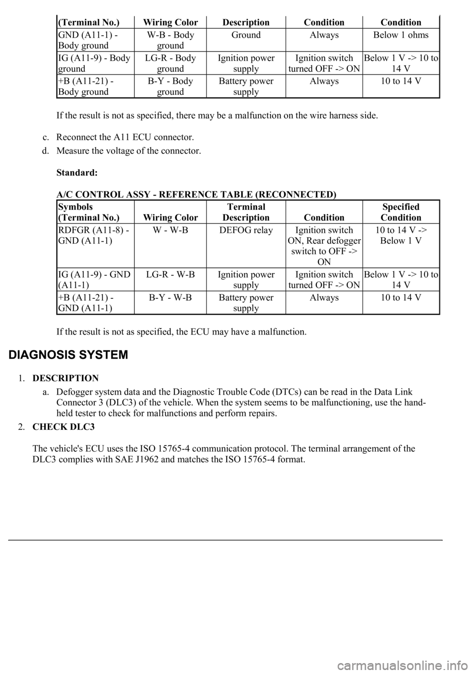
If the result is not as specified, there may be a malfunction on the wire harness side.
c. Reconnect the A11 ECU connector.
d. Measure the voltage of the connector.
Standard:
A/C CONTROL ASSY - REFERENCE TABLE (RECONNECTED)
If the result is not as specified, the ECU may have a malfunction.
1.DESCRIPTION
a. Defogger system data and the Diagnostic Trouble Code (DTCs) can be read in the Data Link
<002600520051005100480046005700520055000300160003000b0027002f00260016000c00030052004900030057004b0048000300590048004b004c0046004f004800110003003a004b0048005100030057004b004800030056005c005600570048005000
03005600480048005000560003005700520003004500480003[malfunctioning, use the hand-
held tester to check for malfunctions and perform repairs.
2.CHECK DLC3
The vehicle's ECU uses the ISO 15765-4 communication protocol. The terminal arrangement of the
DLC3 complies with SAE J1962 and matches the ISO 15765-4 format.
(Terminal No.)Wiring ColorDescriptionConditionCondition
GND (A11-1) -
Body groundW-B - Body
groundGroundAlwaysBelow 1 ohms
IG (A11-9) - Body
groundLG-R - Body
groundIgnition power
supplyIgnition switch
turned OFF -> ONBelow 1 V -> 10 to
14 V
+B (A11-21) -
Body groundB-Y - Body
groundBattery power
supplyAlways10 to 14 V
Symbols
(Terminal No.)
Wiring Color
Terminal
Description
Condition
Specified
Condition
RDFGR (A11-8) -
GND (A11-1)W - W-BDEFOG relayIgnition switch
ON, Rear defogger
switch to OFF ->
ON10 to 14 V ->
Below 1 V
IG (A11-9) - GND
(A11-1)LG-R - W-BIgnition power
supplyIgnition switch
turned OFF -> ONBelow 1 V -> 10 to
14 V
+B (A11-21) -
GND (A11-1)B-Y - W-BBattery power
supplyAlways10 to 14 V
Page 2000 of 4500

that the A/C control is turned on and off.
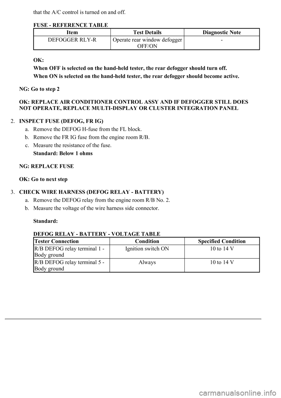
FUSE - REFERENCE TABLE
OK:
When OFF is selected on the hand-held tester, the rear defogger should turn off.
When ON is selected on the hand-held tester, the rear defogger should become active.
NG: Go to step 2
OK: REPLACE AIR CONDITIONER CONTROL ASSY AND IF DEFOGGER STILL DOES
NOT OPERATE, REPLACE MULTI-DISPLAY OR CLUSTER INTEGRATION PANEL
2.INSPECT FUSE (DEFOG, FR IG)
a. Remove the DEFOG H-fuse from the FL block.
b. Remove the FR IG fuse from the engine room R/B.
c. Measure the resistance of the fuse.
Standard: Below 1 ohms
NG: REPLACE FUSE
OK: Go to next step
3.CHECK WIRE HARNESS (DEFOG RELAY - BATTERY)
a. Remove the DEFOG relay from the engine room R/B No. 2.
b. Measure the voltage of the wire harness side connector.
Standard:
DEFOG RELAY - BATTERY - VOLTAGE TABLE
ItemTest DetailsDiagnostic Note
DEFOGGER RLY-ROperate rear window defogger
OFF/ON-
Tester ConnectionConditionSpecified Condition
R/B DEFOG relay terminal 1 -
Body groundIgnition switch ON10 to 14 V
R/B DEFOG relay terminal 5 -
Body groundAlways10 to 14 V
Page 2001 of 4500
Fig. 9: Checking Wire Harness (Defog Relay - Battery)
Courtesy of TOYOTA MOTOR SALES, U.S.A., INC.
NG: REPAIR OR REPLACE HARNESS AND CONNECTOR
OK: Go to next step
4.INSPECT RELAY (Marking: DEFOG)
a. Remove the DEFOG relay from the engine room R/B No. 2.
b. Measure the resistance of the relay.
Standard:
RELAY (Marking: DEFOG) - RESISTANCE TABLE
Tester ConnectionSpecified Condition
3-4Below 1 ohms
3-510 kohms or higher
3-5Below 1 ohms (when battery voltage is applied
to terminals 1 and 2)
Page 2006 of 4500
Fig. 12: Checking Wire Harness (Defog Relay -A/C Control Assy)
Courtesy of TOYOTA MOTOR SALES, U.S.A., INC.
NG: REPAIR OR REPLACE HARNESS AND CONNECTOR
OK: Go to next step
7.INSPECT REAR WINDOW DEFOGGER (WIRE) (See step 3 in INSPECTION
)
NG: REPLACE REAR WINDOW DEFOGGER
OK: REPLACE AIR CONDITIONER CONTROL ASSY
Page 2214 of 4500
b. Measure the voltage and resistance of the wire harness side connector.
Fig. 44: Checking Wire Harness (Driver Door ECU
- Body Ground)
Courtesy of TOYOTA MOTOR SALES, U.S.A., INC.
TERMINALS VOLTAGE AND RESISTANCE REFERENCE
NG: REPAIR OR REPLACE HARNESS AND CONNECTOR
OK: PROCEED TO NEXT CIRCUIT INSPECTION SHOWN ON PROBLEM SYMPTOMS
TABLE
CIRCUIT DESCRIPTION
Tester ConnectionConditionSpecified Condition
D25-1 (GND) - Body groundAlwaysBelow 1 ohms
D25-4 (CPUB) - Body groundAlways10 to 14 V
D25-6 (BDR) - Body groundAlways10 to 14 V
D25-5 (SIG) Body groundIgnition switch ON10 to 14 V
Page 2221 of 4500
OK: Go to Next Step.
3.CHECK WIRE HARNESS (REAR DOOR LH ECU - BATTERY AND BODY GROUND)
a. Disconnect the R13 ECU connector.
b. Measure the voltage and resistance of the wire harness side connector.
Fig. 50: Checking Wire Harness (Rear Door LH ECU
- Body Ground)
Courtesy of TOYOTA MOTOR SALES, U.S.A., INC.
TERMINALS RESISTANCE AND VOLTAGE REFERENCE
NG: REPAIR OR REPLACE HARNESS AND CONNECTOR
OK: PROCEED TO NEXT CIRCUIT INSPECTION SHOWN ON PROBLEM SYMPTOMS
TABLE
Tester ConnectionConditionSpecified Condition
R13-6 (GND) - Body groundAlwaysBelow 1 ohms
R13-1 (CPUB) - Body groundAlways10 to 14 V
R13-2 (BDR) - Body groundAlways10 to 14 V
R13-26 (SIG) Body groundIgnition switch ON10 to 14 V
Page 2477 of 4500
Fig. 46: Identifying Stop Lamp Switch Assy Connector
Courtesy of TOYOTA MOTOR SALES, U.S.A., INC.
NG: REPAIR OR REPLACE HARNESS OR CONNECTOR
OK: Go To Next Step.
4.INSPECT ECM
a. Reconnect the stop lamp switch connector.
b. Disconnect the E2 and E3 connectors from the ECM.
c. Turn the ignition switch to the ON position.
d. Measure the voltage according to the value(s) in the table below.
Standard:
ECM TERMINALS VOLTAGE SPECIFICATION
Pedal conditionTester connectionSpecification
DepressedE2-4 (STP) - Body ground10 to 14 V
ReleasedE2-4 (STP) - Body groundBelow 1 V
Page 2481 of 4500
OK: REPAIR OR REPLACE HARNESS OR CONNECTOR (DRIVER SIDE J/B ECU -
ECM)
6.INSPECT DRIVER SIDE J/B
a. Measure the voltage according to the value(s) in the table below.
Fig. 49: Identifying Driver Side Junction Block ECU Connector Terminals
Courtesy of TOYOTA MOTOR SALES, U.S.A., INC.
Standard:
ECU CONNECTOR TERMINALS VOLTAGE SPECIFICATION
NG: REPAIR OR REPLACE HARNESS OR CONNECTOR (STOP LAMP SWITCH -
DRIVER SIDE J/B ECU)
Pedal conditionTester connectionSpecification
DepressedD3-13 (STPI) - Body ground10 to 14 V
ReleasedD3-13 (STPI) - Body groundBelow 1 V