Page 2582 of 4500
OK: REPAIR OR REPLACE HARNESS OR CONNECTOR (DRIVER SIDE J/B ECU - ECM)
6.INSPECT DRIVER SIDE J/B
a. Measure the voltage according to the value(s) in the table below.
Fig. 51: Identifying Driver Side Junction Block ECU Connector Terminals
Courtesy of TOYOTA MOTOR SALES, U.S.A., INC.
Standard:
ECU CONNECTOR TERMINALS VOLTAGE SPECIFICATION
NG: REPAIR OR REPLACE HARNESS OR CONNECTOR (STOP LAMP SWITCH - DRIVER
SIDE J/B ECU)
OK: REPLACE DRIVER SIDE J/B
Pedal conditionTester connectionSpecification
DepressedD3-13 (STPI) - Body ground10 to 14V
ReleasedD3-13 (STPI) - Body groundBelow 1 V
Page 2602 of 4500
c. Measure the resistance according to the value(s) in the table below.
Standard:
CRUISE CONTROL ECU TERMINALS RESISTANCE SPECIFICATION
NG: REPAIR OR REPLACE WIRE HARNESS OR CONNECTOR
Fig. 75: Disconnecting Cruise Control ECU (Distance Control ECU) Connector
Courtesy of TOYOTA MOTOR SALES, U.S.A., INC.
OK: PROCEED TO NEXT CIRCUIT INSPECTION SHOWN IN PROBLEM SYMPTOMS
TABLE
Tester connectionConditionSpecified value
D2-1 (+B) - Body groundIgnition SW ON10 to 14V
Tester connectionConditionSpecified Value
D2-10 (SGND) - Body groundAlwaysBelow 1 ohms
D2-12 (GND) - Body groundAlwaysBelow 1 ohms
Page 2608 of 4500
Fig. 79: Disconnecting ECM E3 Connector
Courtesy of TOYOTA MOTOR SALES, U.S.A., INC.
NG: REPAIR OR REPLACE WIRE HARNESS OR CONNECTOR
OK: PROCEED TO NEXT CIRCUIT INSPECTION SHOWN IN PROBLEM SYMPTOMS
TABLE
3.CHECK WIRE HARNESS AND CONNECTOR (MILLIMETER WAVE RADAR SENSOR -
DISTANCE CONTROL ECU)
a. Disconnect the cruise control ECU (distance control ECU) connector.
b. Measure the resistance according to the value(s) in the table below.
Standard:
MILLIMETER WAVE RADAR SENSOR AND DISTANCE CONTROL ECU TERMINALS
RESISTANCE
Tester connectionConditionSpecified value
D2-13 (IGB) - M7-5 (IGB)AlwaysBelow 1 ohms
D2-13 (IGB) - Body groundAlways10 kohms or higher
Page 2618 of 4500
Fig. 87: Disconnecting ECM Connector
Courtesy of TOYOTA MOTOR SALES, U.S.A., INC.
NG: REPAIR OR REPLACE HARNESS OR CONNECTOR
OK: Go To Next Step.
5.CHECK HARNESS AND CONNECTOR (SPIRAL CABLE SUB-ASSY - BODY GROUND)
a. Measure the resistance according to the value(s) in the table below.
Standard:
SPIRAL CABLE SUB-ASSY CONNECTOR TERMINALS RESISTANCE
NG: REPAIR OR REPLACE HARNESS OR CONNECTOR
Fig. 88: Identifying Spiral Cable Sub
-Assy Connector Terminals
Tester connectionConditionSpecified value
C13-3 - Body groundAlwaysBelow 1 ohms
Page 2625 of 4500
Fig. 91: Disconnecting E2 Connector From ECM
Courtesy of TOYOTA MOTOR SALES, U.S.A., INC.
NG: REPAIR OR REPLACE HARNESS OR CONNECTOR (DLC3 - ECM)
OK: Go To Next Step.
2.CHECK HARNESS AND CONNECTOR (CG of DLC3 - BODY GROUND)
a. Measure the resistance according to the value(s) in the table below.
Standard:
ECM CONNECTOR TERMINALS RESISTANCE
NG: REPAIR OR REPLACE HARNESS OR CONNECTOR (DLC3 - BODY GROUND)
Fig. 92: Identifying DLC3 Connector (CG) Terminals
Courtesy of TOYOTA MOTOR SALES, U.S.A., INC.
Tester connectionConditionSpecified condition
CG (D1-4) - Body groundAlwaysBelow 1 ohms
Page 2626 of 4500
OK: Go To Next Step.
3.CHECK HARNESS AND CONNECTOR (TC of DLC3 - BODY GROUND)
a. Measure the resistance according to the value(s) in the table below.
Standard:
ECM CONNECTOR TERMINALS RESISTANCE
NG: REPAIR OR REPLACE WIRE HARNESS AND EACH ECU
Fig. 93: Identifying DLC3 Connector (TC) Terminals
Courtesy of TOYOTA MOTOR SALES, U.S.A., INC.
OK: REPLACE ECM (SEE REPLACEMENT
)
Tester connectionConditionSpecified condition
TC (D1-13) - Body groundAlways10 kohms or higher
Page 2669 of 4500

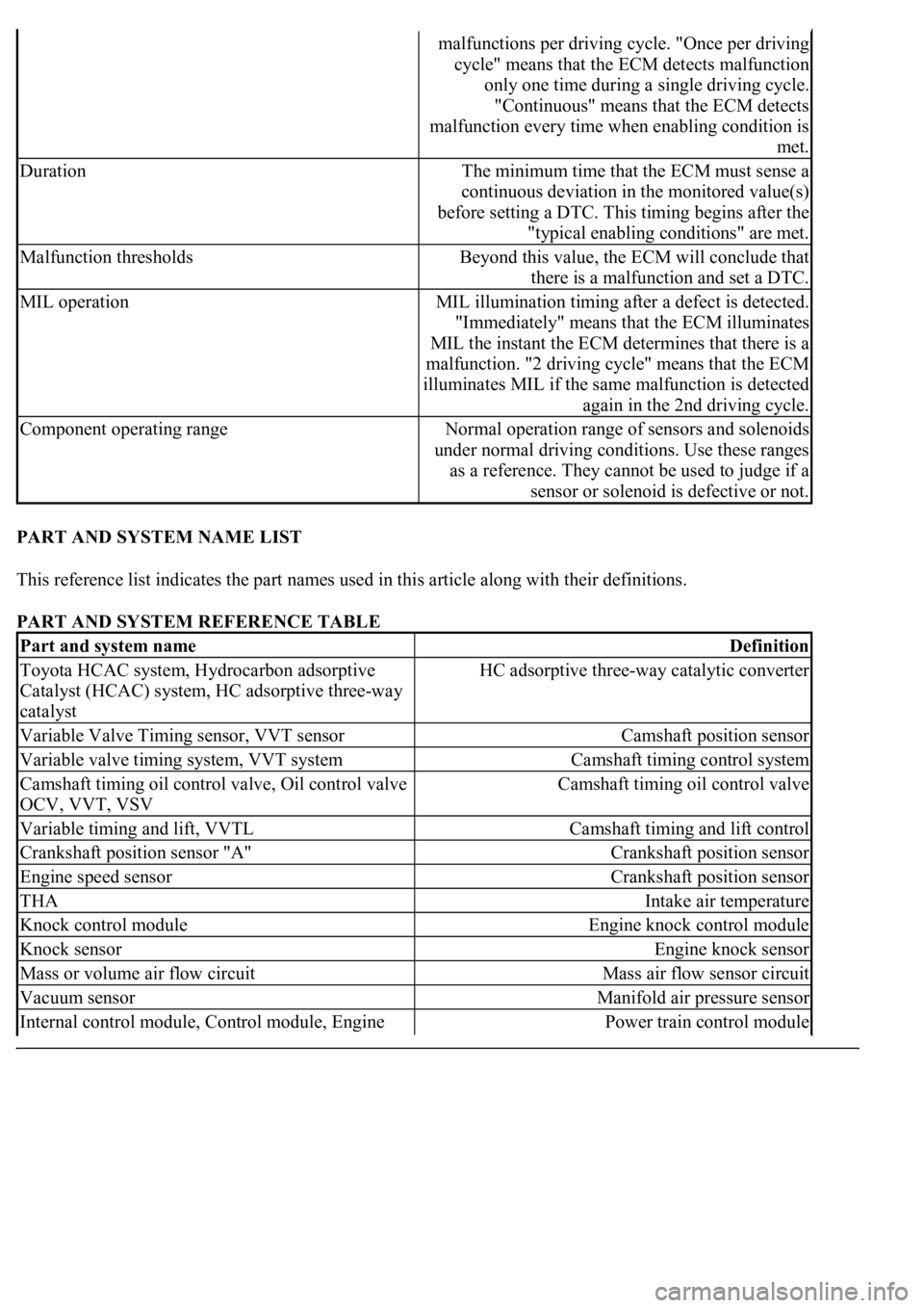
PART AND SYSTEM NAME LIST
This reference list indicates the part names used in this article along with their definitions.
PART AND SYSTEM REFERENCE TABLE
malfunctions per driving cycle. "Once per driving
cycle" means that the ECM detects malfunction
only one time during a single driving cycle.
"Continuous" means that the ECM detects
malfunction every time when enabling condition is
met.
DurationThe minimum time that the ECM must sense a
continuous deviation in the monitored value(s)
before setting a DTC. This timing begins after the
"typical enabling conditions" are met.
Malfunction thresholdsBeyond this value, the ECM will conclude that
there is a malfunction and set a DTC.
MIL operationMIL illumination timing after a defect is detected.
"Immediately" means that the ECM illuminates
MIL the instant the ECM determines that there is a
malfunction. "2 driving cycle" means that the ECM
illuminates MIL if the same malfunction is detected
again in the 2nd driving cycle.
Component operating rangeNormal operation range of sensors and solenoids
under normal driving conditions. Use these ranges
as a reference. They cannot be used to judge if a
sensor or solenoid is defective or not.
Part and system nameDefinition
Toyota HCAC system, Hydrocarbon adsorptive
Catalyst (HCAC) system, HC adsorptive three-way
catalystHC adsorptive three-way catalytic converter
Variable Valve Timing sensor, VVT sensorCamshaft position sensor
Variable valve timing system, VVT systemCamshaft timing control system
Camshaft timing oil control valve, Oil control valve
OCV, VVT, VSVCamshaft timing oil control valve
Variable timing and lift, VVTLCamshaft timing and lift control
Crankshaft position sensor "A"Crankshaft position sensor
Engine speed sensorCrankshaft position sensor
THAIntake air temperature
Knock control moduleEngine knock control module
Knock sensorEngine knock sensor
Mass or volume air flow circuitMass air flow sensor circuit
Vacuum sensorManifold air pressure sensor
Internal control module, Control module, Engine Power train control module
Page 2712 of 4500
Fig. 34: Identifying DLC3 Terminals
Courtesy of TOYOTA MOTOR SALES, U.S.A., INC.
FREEZE FRAME DATA
Freeze frame data records the engine conditions (fuel system, calculated load, engine coolant temperature, fuel
trim, engine speed, vehicle speed, etc.) when a malfunction is detected. When troubleshooting, freeze frame
data can help determine if the vehicle was running or stopped, if the engine was warmed up or not, if the air/fuel
ratio was Lean or Rich, and other data from the time the malfunction occurred.
The hand-held tester records freeze frame data in five different instances: 1) 3 times before the DTC is set, 2)
once when the DTC is set, and 3) once after the DTC is set. These data can be used to simulate the vehicle's
condition around the time when the malfunction occurred. The data may help find the cause of the malfunction,
or
judge if the DTC is being caused by a temporary malfunction or not.