Page 2495 of 4500
Fig. 64: Disconnecting Laser Sensor Connector
Courtesy of TOYOTA MOTOR SALES, U.S.A., INC.
NG: REPAIR OR REPLACE WIRE HARNESS OR CONNECTOR
OK: Go To Next Step.
2.INSPECT CRUISE CONTROL ECU ASSY (DISTANCE CONTROL ECU)
a. Reconnect the cruise control ECU (distance control ECU) connector.
b. Turn the ignition switch to the ON position.
c. Measure the voltage according to the value(s) in the table below.
Standard:
CRUISE CONTROL ECU TERMINALS VOLTAGE SPECIFICATION
Tester connectionConditionSpecified value
D2-13 (IGB) - Body groundIgnition SW ON10 to 14 V
Page 2502 of 4500
c. Measure the resistance according to the value(s) in the table below.
Standard:
CRUISE CONTROL ECU TERMINALS RESISTANCE SPECIFICATION
NG: REPAIR OR REPLACE WIRE HARNESS OR CONNECTOR
Fig. 70: Disconnecting Cruise Control ECU (Distance Control ECU) Connector
Courtesy of TOYOTA MOTOR SALES, U.S.A., INC.
OK: PROCEED TO NEXT CIRCUIT INSPECTION SHOWN IN PROBLEM SYMPTOMS
TABLE
Tester connectionConditionSpecified value
D2-1 (+B) - Body groundIgnition SW ON10 to 14 V
Tester connectionConditionSpecified value
D2-10 (SGND) - Body groundAlwaysBelow 1 ohms
D2-12 (GND) - Body groundAlwaysBelow 1 ohms
Page 2508 of 4500
Fig. 74: Disconnecting ECM E3 Connector
Courtesy of TOYOTA MOTOR SALES, U.S.A., INC.
NG: REPAIR OR REPLACE WIRE HARNESS OR CONNECTOR
OK: PROCEED TO NEXT CIRCUIT INSPECTION SHOWN IN PROBLEM SYMPTOMS
TABLE
3.CHECK WIRE HARNESS AND CONNECTOR (LASER SENSOR - DISTANCE CONTROL
ECU)
a. Disconnect the cruise control ECU (distance control ECU) connector.
b. Measure the resistance according to the value(s) in the table below.
Standard:
LASER SENSOR AND DISTANCE CONTROL ECU TERMINALS RESISTANCE
SPECIFICATION
Tester connectionConditionSpecified value
D2-13 (IGB) - L1-5 (IGB)AlwaysBelow 1 ohms
D2-13 (IGB) - Body groundAlways10 kohms or higher
Page 2517 of 4500
Fig. 82: Disconnecting ECM Connector Terminals
Courtesy of TOYOTA MOTOR SALES, U.S.A., INC.
NG: REPAIR OR REPLACE HARNESS OR CONNECTOR
OK: Go To Next Step.
5.CHECK HARNESS AND CONNECTOR (SPIRAL CABLE SUB-ASSY - BODY GROUND)
a. Measure the resistance according to the value(s) in the table below.
Standard:
SPIRAL CABLE SUB-ASSY CONNECTOR TERMINALS RESISTANCE
SPECIFICATION
Fig. 83: Identifying Spiral Cable Sub
-Assy Connectors
Courtesy of TOYOTA MOTOR SALES, U.S.A., INC.
Tester connectionConditionSpecified value
C13-3 - Body groundAlwaysBelow 1 ohms
Page 2518 of 4500

NG: REPAIR OR REPLACE HARNESS OR CONNECTOR
OK: REPLACE ECM (SEE REPLACEMENT )
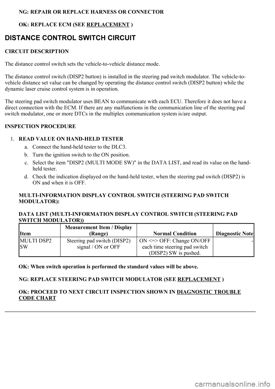
CIRCUIT DESCRIPTION
The distance control switch sets the vehicle-to-vehicle distance mode.
The distance control switch (DISP2 button) is installed in the steering pad switch modulator. The vehicle-to-
vehicle distance set value can be changed by operating the distance control switch (DISP2 button) while the
dynamic laser cruise control system is in operation.
The steering pad switch modulator uses BEAN to communicate with each ECU. Therefore it does not have a
direct connection with the ECM. If there are any malfunctions in the communication line of the steering pad
switch modulator, one or more DTCs in the multiplex communication system is/are output.
INSPECTION PROCEDURE
1.READ VALUE ON HAND-HELD TESTER
a. Connect the hand-held tester to the DLC3.
b. Turn the ignition switch to the ON position.
c. Select the item "DISP2 (MULTI MODE SW)" in the DATA LIST, and read its value on the hand-
held tester.
d. Check the indication displayed on the hand-held tester, when the steering pad switch (DISP2) is
ON and when it is OFF.
MULTI-INFORMATION DISPLAY CONTROL SWITCH (STEERING PAD SWITCH
MODULATOR):
DATA LIST (MULTI-INFORMATION DISPLAY CONTROL SWITCH (STEERING PAD
SWITCH MODULATOR))
OK: When switch operation is performed the standard values will be above.
NG: REPLACE STEERING PAD SWITCH MODULATOR (SEE REPLACEMENT
)
OK: PROCEED TO NEXT CIRCUIT INSPECTION SHOWN IN DIAGNOSTIC TROUBLE
CODE CHART
Item
Measurement Item / Display
(Range)
Normal ConditionDiagnostic Note
MULTI DSP2
SWSteering pad switch (DISP2)
signal / ON or OFFON <=> OFF: Change ON/OFF
each time steering pad switch
(DISP2) SW is pushed.-
Page 2524 of 4500
Fig. 86: Disconnecting E2 Connector From ECM
Courtesy of TOYOTA MOTOR SALES, U.S.A., INC.
NG: REPAIR OR REPLACE HARNESS OR CONNECTOR (DLC3 - ECM)
OK: Go To Next Step.
2.CHECK HARNESS AND CONNECTOR (CG of DLC3 - BODY GROUND)
a. Measure the resistance according to the value(s) in the table below.
Standard:
ECM CONNECTOR TERMINALS RESISTANCE SPECIFICATION
Fig. 87: Identifying DLC3 Connector (CG) Terminals
Courtesy of TOYOTA MOTOR SALES, U.S.A., INC.
NG: REPAIR OR REPLACE HARNESS OR CONNECTOR (DLC3 - BODY GROUND)
Tester connectionConditionSpecified condition
CG (D1-4) - Body groundAlwaysBelow 1 ohms
Page 2525 of 4500
OK: Go To Next Step.
3.CHECK HARNESS AND CONNECTOR (TC of DLC3 - BODY GROUND)
a. Measure the resistance according to the value(s) in the table below.
Standard:
ECM CONNECTOR TERMINALS RESISTANCE SPECIFICATION
Fig. 88: Identifying DLC3 Connector (TC) Terminals
Courtesy of TOYOTA MOTOR SALES, U.S.A., INC.
NG: REPAIR OR REPLACE WIRE HARNESS AND EACH ECU
OK: REPLACE ECM (SEE REPLACEMENT
)
Tester connectionConditionSpecified condition
TC (D1-13) - Body groundAlways10 kohms or higher
Page 2578 of 4500
Fig. 48: Identifying Stop Lamp Switch Assy Connector
Courtesy of TOYOTA MOTOR SALES, U.S.A., INC.
NG: REPAIR OR REPLACE HARNESS OR CONNECTOR
OK: Go To Next Step.
4.INSPECT ECM
a. Reconnect the stop lamp switch connector.
b. Disconnect the E2 and E3 connectors from the ECM.
c. Turn the ignition switch to the ON position.
d. Measure the voltage according to the value(s) in the table below.
Standard:
ECM CONNECTOR TERMINALS VOLTAGE SPECIFICATION
Pedal conditionTester connectionSpecification
DepressedE2-4 (STP) - Body ground10 to 14V
ReleasedE2-4 (STP) - Body groundBelow 1 V