Page 2869 of 4500
OK: REPAIR OR REPLACE TRANSMISSION WIRE (See step 5 on REPLACEMENT)
DTC P2757: TORQUE CONVERTER CLUTCH PRESSURE CONTROL SOLENOID
PERFORMANCE (SHIFT SOLENOID VALVE SLU)
SYSTEM DESCRIPTION
The ECM uses the signals from the throttle position sensor, Air-flow meter, turbine (input) speed sensor, output
speed sensor and crankshaft position sensor to monitor the engagement condition of the lock-up clutch.
Then the ECM compares the engagement condition of the lock-up clutch with the lock-up schedule in the ECM
memory to detect a mechanical problems of the shift solenoid valve SLU, valve body and torque converter
clutch.
Fig. 173: Identifying Manual Transmission
Courtesy of TOYOTA MOTOR SALES, U.S.A., INC.
Page 2877 of 4500

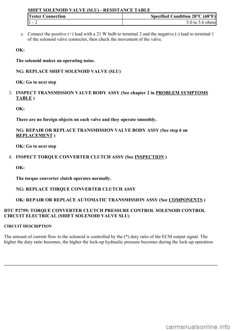
SHIFT SOLENOID VALVE (SLU) - RESISTANCE TABLE
c. Connect the positive (+) lead with a 21 W bulb to terminal 2 and the negative (-) lead to terminal 1
of the solenoid valve connector, then check the movement of the valve.
OK:
The solenoid makes an operating noise.
NG: REPLACE SHIFT SOLENOID VALVE (SLU)
OK: Go to next step
3.INSPECT TRANSMISSION VALVE BODY ASSY (See chapter 2 in PROBLEM SYMPTOMS
TABLE )
OK:
There are no foreign objects on each valve and they operate smoothly.
NG: REPAIR OR REPLACE TRANSMISSION VALVE BODY ASSY (See step 6 on
REPLACEMENT
)
OK: Go to next step
4.INSPECT TORQUE CONVERTER CLUTCH ASSY (See INSPECTION
)
OK:
The torque converter clutch operates normally.
NG: REPLACE TORQUE CONVERTER CLUTCH ASSY
OK: REPAIR OR REPLACE AUTOMATIC TRANSMISSION ASSY (See COMPONENTS
)
DTC P2759: TORQUE CONVERTER CLUTCH PRESSURE CONTROL SOLENOID CONTROL
CIRCUIT ELECTRICAL (SHIFT SOLENOID VALVE SLU)
CIRCUIT DESCRIPTION
The amount of current flow to the solenoid is controlled by the (*) duty ratio of the ECM output signal. The
hi
gher the duty ratio becomes, the higher the lock-up hydraulic pressure becomes during the lock-up operation.
Tester ConnectionSpecified Condition 20°C (68°F)
1 - 25.0 to 5.6 ohms
Page 2883 of 4500

Courtesy of TOYOTA MOTOR SALES, U.S.A., INC.
Standard:
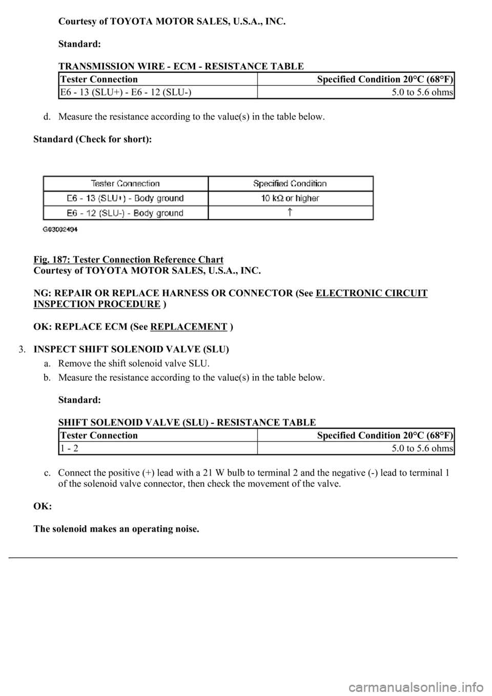
TRANSMISSION WIRE - ECM - RESISTANCE TABLE
d. Measure the resistance according to the value(s) in the table below.
Standard (Check for short):
Fig. 187: Tester Connection Reference Chart
Courtesy of TOYOTA MOTOR SALES, U.S.A., INC.
NG: REPAIR OR REPLACE HARNESS OR CONNECTOR (See ELECTRONIC CIRCUIT
INSPECTION PROCEDURE )
OK: REPLACE ECM (See REPLACEMENT
)
3.INSPECT SHIFT SOLENOID VALVE (SLU)
a. Remove the shift solenoid valve SLU.
b. Measure the resistance according to the value(s) in the table below.
Standard:
SHIFT SOLENOID VALVE (SLU) - RESISTANCE TABLE
c. Connect the positive (+) lead with a 21 W bulb to terminal 2 and the negative (-) lead to terminal 1
of the solenoid valve connector, then check the movement of the valve.
OK:
The solenoid makes an operating noise.
Tester ConnectionSpecified Condition 20°C (68°F)
E6 - 13 (SLU+) - E6 - 12 (SLU-)5.0 to 5.6 ohms
Tester ConnectionSpecified Condition 20°C (68°F)
1 - 25.0 to 5.6 ohms
Page 2889 of 4500
Fig. 192: Identifying Transmission Control Switch Connector Terminals
Courtesy of TOYOTA MOTOR SALES, U.S.A., INC.
Standard:
TRANSMISSION CONTROL SWITCH - BODY GROUND - RESISTANCE TABLE
NG: REPAIR OR REPLACE HARNESS OR CONNECTOR (See ELECTRONIC CIRCUIT
INSPECTION PROCEDURE )
Tester ConnectionSpecified Condition
5 - Body groundBelow 1 ohms
Page 2896 of 4500
Fig. 200: Identifying Pattern Select Switch Connector Terminals
Courtesy of TOYOTA MOTOR SALES, U.S.A., INC.
Standard:
PATTERN SELECT SWITCH NO. 1 - BODY GROUND - RESISTANCE TABLE
NG: REPAIR OR REPLACE HARNESS OR CONNECTOR (See ELECTRONIC CIRCUIT
INSPECTION PROCEDURE )
OK: Go to next step
Tester ConnectionSpecified Condition
1 - Body groundBelow 1 ohms
Page 2901 of 4500
a. Disconnect the connector of pattern select switch.
b. Measure the resistance according to the value(s) in the table below.
Fig. 206: Identifying Pattern Select Switch Connector Terminals
Courtesy of TOYOTA MOTOR SALES, U.S.A., INC.
Standard:
PATTERN SELECT SWITCH NO. 1 - BODY GROUND - RESISTANCE TABLE
NG: REPAIR OR REPLACE HARNESS OR CONNECTOR (See ELECTRONIC CIRCUIT
INSPECTION PROCEDURE )
Tester ConnectionSpecified Condition
1 - Body groundBelow 1 ohms
Page 2947 of 4500
Courtesy of TOYOTA MOTOR SALES, U.S.A., INC.
a. Check the output voltage.
1. Apply battery voltage across terminals 1 (+B) and 2 (E2G).
2. Using a voltmeter, connect the positive (+) tester probe to terminal VG, and negative (-)
tester probe to terminal E2G.
3. Blow air into the MAF meter, and check that the voltage fluctuates.
b. Measure the resistance between terminals 4 (THA) and 5 (E2).
STANDARD:
If the result is not as specified, replace the MAF meter.
2.INSPECT CAMSHAFT TIMING OIL CONTROL VALVE ASSY
ConditionSpecified Condition
-20°C (-4°F)13.6 to 18.4 kohms
20°C (68°F)2.21 to 2.69 kohms
60°C (140°F)0.493 to 0.667 kohms
Page 3168 of 4500

A: Go to next step
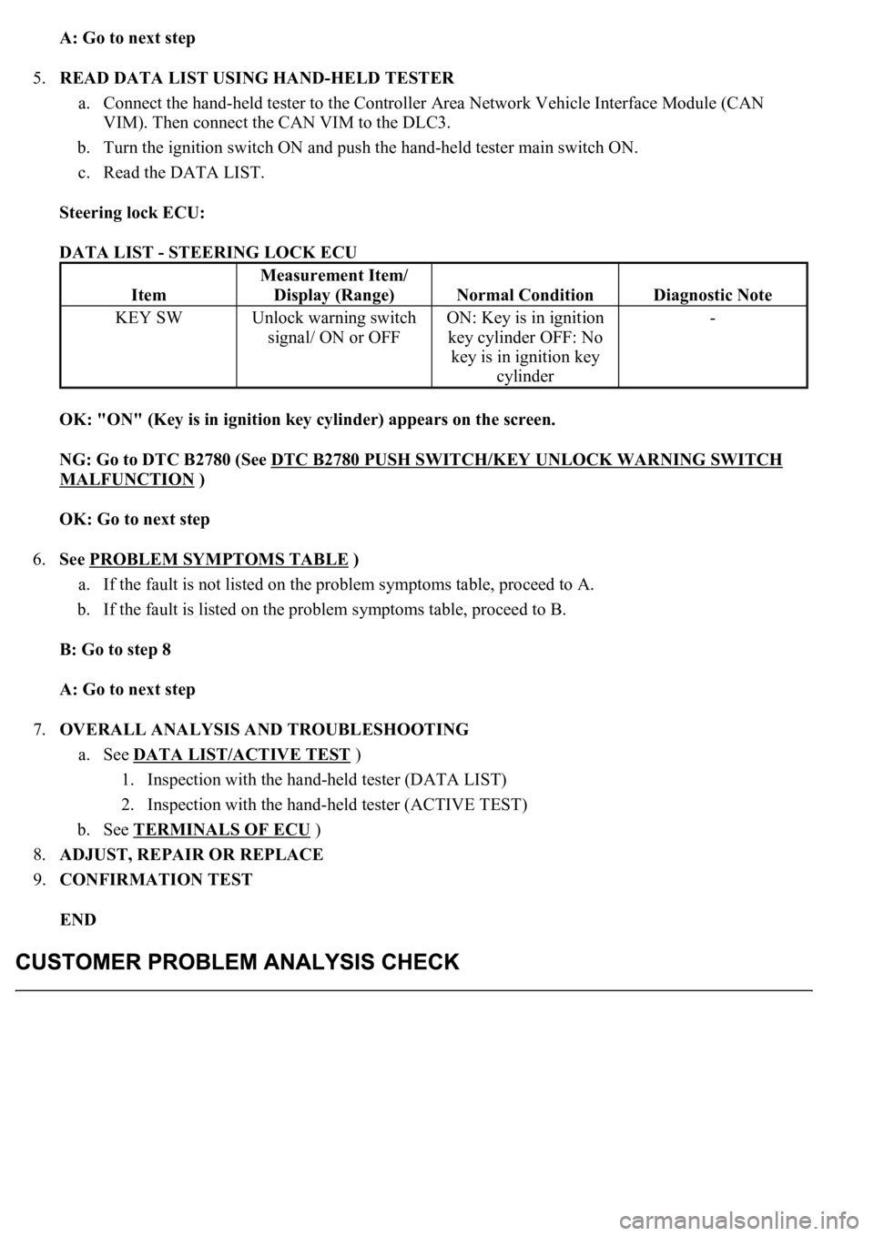
5.READ DATA LIST USING HAND-HELD TESTER
a. Connect the hand-held tester to the Controller Area Network Vehicle Interface Module (CAN
VIM). Then connect the CAN VIM to the DLC3.
b. Turn the ignition switch ON and push the hand-held tester main switch ON.
c. Read the DATA LIST.
Steering lock ECU:
DATA LIST - STEERING LOCK ECU
OK: "ON" (Key is in ignition key cylinder) appears on the screen.
NG: Go to DTC B2780 (See DTC B2780 PUSH SWITCH/KEY UNLOCK WARNING SWITCH
MALFUNCTION )
OK: Go to next step
6.See PROBLEM SYMPTOMS TABLE
)
a. If the fault is not listed on the problem symptoms table, proceed to A.
b. If the fault is listed on the problem symptoms table, proceed to B.
B: Go to step 8
A: Go to next step
7.OVERALL ANALYSIS AND TROUBLESHOOTING
a. See DATA LIST/ACTIVE TEST
)
1. Inspection with the hand-held tester (DATA LIST)
2. Inspection with the hand-held tester (ACTIVE TEST)
b. See TERMINALS OF ECU
)
8.ADJUST, REPAIR OR REPLACE
9.CONFIRMATION TEST
END
Item
Measurement Item/
Display (Range)
Normal ConditionDiagnostic Note
KEY SWUnlock warning switch
signal/ ON or OFFON: Key is in ignition
key cylinder OFF: No
key is in ignition key
cylinder-