Page 3273 of 4500

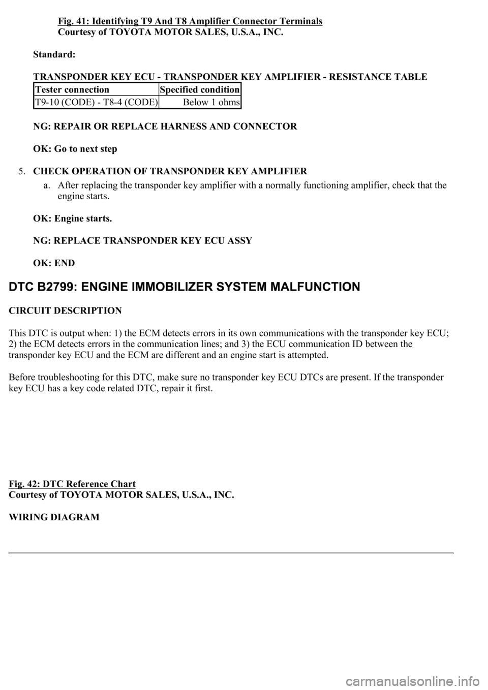
Fig. 41: Identifying T9 And T8 Amplifier Connector Terminals
Courtesy of TOYOTA MOTOR SALES, U.S.A., INC.
Standard:
TRANSPONDER KEY ECU - TRANSPONDER KEY AMPLIFIER - RESISTANCE TABLE
NG: REPAIR OR REPLACE HARNESS AND CONNECTOR
OK: Go to next step
5.CHECK OPERATION OF TRANSPONDER KEY AMPLIFIER
a. After replacing the transponder key amplifier with a normally functioning amplifier, check that the
engine starts.
OK: Engine starts.
NG: REPLACE TRANSPONDER KEY ECU ASSY
OK: END
CIRCUIT DESCRIPTION
This DTC is output when: 1) the ECM detects errors in its own communications with the transponder key ECU;
2) the ECM detects errors in the communication lines; and 3) the ECU communication ID between the
transponder key ECU and the ECM are different and an engine start is attempted.
Before troubleshooting for this DTC, make sure no transponder key ECU DTCs are present. If the transponder
key ECU has a key code related DTC, repair it first.
Fig. 42: DTC Reference Chart
Courtesy of TOYOTA MOTOR SALES, U.S.A., INC.
WIRING DIAGRAM
Tester connectionSpecified condition
T9-10 (CODE) - T8-4 (CODE)Below 1 ohms
Page 3276 of 4500
Fig. 44: Identifying T9 ECU And E2 ECM Connector Terminals
Courtesy of TOYOTA MOTOR SALES, U.S.A., INC.
Standard:
TRANSPONDER KEY ECU ASSY - ECM - RESISTANCE TABLE
NG: REPAIR OR REPLACE HARNESS AND CONNECTOR
OK: REPLACE ECM
CIRCUIT DESCRIPTION
This circuit provides power to operate the transponder key ECU.
WIRING DIAGRAM
Tester connectionSpecified condition
T9-6 (EFIO) - E2-6 (IMI)Below 1 ohms
T9-7 (EFII) - E2-7 (IMO)Below 1 ohms
T9-6 (EFIO) or E2-6 (IMI) -Body ground10 kohms or higher
T9-7 (EFII) or E2-7 (IMO) -Body ground10 kohms or higher
Page 3278 of 4500
2.CHECK WIRE HARNESS (TRANSPONDER KEY ECU ASSY - BATTERY AND BODY
GROUND)
a. Disconnect the T9 ECU connector.
b. Measure the resistance and voltage of the wire harness side connector.
Fig. 46: Identifying T9 ECU Connector Terminals
Courtesy of TOYOTA MOTOR SALES, U.S.A., INC.
Standard:
TRANSPONDER KEY ECU - BATTERY AND BODY GROUND - RESISTANCE TABLE
NG: REPAIR OR REPLACE HARNESS AND CONNECTOR
OK: REPLACE TRANSPONDER KEY ECU ASSY
Tester ConnectionSpecified ConditionCondition
T9-1 (CPUB) -Body groundAlways10 to 14V
T9-2 (IG2) - Body groundIgnition switch OFF --> ON0V --> 10 to 14 V
T9-14 (GND) -Body groundAlwaysBelow 1 ohms
Page 3934 of 4500
Courtesy of TOYOTA MOTOR SALES, U.S.A., INC.
Standard:
TESTER CONNECTION AND SPECIFIED CONDITION
NG: REPAIR OR REPLACE HARNESS AND CONNECTOR
OK: PROCEED TO NEXT CIRCUIT INSPECTION SHOWN ON PROBLEM SYMPTOMS
TABLE
CIRCUIT DESCRIPTION
This circuit supplies power to operate the driver side J/B ECU.
WIRING DIAGRAM
Tester ConnectionSwitch ConditionSpecified Condition
D27-14 (+B) - Body groundAlways10 to 14 V
D28-9 (SYSB) - Body groundAlways10 to 14 V
D28-10 (IG) - Body groundIgnition switch OFF --> ON0 V --> 10 to 14 V
D27-6 (GND) - Body groundAlwaysBelow 1 ohms
D28-1 (SGND) - Body groundAlwaysBelow 1 ohms
Page 3937 of 4500
a. Disconnect the D25 ECU connector.
b. Measure the voltage and resistance of the wire harness side connector.
Standard:
TESTER CONNECTION AND SPECIFIED CONDITION
Fig. 20: Identifying D25 Driver Door ECU Connector Terminals
Courtesy of TOYOTA MOTOR SALES, U.S.A., INC.
NG: REPAIR OR REPLACE HARNESS AND CONNECTOR
OK: PROCEED TO NEXT CIRCUIT INSPECTION SHOWN ON PROBLEM SYMPTOMS
TABLE
Tester connectionConditionSpecified condition
D25-4 (CPUB) - Body groundAlways10 to 14 V
D25-6 (BDR) - Body groundAlways10 to 14 V
D25-5 (SIG) - Body groundIgnition switch OFF --> ON0 V --> 10 to 14 V
D25-1 (GND) - Body groundAlwaysBelow 1 ohms
Page 4162 of 4500
Fig. 2: Identifying Engine Room No. 1 Junction & Relay Block Components
Courtesy of TOYOTA MOTOR SALES, U.S.A., INC.
Engine Room No. 1 Junction & Relay Block Fuses
FuseSystem
7.5AA/C IGAutomatic Air Conditioning (Front)
7.5AEFI NO.2Engine Control
7.5AFR IGABS
Automatic Air Conditioning (Front)
Back-Up Light
Charging
Clock (w/ LEXUS Navigation System)
Cruise Control
Door Closer (w/ Smart Key System)
Door Closer (w/o Smart Key System)
Door Lock Control (w/ Smart Key System)
Door Lock Control (w/o Smart Key System)
Page 4166 of 4500

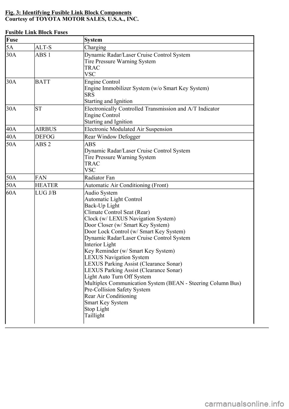
Fig. 3: Identifying Fusible Link Block Components
Courtesy of TOYOTA MOTOR SALES, U.S.A., INC.
Fusible Link Block Fuses
FuseSystem
5AALT-SCharging
30AABS 1Dynamic Radar/Laser Cruise Control System
Tire Pressure Warning System
TRAC
VSC
30ABATTEngine Control
Engine Immobilizer System (w/o Smart Key System)
SRS
Starting and Ignition
30ASTElectronically Controlled Transmission and A/T Indicator
Engine Control
Starting and Ignition
40AAIRBUSElectronic Modulated Air Suspension
40ADEFOGRear Window Defogger
50AABS 2ABS
Dynamic Radar/Laser Cruise Control System
Tire Pressure Warning System
TRAC
VSC
50AFANRadiator Fan
50AHEATERAutomatic Air Conditioning (Front)
60ALUG J/BAudio System
Automatic Light Control
Back-Up Light
Climate Control Seat (Rear)
Clock (w/ LEXUS Navigation System)
Door Closer (w/ Smart Key System)
Door Lock Control (w/ Smart Key System)
Dynamic Radar/Laser Cruise Control System
Interior Light
Key Reminder (w/ Smart Key System)
LEXUS Navigation System
LEXUS Parking Assist (Clearance Sonar)
LEXUS Parking Assist (Clearance Sonar)
Light Auto Turn Off System
Multiplex Communication System (BEAN - Steering Column Bus)
Pre-Collision Safety System
Rear Air Conditioning
Smart Key System
Stop Light
Taillight
Page 4170 of 4500

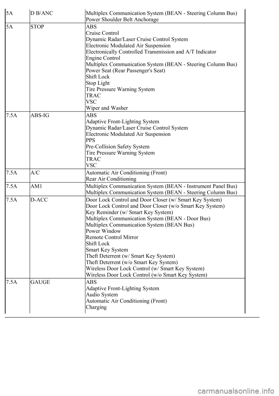
5AD B/ANCMultiplex Communication System (BEAN - Steering Column Bus)
Power Shoulder Belt Anchorage
5ASTOPABS
Cruise Control
Dynamic Radar/Laser Cruise Control System
Electronic Modulated Air Suspension
Electronically Controlled Transmission and A/T Indicator
Engine Control
Multiplex Communication System (BEAN - Steering Column Bus)
Power Seat (Rear Passenger's Seat)
Shift Lock
Stop Light
Tire Pressure Warning System
TRAC
VSC
Wiper and Washer
7.5AABS-IGABS
Adaptive Front-Lighting System
Dynamic Radar/Laser Cruise Control System
Electronic Modulated Air Suspension
PPS
Pre-Collision Safety System
Tire Pressure Warning System
TRAC
VSC
7.5AA/CAutomatic Air Conditioning (Front)
Rear Air Conditioning
7.5AAM1Multiplex Communication System (BEAN - Instrument Panel Bus)
Multiplex Communication System (BEAN - Steering Column Bus)
7.5AD-ACCDoor Lock Control and Door Closer (w/ Smart Key System)
Door Lock Control and Door Closer (w/o Smart Key System)
Key Reminder (w/ Smart Key System)
Multiplex Communication System (BEAN - Door Bus)
Multiplex Communication System (BEAN Bus)
Power Window
Remote Control Mirror
Shift Lock
Smart Key System
Theft Deterrent (w/ Smart Key System)
Theft Deterrent (w/o Smart Key System)
Wireless Door Lock Control (w/ Smart Key System)
Wireless Door Lock Control (w/o Smart Key System)
7.5AGAUGEABS
Adaptive Front-Lighting System
Audio System
Automatic Air Conditioning (Front)
Charging