Page 2730 of 4500
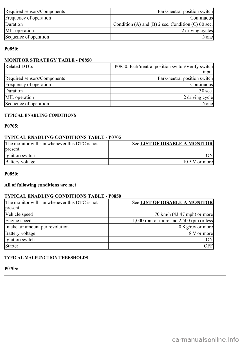
P0850:
MONITOR STRATEGY TABLE - P0850
TYPICAL ENABLING CONDITIONS
P0705:
TYPICAL ENABLING CONDITIONS TABLE - P0705
P0850:
All of following conditions are met
TYPICAL ENABLING CONDITIONS TABLE - P0850
TYPICAL MALFUNCTION THRESHOLDS
P0705:
Required sensors/ComponentsPark/neutral position switch
Frequency of operationContinuous
DurationCondition (A) and (B) 2 sec. Condition (C) 60 sec.
MIL operation2 driving cycles
Sequence of operationNone
Related DTCsP0850: Park/neutral position switch/Verify switch
input
Required sensors/ComponentsPark/neutral position switch
Frequency of operationContinuous
Duration30 sec.
MIL operation2 driving cycle
Sequence of operationNone
The monitor will run whenever this DTC is not
present.See LIST OF DISABLE A MONITOR
Ignition switchON
Battery voltage10.5 V or more
The monitor will run whenever this DTC is not
present.See LIST OF DISABLE A MONITOR
Vehicle speed70 km/h (43.47 mph) or more
Engine speed1,000 rpm or more and 2,500 rpm or less
Intake air amount per revolution0.8 g/rev or more
Battery voltage8 V or more
Ignition switchON
StarterOFF
Page 2747 of 4500
Fig. 63: Transmission Wire Connector Reference Chart
Courtesy of TOYOTA MOTOR SALES, U.S.A., INC.
NG: REPAIR OR REPLACE TRANSMISSION WIRE (See step 5 on REPLACEMENT
)
OK: Go to next step
2.CHECK HARNESS AND CONNECTOR (TRANSMISSION WIRE - ECM)
a. Connect the transmission wire connector to the transmission.
b. Disconnect the ECM connector.
c. Measure the resistance according to the value(s) in the table below.
Standard:
TRANSMISSION WIRE - ECM - RESISTANCE TABLE
d. Measure the resistance according to the value(s) in the table below.
Fig. 64: Disconnecting ECM Connector
Tester ConnectionSpecified Condition
E6 - 27 (OIL) - E6 - 26 (EOIL)79ohms to 156kohms
Page 2749 of 4500
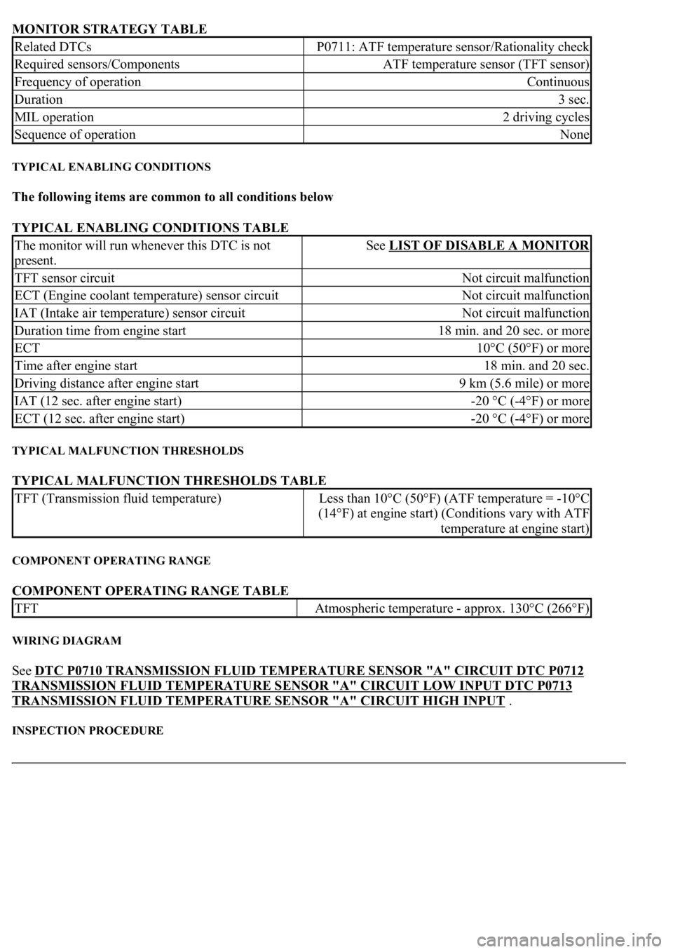
MONITOR STRATEGY TABLE
TYPICAL ENABLING CONDITIONS
The following items are common to all conditions below
TYPICAL ENABLING CONDITIONS TABLE
TYPICAL MALFUNCTION THRESHOLDS
TYPICAL MALFUNCTION THRESHOLDS TABLE
COMPONENT OPERATING RANGE
COMPONENT OPERATING RANGE TABLE
WIRING DIAGRAM
See DTC P0710 TRANSMISSION FLUID TEMPERATURE SENSOR "A" CIRCUIT DTC P0712
TRANSMISSION FLUID TEMPERATURE SENSOR "A" CIRCUIT LOW INPUT DTC P0713
TRANSMISSION FLUID TEMPERATURE SENSOR "A" CIRCUIT HIGH INPUT .
INSPECTION PROCEDURE
Related DTCsP0711: ATF temperature sensor/Rationality check
Required sensors/ComponentsATF temperature sensor (TFT sensor)
Frequency of operationContinuous
Duration3 sec.
MIL operation2 driving cycles
Sequence of operationNone
The monitor will run whenever this DTC is not
present.See LIST OF DISABLE A MONITOR
TFT sensor circuitNot circuit malfunction
ECT (Engine coolant temperature) sensor circuitNot circuit malfunction
IAT (Intake air temperature) sensor circuitNot circuit malfunction
Duration time from engine start18 min. and 20 sec. or more
ECT10°C (50°F) or more
Time after engine start18 min. and 20 sec.
Driving distance after engine start9 km (5.6 mile) or more
IAT (12 sec. after engine start)-20 °C (-4°F) or more
ECT (12 sec. after engine start)-20 °C (-4°F) or more
TFT (Transmission fluid temperature)Less than 10°C (50°F) (ATF temperature = -10°C
(14°F) at engine start) (Conditions vary with ATF
temperature at engine start)
TFTAtmospheric temperature - approx. 130°C (266°F)
Page 2759 of 4500
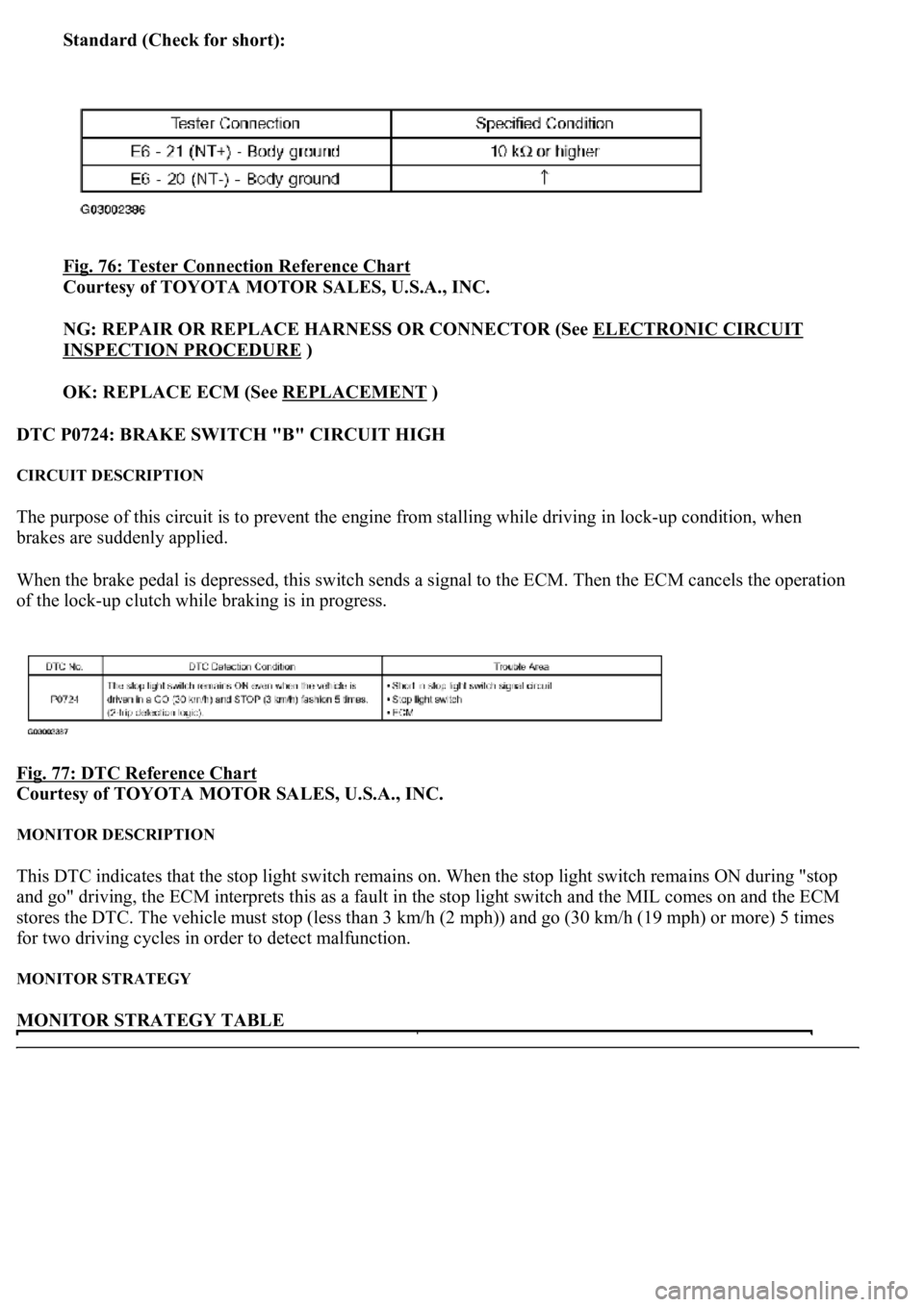
Standard (Check for short):
Fig. 76: Tester Connection Reference Chart
Courtesy of TOYOTA MOTOR SALES, U.S.A., INC.
NG: REPAIR OR REPLACE HARNESS OR CONNECTOR (See ELECTRONIC CIRCUIT
INSPECTION PROCEDURE )
OK: REPLACE ECM (See REPLACEMENT
)
DTC P0724: BRAKE SWITCH "B" CIRCUIT HIGH
CIRCUIT DESCRIPTION
The purpose of this circuit is to prevent the engine from stalling while driving in lock-up condition, when
brakes are suddenly applied.
When the brake pedal is depressed, this switch sends a signal to the ECM. Then the ECM cancels the operation
of the lock-up clutch while braking is in progress.
Fig. 77: DTC Reference Chart
Courtesy of TOYOTA MOTOR SALES, U.S.A., INC.
MONITOR DESCRIPTION
This DTC indicates that the stop light switch remains on. When the stop light switch remains ON during "stop
and go" driving, the ECM interprets this as a fault in the stop light switch and the MIL comes on and the ECM
stores the DTC. The vehicle must stop (less than 3 km/h (2 mph)) and go (30 km/h (19 mph) or more) 5 times
for two driving cycles in order to detect malfunction.
MONITOR STRATEGY
MONITOR STRATEGY TABLE
Page 2774 of 4500
Fig. 93: Tester Connection Reference Chart
Courtesy of TOYOTA MOTOR SALES, U.S.A., INC.
NG: REPAIR OR REPLACE HARNESS OR CONNECTOR (See ELECTRONIC CIRCUIT
INSPECTION PROCEDURE )
OK: REPLACE ECM (See REPLACEMENT
)
3.INSPECT SHIFT SOLENOID VALVE (SL1)
a. Remove the shift solenoid valve SL1.
b. Measure the resistance according to the value(s) in the table below.
Standard:
SHIFT SOLENOID VALVE (SL1) - RESISTANCE TABLE
c. Connect the positive (+) lead with a 21 W bulb to terminal 2 and the negative (-) lead to terminal 1
of the solenoid valve connector, then check the movement of the valve.
OK:
The solenoid makes an operating noise.
Tester ConnectionSpecified Condition 20°C (68°F)
1 - 25.0 to 5.6 ohms
Page 2816 of 4500
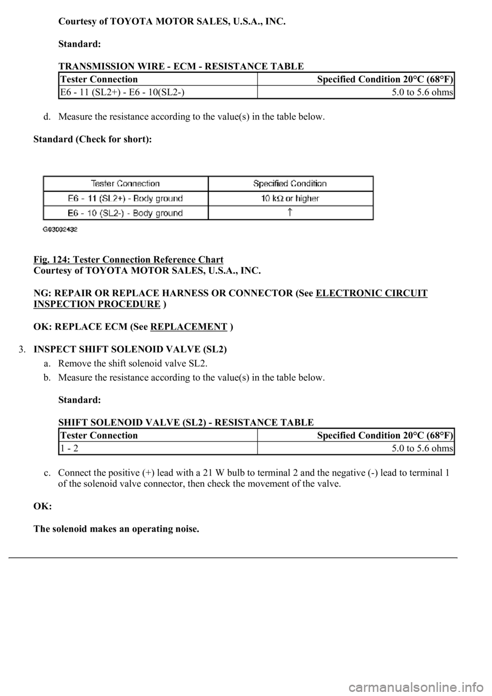
Courtesy of TOYOTA MOTOR SALES, U.S.A., INC.
Standard:
TRANSMISSION WIRE - ECM - RESISTANCE TABLE
d. Measure the resistance according to the value(s) in the table below.
Standard (Check for short):
Fig. 124: Tester Connection Reference Chart
Courtesy of TOYOTA MOTOR SALES, U.S.A., INC.
NG: REPAIR OR REPLACE HARNESS OR CONNECTOR (See ELECTRONIC CIRCUIT
INSPECTION PROCEDURE )
OK: REPLACE ECM (See REPLACEMENT
)
3.INSPECT SHIFT SOLENOID VALVE (SL2)
a. Remove the shift solenoid valve SL2.
b. Measure the resistance according to the value(s) in the table below.
Standard:
SHIFT SOLENOID VALVE (SL2) - RESISTANCE TABLE
c. Connect the positive (+) lead with a 21 W bulb to terminal 2 and the negative (-) lead to terminal 1
of the solenoid valve connector, then check the movement of the valve.
OK:
The solenoid makes an operating noise.
Tester ConnectionSpecified Condition 20°C (68°F)
E6 - 11 (SL2+) - E6 - 10(SL2-)5.0 to 5.6 ohms
Tester ConnectionSpecified Condition 20°C (68°F)
1 - 25.0 to 5.6 ohms
Page 2826 of 4500
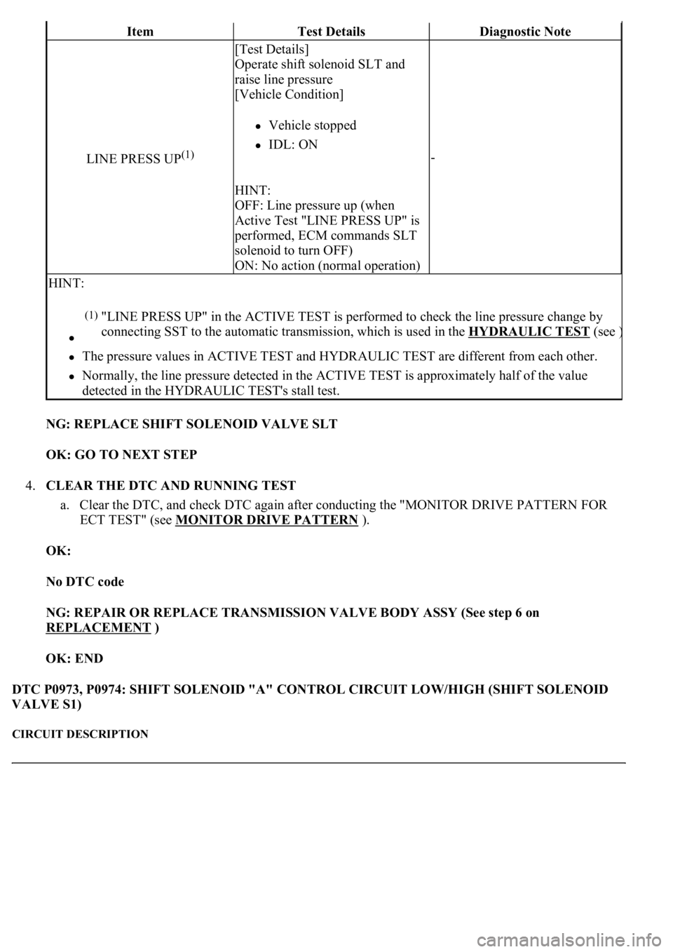
NG: REPLACE SHIFT SOLENOID VALVE SLT
OK: GO TO NEXT STEP
4.CLEAR THE DTC AND RUNNING TEST
a. Clear the DTC, and check DTC again after conducting the "MONITOR DRIVE PATTERN FOR
ECT TEST" (see MONITOR DRIVE PATTERN
).
OK:
No DTC code
NG: REPAIR OR REPLACE TRANSMISSION VALVE BODY ASSY (See step 6 on
REPLACEMENT
)
OK: END
DTC P0973, P0974: SHIFT SOLENOID "A" CONTROL CIRCUIT LOW/HIGH (SHIFT SOLENOID
VALVE S1)
CIRCUIT DESCRIPTION
ItemTest DetailsDiagnostic Note
LINE PRESS UP(1)
[Test Details]
Operate shift solenoid SLT and
raise line pressure
[Vehicle Condition]
Vehicle stopped
IDL: ON
HINT:
OFF: Line pressure up (when
Active Test "LINE PRESS UP" is
performed, ECM commands SLT
solenoid to turn OFF)
ON: No action (normal operation)
-
HINT:
The pressure values in ACTIVE TEST and HYDRAULIC TEST are different from each other.
Normally, the line pressure detected in the ACTIVE TEST is approximately half of the value
detected in the HYDRAULIC TEST's stall test.
(1)"LINE PRESS UP" in the ACTIVE TEST is performed to check the line pressure change by
connecting SST to the automatic transmission, which is used in the HYDRAULIC TEST
(see )
Page 2830 of 4500
c. Measure the resistance according to the value(s) in the table below.
Fig. 136: Disconnecting Connector From ECM
Courtesy of TOYOTA MOTOR SALES, U.S.A., INC.
Standard:
TRANSMISSION WIRE - ECM - RESISTANCE TABLE
NG: REPAIR OR REPLACE HARNESS OR CONNECTOR (See ELECTRONIC CIRCUIT
INSPECTION PROCEDURE )
OK: REPLACE ECM (See REPLACEMENT
)
3.INSPECT SHIFT SOLENOID VALVE (S1)
a. Remove the shift solenoid valve S1.
b. Measure the resistance according to the value(s) in the table below.
Standard:
Tester ConnectionSpecified Condition 20°C (68°F)
E6 - 19 (S1) - Body ground11 to 15ohms