Page 4314 of 4500
Fig. 124: Removing Air Conditioning Amplifier Assy
Courtesy of TOYOTA MOTOR SALES, U.S.A., INC.
31.WIRING AIR INDICATOR HARNESS SUB-ASSY NO. 2
32.REMOVE BLOWER RESISTOR
a. Remove the screw and blower resister.
Page 4317 of 4500
Fig. 127: Removing Evaporator Sub-Assy (Rear)
Courtesy of TOYOTA MOTOR SALES, U.S.A., INC.
35.REMOVE REAR COOLING UNIT EXPANSION VALVE
a. Using a hexagon wrench 5 mm (0.20 in.), remove the 2 hexagon bolts, air conditioning tube assy
and rear cooling unit expansion valve.
b. Remove the 4 O-rings from the rear cooling unit expansion valve.
Page 4318 of 4500
Fig. 128: Removing Rear Cooling Unit Expansion Valve
Courtesy of TOYOTA MOTOR SALES, U.S.A., INC.
36.INSTALL REAR COOLING UNIT EXPANSION VALVE
a. Sufficiently apply compressor oil to 4 new O-rings and fitting surface of the cooler expansion
valve.
Compressor oil: ND-OIL 8 or equivalent
b. Install the 4 O-rings on the rear cooling unit expansion valve.
c. Using a hexagon wrench 5 mm (0.20 in.), install the rear cooling unit expansion valve, air
conditioning tube assy with the 2 hexagon bolts.
Torque: 3.5 N.m (36 kgf.cm, 31 in.lbf)
Page 4402 of 4500
Fig. 3: Inspecting Intake Air Control Function
Courtesy of TOYOTA MOTOR SALES, U.S.A., INC.
a. Remove the V-bank cover.
b. Connect the hand-held tester (with CAN VIM) to the DLC3.
c. Perform the ACTIVE TEST, and then check that the actuator rod operates.
d. Start the engine.
e. Check that the VSV for IAC valve in ON (seal) under these conditions.
Depressing the accelerator pedal to a throttle valve opening angle of 60 degrees.
Racing the engine above 4,700 rpm.
f. Check that the VSV for IAC valve is OFF (vent) under these conditions.
The engine is idling.
Releasing the accelerator pedal while under the 2 conditions in step (e).
If the result is not as specified, inspect the IAC valve, vacuum tank and VSV for normal operation.
Replace malfunctioning parts as necessary.
INSPECTION
1.INSPECT INTAKE AIR CONTROL VALVE ACTUATOR
a. Connect the MITYVAC (han
d-held vacuum pump) to the actuator.
Page 4406 of 4500
VACUUM SWITCHING VALVE ASSY FOR IAC VALVE
If the resistance is not as specified, replace the VSV assy.
b. Check the VSV operation.
1. Check that air flows from port E to the filter.
If the result is not as specified, replace the VSV assy.
Fig. 7: Checking Air Flows From Port E To Filter
Courtesy of TOYOTA MOTOR SALES, U.S.A., INC.
2. Apply battery positive voltage across the terminals.
3. Check that air flows from port E to port F.
Tester ConnectionSpecified Condition
1 - 233 to 39 ohms at 20°C (68°F)
1 - Body ground, 2 - Body ground10 kohms or higher
Page 4425 of 4500

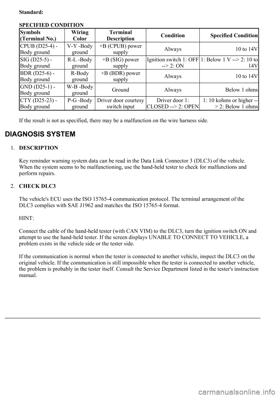
Standard:
SPECIFIED CONDITION
If the result is not as specified, there may be a malfunction on the wire harness side.
1.DESCRIPTION
Key reminder warning system data can be read in the Data Link Connector 3 (DLC3) of the vehicle.
When the system seems to be malfunctioning, use the hand-held tester to check for malfunctions and
perform repairs.
2.CHECK DLC3
The vehicle's ECU uses the ISO 15765-4 communication protocol. The terminal arrangement of the
DLC3 complies with SAE J1962 and matches the ISO 15765-4 format.
HINT:
Connect the cable of the hand-held tester (with CAN VIM) to the DLC3, turn the ignition switch ON and
attempt to use the hand-held tester. If the screen displays UNABLE TO CONNECT TO VEHICLE, a
problem exists in the vehicle side or the tester side.
If the communication is normal when the tester is connected to another vehicle, inspect the DLC3 on the
original vehicle. If the communication is still impossible when the tester is connected to another vehicle,
the problem is probably in the tester itself. Consult the Service Department listed in the tester's instruction
manual.
Symbols
(Terminal No.)Wiring
ColorTerminal
DescriptionConditionSpecified Condition
CPUB (D25-4) -
Body groundV-Y -Body
ground+B (CPUB) power
supplyAlways10 to 14V
SIG (D25-5) -
Body groundR-L -Body
ground+B (SIG) power
supplyIgnition switch 1: OFF
--> 2: ON1: Below 1 V --> 2: 10 to
14V
BDR (D25-6) -
Body groundR-Body
ground+B (BDR) power
supplyAlways10 to 14V
GND (D25-1) -
Body groundW-B -Body
groundGroundAlwaysBelow 1 ohms
CTY (D25-23) -
Body groundP-G -Body
groundDriver door courtesy
switch inputDriver door 1:
CLOSED --> 2: OPEN1: 10 kohms or higher --
> 2: Below 1 ohms
Page 4431 of 4500
3.CHECK WIRE HARNESS (DRIVER DOOR ECU - BATTERY AND BODY GROUND)
a. Disconnect the D25 ECU connector.
b. Measure the voltage and resistance of the wire harness side connector.
Standard:
Fig. 16: Identifying Terminals Of Driver Door ECU
Courtesy of TOYOTA MOTOR SALES, U.S.A., INC.
SPECIFIED CONDITION
NG: REPAIR OR REPLACE HARNESS AND CONNECTOR
OK: PROCEED TO NEXT CIRCUIT INSPECTION SHOWN ON PROBLEM SYMPTOMS
TABLE
Tester connectionConditionSpecified condition
D25-1 (GND) - Body groundAlwaysBelow 1 ohms
D25-4 (CPUB) - Body groundAlways10 to 14V
D25-6 (BDR)- Body groundAlways10 to 14V
D25-5 (SIG) Body groundIgnition switch ON10 to 14V