Page 1680 of 4500
Fig. 61: Identifying PJ Passenger Side J/B Connector Terminals
Courtesy of TOYOTA MOTOR SALES, U.S.A., INC.
NG: Go to step 5
OK: REPAIR OR REPLACE HARNESS AND CONNECTOR (PASSENGER SIDE J/B -
CLIMATE CONTROL BLOWER (CLIMATE CONTROL ECU))
5.CHECK WIRE HARNESS (PASSENGER SIDE J/B - BODY GROUND
a. Disconnect the PA and PE J/B connectors.
b. Measure the voltage of the wire harness side connectors.
Tester ConnectionConditionSpecified Condition
PJ-9 - Body groundIgnition switch ON10 to 14 V
Page 1684 of 4500
NG: REPAIR OR REPLACE HARNESS AND CONNECTOR
OK: Go to next step
7.INSPECT RELAY (Marking: P-IG1)
a. Remove the P-IG1 relay from the passenger side J/B.
b. Measure the resistance of the relay.
Standard:
TESTER CONNECTION AND SPECIFIED CONDITION
Fig. 64: Identifying P
-IG1 Relay Terminals And Circuit
Courtesy of TOYOTA MOTOR SALES, U.S.A., INC.
NG: REPAIR OR REPLACE HARNESS AND CONNECTOR
OK: REPLACE DRIVER SIDE JUNCTION BLOCK
Tester ConnectionSpecified Condition
3 - 510 kohms or higher
3 - 5Below 1 ohms (when battery voltage is applied to terminal 1 and 2)
Page 1688 of 4500
Rear RH
TESTER CONNECTION AND SPECIFIED CONDITION - REAR RH
Fig. 67: Identifying Seat Climate Control Blower Connector Terminals
Courtesy of TOYOTA MOTOR SALES, U.S.A., INC.
NG: REPAIR OR REPLACE HARNESS AND CONNECTOR
OK: Go to next step
4.CHECK WIRE HARNESS (SEAT CLIMATE CONTROL BLOWER (CLIMATE CONTROL
ECU) - BODY GROUND)
a. Disconnect the C27 or C29 blower connector.
b. Measure the resistance of the wire harness side connector.
Tester ConnectionSpecified Condition
C29-11 (GND) - Body groundBelow 1 ohms
Page 1691 of 4500
Fig. 69: Identifying LC Luggage Room J/B Connector Terminals
Courtesy of TOYOTA MOTOR SALES, U.S.A., INC.
NG: Go to step 6
OK: REPAIR OR REPLACE HARNESS AND CONNECTOR (LUGGAGE ROOM J/B ASSY -
CLIMATE CONTROL BLOWER (CLIMATE CONTROL ECU))
6.CHECK WIRE HARNESS (LUGGAGE ROOM J/B ASSY - BATTERY)
a. Disconnect the LL J/B connector.
b. Measure the voltage of the wire harness side connector.
Standard:
TESTER CONNECTION AND SPECIFIED CONDITION
Tester ConnectionSpecified Condition
LL-1 - Body ground10 to 14 V
Page 1692 of 4500
Fig. 70: Identifying LL Luggage Room J/B Ground Harness
Courtesy of TOYOTA MOTOR SALES, U.S.A., INC.
NG: REPAIR OR REPLACE HARNESS AND CONNECTOR
OK: Go to next step
7.CHECK WIRE HARNESS (LUGGAGE ROOM J/B ASSY - BODY GROUND)
a. Disconnect the LA J/B connector.
b. Measure the resistance of the wire harness side connector.
Standard:
TESTER CONNECTION AND SPECIFIED CONDITION
Page 1693 of 4500
Fig. 71: Identifying LA Luggage Room J/B Connector Terminals
Courtesy of TOYOTA MOTOR SALES, U.S.A., INC.
NG: REPAIR OR REPLACE HARNESS AND CONNECTOR
OK: Go to next step
8.INSPECT RELAY (Marking: L-IG1)
a. Remove the L-IG1 relay from the luggage room J/B.
b. Measure the resistance of the relay.
Standard:
Tester ConnectionSpecified Condition
LA-5 - Body groundBelow 1 ohms
Page 1700 of 4500

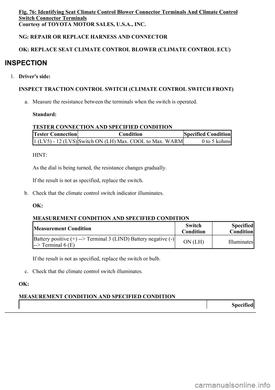
Fig. 76: Identifying Seat Climate Control Blower Connector Terminals And Climate Control
Switch Connector Terminals
Courtesy of TOYOTA MOTOR SALES, U.S.A., INC.
NG: REPAIR OR REPLACE HARNESS AND CONNECTOR
OK: REPLACE SEAT CLIMATE CONTROL BLOWER (CLIMATE CONTROL ECU)
1.Driver's side:
INSPECT TRACTION CONTROL SWITCH (CLIMATE CONTROL SWITCH FRONT)
a. Measure the resistance between the terminals when the switch is operated.
Standard:
TESTER CONNECTION AND SPECIFIED CONDITION
HINT:
As the dial is being turned, the resistance changes gradually.
If the result is not as specified, replace the switch.
b. Check that the climate control switch indicator illuminates.
OK:
MEASUREMENT CONDITION AND SPECIFIED CONDITION
If the result is not as specified, replace the switch or bulb.
c. Check that the climate control switch illuminates.
OK:
MEASUREMENT CONDITION AND SPECIFIED CONDITION
Tester ConnectionConditionSpecified Condition
1 (LV5) - 12 (LVS)Switch ON (LH) Max. COOL to Max. WARM0 to 5 kohms
Measurement ConditionSwitch
ConditionSpecified
Condition
Battery positive (+) --> Terminal 3 (LIND) Battery negative (-)
--> Terminal 6 (E)ON (LH)Illuminates
Specified
Page 1776 of 4500

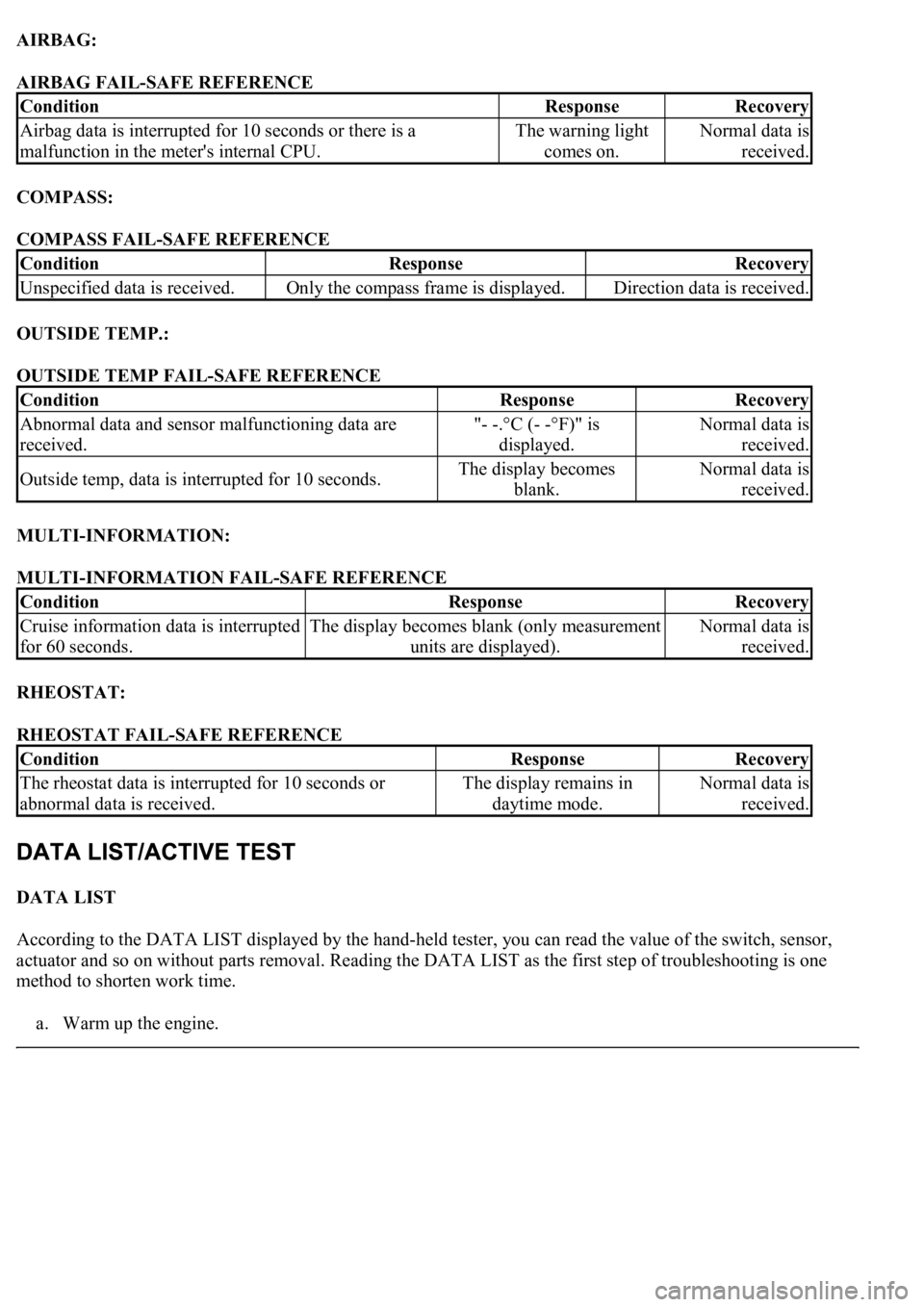
AIRBAG:
AIRBAG FAIL-SAFE REFERENCE
COMPASS:
COMPASS FAIL-SAFE REFERENCE
OUTSIDE TEMP.:
OUTSIDE TEMP FAIL-SAFE REFERENCE
MULTI-INFORMATION:
MULTI-INFORMATION FAIL-SAFE REFERENCE
RHEOSTAT:
RHEOSTAT FAIL-SAFE REFERENCE
DATA LIST
According to the DATA LIST displayed by the hand-held tester, you can read the value of the switch, sensor,
actuator and so on without parts removal. Reading the DATA LIST as the first step of troubleshooting is one
method to shorten work time.
a. Warm up the en
gine.
ConditionResponseRecovery
Airbag data is interrupted for 10 seconds or there is a
malfunction in the meter's internal CPU.The warning light
comes on.Normal data is
received.
ConditionResponseRecovery
Unspecified data is received.Only the compass frame is displayed.Direction data is received.
ConditionResponseRecovery
Abnormal data and sensor malfunctioning data are
received."- -.°C (- -°F)" is
displayed.Normal data is
received.
Outside temp, data is interrupted for 10 seconds.The display becomes
blank.Normal data is
received.
ConditionResponseRecovery
Cruise information data is interrupted
for 60 seconds.The display becomes blank (only measurement
units are displayed).Normal data is
received.
ConditionResponseRecovery
<0037004b004800030055004b004800520056005700440057000300470044005700440003004c00560003004c005100570048005500550058005300570048004700030049005200550003001400130003005600480046005200510047005600030052005500
03[
abnormal data is received.The display remains in
daytime mode.Normal data is
received.