Page 1577 of 4500
Fig. 66: Identifying C17 Connector Terminals
Courtesy of TOYOTA MOTOR SALES, U.S.A., INC.
NG: REPAIR OR REPLACE HARNESS OR CONNECTOR (CLEARANCE WARNING ECU
ASSY - BODY GROUND)
OK: Go To Next Step.
4.INSPECT OUTER MIRROR SWITCH ASSY
a. Disconnect the O5 connector from the clearance sonar main switch.
b. Measure the resistance according to the value (s) in the table below.
Standard:
TESTER CONNECTION SPECIFIED CONDITION
Tester connection (Symbols)ConditionSpecified condition
O5-3 - O5-4Clearance sonar main switch off10 kohms or higher
O5-3 - O5-4Clearance sonar main switch onBelow 1 ohms
Page 1600 of 4500
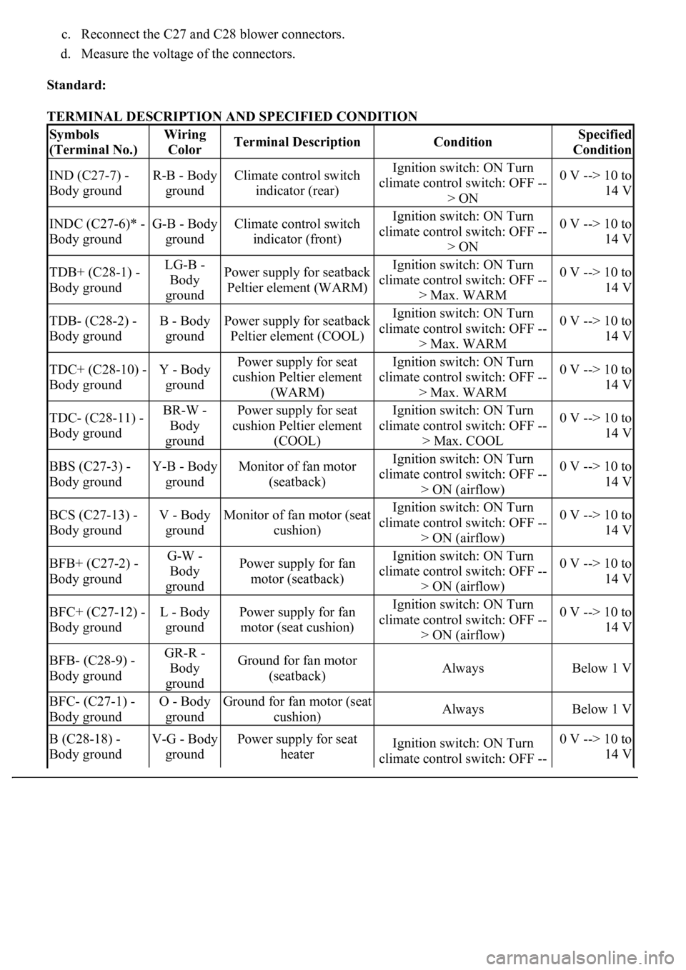
c. Reconnect the C27 and C28 blower connectors.
d. Measure the voltage of the connectors.
Standard:
TERMINAL DESCRIPTION AND SPECIFIED CONDITION
Symbols
(Terminal No.)Wiring
ColorTerminal DescriptionConditionSpecified
Condition
IND (C27-7) -
Body groundR-B - Body
groundClimate control switch
indicator (rear)Ignition switch: ON Turn
climate control switch: OFF --
> ON0 V --> 10 to
14 V
INDC (C27-6)* -
Body groundG-B - Body
groundClimate control switch
indicator (front)Ignition switch: ON Turn
climate control switch: OFF --
> ON0 V --> 10 to
14 V
TDB+ (C28-1) -
Body groundLG-B -
Body
groundPower supply for seatback
Peltier element (WARM)Ignition switch: ON Turn
climate control switch: OFF --
> Max. WARM0 V --> 10 to
14 V
TDB- (C28-2) -
Body groundB - Body
groundPower supply for seatback
Peltier element (COOL)Ignition switch: ON Turn
climate control switch: OFF --
> Max. WARM0 V --> 10 to
14 V
TDC+ (C28-10) -
Body groundY - Body
groundPower supply for seat
cushion Peltier element
(WARM)Ignition switch: ON Turn
climate control switch: OFF --
> Max. WARM0 V --> 10 to
14 V
TDC- (C28-11) -
Body groundBR-W -
Body
groundPower supply for seat
cushion Peltier element
(COOL)Ignition switch: ON Turn
climate control switch: OFF --
> Max. COOL0 V --> 10 to
14 V
BBS (C27-3) -
Body groundY-B - Body
groundMonitor of fan motor
(seatback)Ignition switch: ON Turn
climate control switch: OFF --
> ON (airflow)0 V --> 10 to
14 V
BCS (C27-13) -
Body groundV - Body
groundMonitor of fan motor (seat
cushion)Ignition switch: ON Turn
climate control switch: OFF --
> ON (airflow)0 V --> 10 to
14 V
BFB+ (C27-2) -
Body groundG-W -
Body
groundPower supply for fan
motor (seatback)Ignition switch: ON Turn
climate control switch: OFF --
> ON (airflow)0 V --> 10 to
14 V
BFC+ (C27-12) -
Body groundL - Body
groundPower supply for fan
motor (seat cushion)Ignition switch: ON Turn
climate control switch: OFF --
> ON (airflow)0 V --> 10 to
14 V
BFB- (C28-9) -
Body groundGR-R -
Body
groundGround for fan motor
(seatback)AlwaysBelow 1 V
BFC- (C27-1) -
Body groundO - Body
groundGround for fan motor (seat
cushion)AlwaysBelow 1 V
B (C28-18) -
Body groundV-G - Body
groundPower supply for seat
heaterIgnition switch: ON Turn
climate control switch: OFF --0 V --> 10 to
14 V
Page 1624 of 4500
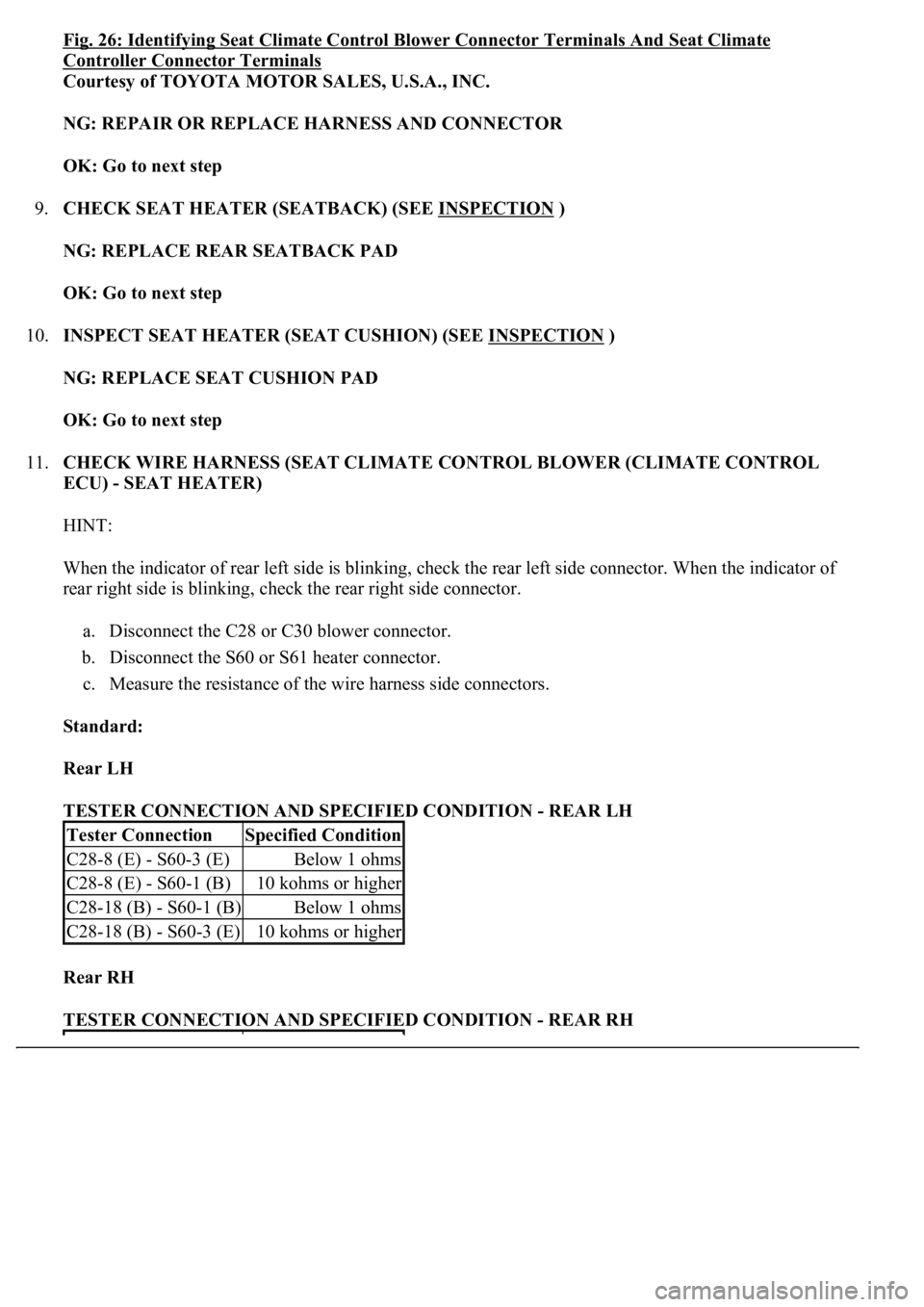
Fig. 26: Identifying Seat Climate Control Blower Connector Terminals And Seat Climate
Controller Connector Terminals
Courtesy of TOYOTA MOTOR SALES, U.S.A., INC.
NG: REPAIR OR REPLACE HARNESS AND CONNECTOR
OK: Go to next step
9.CHECK SEAT HEATER (SEATBACK) (SEE INSPECTION
)
NG: REPLACE REAR SEATBACK PAD
OK: Go to next step
10.INSPECT SEAT HEATER (SEAT CUSHION) (SEE INSPECTION
)
NG: REPLACE SEAT CUSHION PAD
OK: Go to next step
11.CHECK WIRE HARNESS (SEAT CLIMATE CONTROL BLOWER (CLIMATE CONTROL
ECU) - SEAT HEATER)
HINT:
When the indicator of rear left side is blinking, check the rear left side connector. When the indicator of
rear right side is blinking, check the rear right side connector.
a. Disconnect the C28 or C30 blower connector.
b. Disconnect the S60 or S61 heater connector.
c. Measure the resistance of the wire harness side connectors.
Standard:
Rear LH
TESTER CONNECTION AND SPECIFIED CONDITION - REAR LH
Rear RH
TESTER CONNECTION AND SPECIFIED CONDITION - REAR RH
Tester ConnectionSpecified Condition
C28-8 (E) - S60-3 (E)Below 1 ohms
C28-8 (E) - S60-1 (B)10 kohms or higher
C28-18 (B) - S60-1 (B)Below 1 ohms
C28-18 (B) - S60-3 (E)10 kohms or higher
Page 1627 of 4500
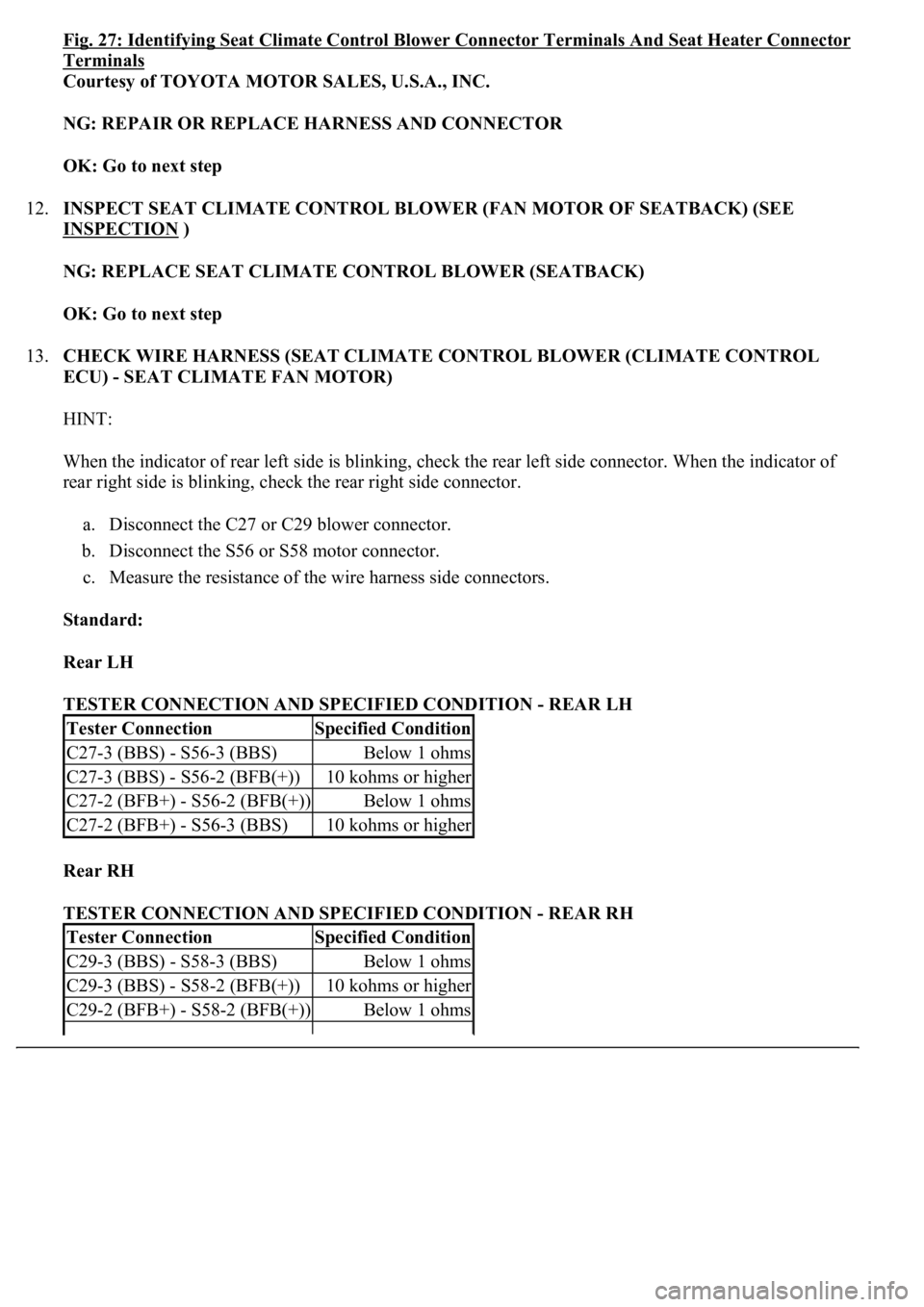
Fig. 27: Identifying Seat Climate Control Blower Connector Terminals And Seat Heater Connector
Terminals
Courtesy of TOYOTA MOTOR SALES, U.S.A., INC.
NG: REPAIR OR REPLACE HARNESS AND CONNECTOR
OK: Go to next step
12.INSPECT SEAT CLIMATE CONTROL BLOWER (FAN MOTOR OF SEATBACK) (SEE
INSPECTION
)
NG: REPLACE SEAT CLIMATE CONTROL BLOWER (SEATBACK)
OK: Go to next step
13.CHECK WIRE HARNESS (SEAT CLIMATE CONTROL BLOWER (CLIMATE CONTROL
ECU) - SEAT CLIMATE FAN MOTOR)
HINT:
When the indicator of rear left side is blinking, check the rear left side connector. When the indicator of
rear right side is blinking, check the rear right side connector.
a. Disconnect the C27 or C29 blower connector.
b. Disconnect the S56 or S58 motor connector.
c. Measure the resistance of the wire harness side connectors.
Standard:
Rear LH
TESTER CONNECTION AND SPECIFIED CONDITION - REAR LH
Rear RH
TESTER CONNECTION AND SPECIFIED CONDITION - REAR RH
Tester ConnectionSpecified Condition
C27-3 (BBS) - S56-3 (BBS)Below 1 ohms
C27-3 (BBS) - S56-2 (BFB(+))10 kohms or higher
C27-2 (BFB+) - S56-2 (BFB(+))Below 1 ohms
C27-2 (BFB+) - S56-3 (BBS)10 kohms or higher
Tester ConnectionSpecified Condition
C29-3 (BBS) - S58-3 (BBS)Below 1 ohms
C29-3 (BBS) - S58-2 (BFB(+))10 kohms or higher
C29-2 (BFB+) - S58-2 (BFB(+))Below 1 ohms
Page 1645 of 4500
Fig. 38: Identifying Seat Climate Control Blower Connector Terminals
Courtesy of TOYOTA MOTOR SALES, U.S.A., INC.
NG: REPAIR OR REPLACE HARNESS AND CONNECTOR
OK: Go to next step
10.CHECK WIRE HARNESS (SEAT CLIMATE CONTROL BLOWER (CLIMATE CONTROL
ECU) - BODY GROUND)
HINT:
When the rear LH indicator is blinking, check the rear LH side connector. When the rear RH indicator is
blinking, check the rear right RH side connector.
a. Measure the voltage of the wire harness side connector.
Standard:
Rear LH
TESTER CONNECTION AND SPECIFIED CONDITION - REAR LH
Rear RH
TESTER CONNECTION AND SPECIFIED CONDITION - REAR RH
Tester ConnectionConditionSpecified Condition
C27-18 (V5) - Body groundIgnition switch ON, Climate control switch ON5 V
Tester ConnectionConditionSpecified Condition
C29-18 (V5) - Body groundIgnition switch ON, Climate control switch ON5 V
Page 1649 of 4500
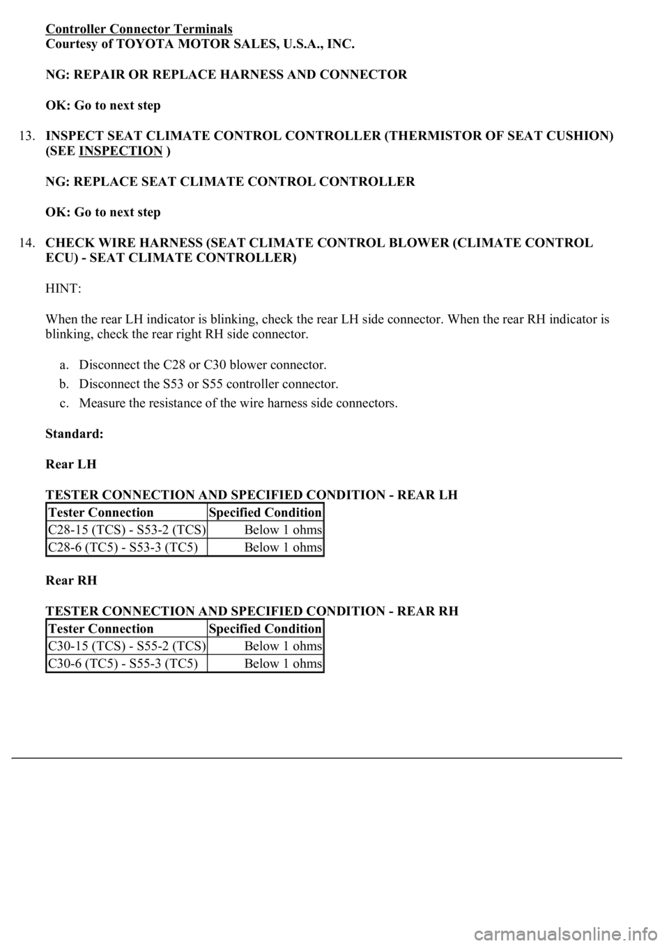
Controller Connector Terminals
Courtesy of TOYOTA MOTOR SALES, U.S.A., INC.
NG: REPAIR OR REPLACE HARNESS AND CONNECTOR
OK: Go to next step
13.INSPECT SEAT CLIMATE CONTROL CONTROLLER (THERMISTOR OF SEAT CUSHION)
(SEE INSPECTION
)
NG: REPLACE SEAT CLIMATE CONTROL CONTROLLER
OK: Go to next step
14.CHECK WIRE HARNESS (SEAT CLIMATE CONTROL BLOWER (CLIMATE CONTROL
ECU) - SEAT CLIMATE CONTROLLER)
HINT:
When the rear LH indicator is blinking, check the rear LH side connector. When the rear RH indicator is
blinking, check the rear right RH side connector.
a. Disconnect the C28 or C30 blower connector.
b. Disconnect the S53 or S55 controller connector.
c. Measure the resistance of the wire harness side connectors.
Standard:
Rear LH
TESTER CONNECTION AND SPECIFIED CONDITION - REAR LH
Rear RH
TESTER CONNECTION AND SPECIFIED CONDITION - REAR RH
Tester ConnectionSpecified Condition
C28-15 (TCS) - S53-2 (TCS)Below 1 ohms
C28-6 (TC5) - S53-3 (TC5)Below 1 ohms
Tester ConnectionSpecified Condition
C30-15 (TCS) - S55-2 (TCS)Below 1 ohms
C30-6 (TC5) - S55-3 (TC5)Below 1 ohms
Page 1651 of 4500
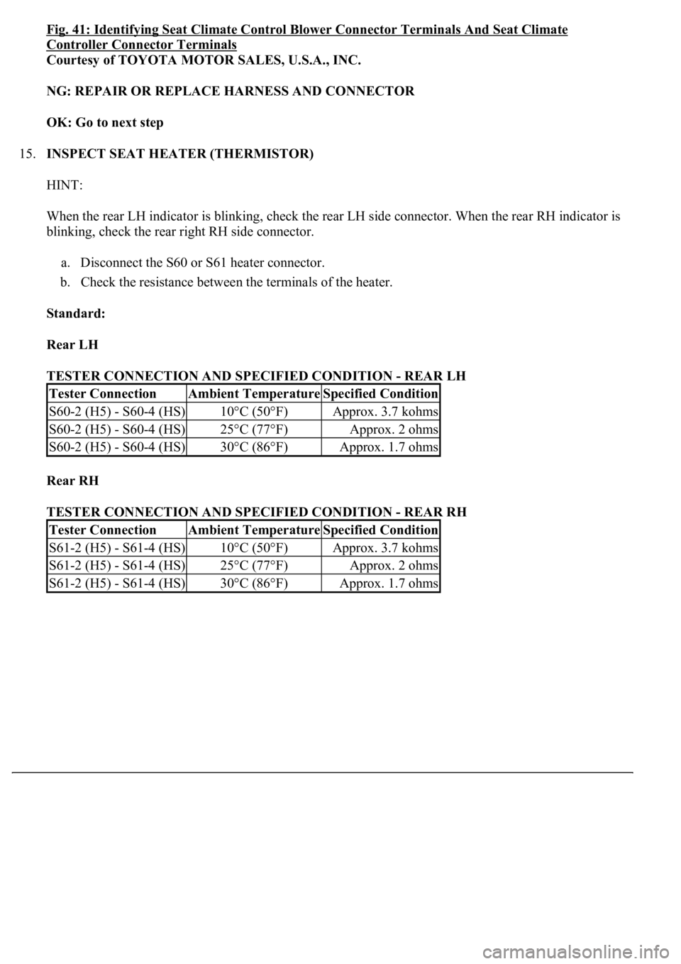
Fig. 41: Identifying Seat Climate Control Blower Connector Terminals And Seat Climate
Controller Connector Terminals
Courtesy of TOYOTA MOTOR SALES, U.S.A., INC.
NG: REPAIR OR REPLACE HARNESS AND CONNECTOR
OK: Go to next step
15.INSPECT SEAT HEATER (THERMISTOR)
HINT:
When the rear LH indicator is blinking, check the rear LH side connector. When the rear RH indicator is
blinking, check the rear right RH side connector.
a. Disconnect the S60 or S61 heater connector.
b. Check the resistance between the terminals of the heater.
Standard:
Rear LH
TESTER CONNECTION AND SPECIFIED CONDITION - REAR LH
Rear RH
TESTER CONNECTION AND SPECIFIED CONDITION - REAR RH
Tester ConnectionAmbient TemperatureSpecified Condition
S60-2 (H5) - S60-4 (HS)10°C (50°F)Approx. 3.7 kohms
S60-2 (H5) - S60-4 (HS)25°C (77°F)Approx. 2 ohms
S60-2 (H5) - S60-4 (HS)30°C (86°F)Approx. 1.7 ohms
Tester ConnectionAmbient TemperatureSpecified Condition
S61-2 (H5) - S61-4 (HS)10°C (50°F)Approx. 3.7 kohms
S61-2 (H5) - S61-4 (HS)25°C (77°F)Approx. 2 ohms
S61-2 (H5) - S61-4 (HS)30°C (86°F)Approx. 1.7 ohms
Page 1660 of 4500
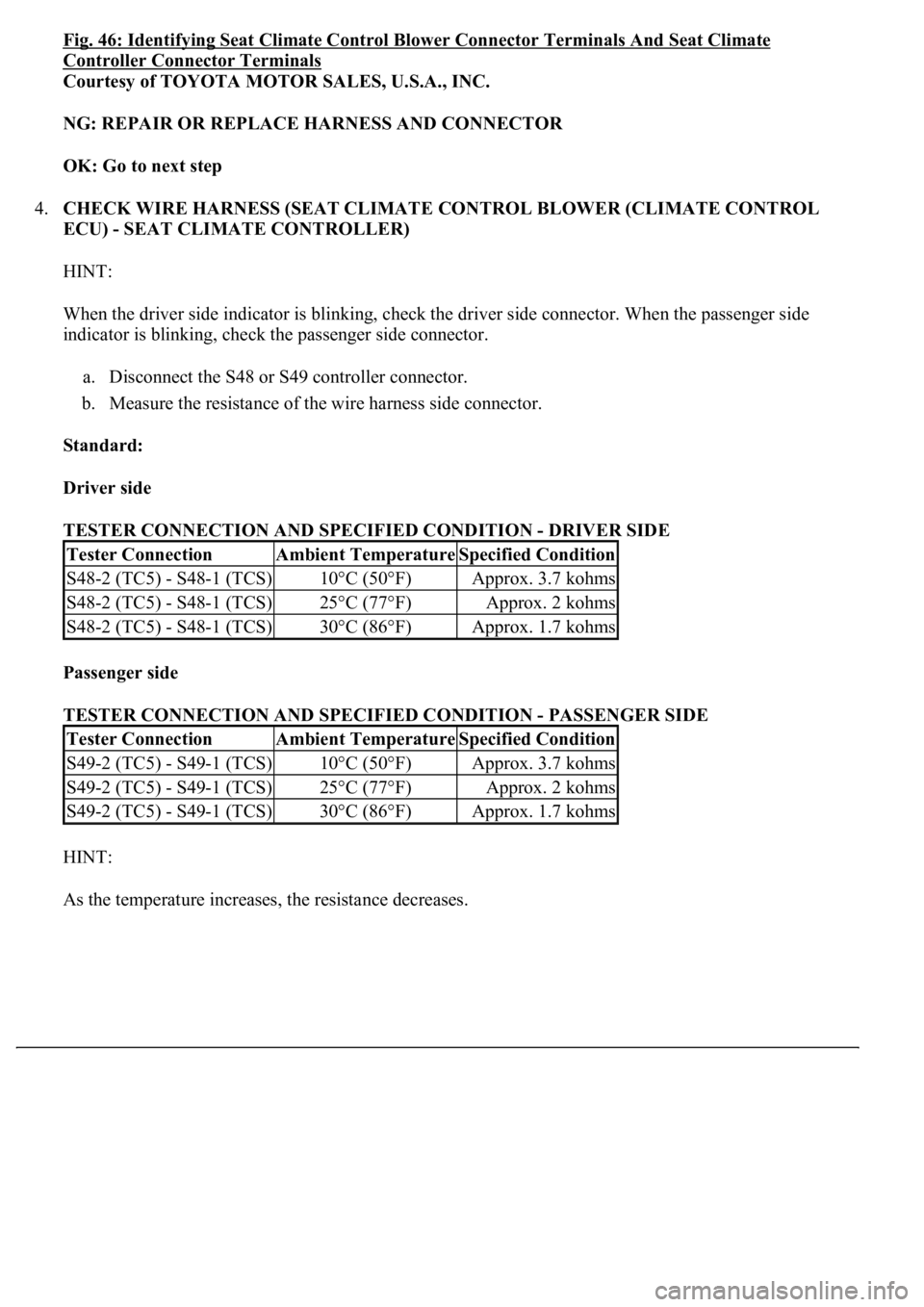
Fig. 46: Identifying Seat Climate Control Blower Connector Terminals And Seat Climate
Controller Connector Terminals
Courtesy of TOYOTA MOTOR SALES, U.S.A., INC.
NG: REPAIR OR REPLACE HARNESS AND CONNECTOR
OK: Go to next step
4.CHECK WIRE HARNESS (SEAT CLIMATE CONTROL BLOWER (CLIMATE CONTROL
ECU) - SEAT CLIMATE CONTROLLER)
HINT:
When the driver side indicator is blinking, check the driver side connector. When the passenger side
indicator is blinking, check the passenger side connector.
a. Disconnect the S48 or S49 controller connector.
b. Measure the resistance of the wire harness side connector.
Standard:
Driver side
TESTER CONNECTION AND SPECIFIED CONDITION - DRIVER SIDE
Passenger side
TESTER CONNECTION AND SPECIFIED CONDITION - PASSENGER SIDE
HINT:
As the temperature increases, the resistance decreases.
Tester ConnectionAmbient TemperatureSpecified Condition
S48-2 (TC5) - S48-1 (TCS)10°C (50°F)Approx. 3.7 kohms
S48-2 (TC5) - S48-1 (TCS)25°C (77°F)Approx. 2 kohms
S48-2 (TC5) - S48-1 (TCS)30°C (86°F)Approx. 1.7 kohms
Tester ConnectionAmbient TemperatureSpecified Condition
S49-2 (TC5) - S49-1 (TCS)10°C (50°F)Approx. 3.7 kohms
S49-2 (TC5) - S49-1 (TCS)25°C (77°F)Approx. 2 kohms
S49-2 (TC5) - S49-1 (TCS)30°C (86°F)Approx. 1.7 kohms