Page 2859 of 4500
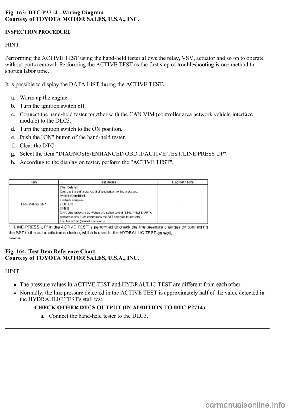
Fig. 163: DTC P2714 - Wiring Diagram
Courtesy of TOYOTA MOTOR SALES, U.S.A., INC.
INSPECTION PROCEDURE
HINT:
Performing the ACTIVE TEST using the hand-held tester allows the relay, VSV, actuator and so on to operate
without parts removal. Performing the ACTIVE TEST as the first step of troubleshooting is one method to
shorten labor time.
It is possible to display the DATA LIST during the ACTIVE TEST.
a. Warm up the engine.
b. Turn the ignition switch off.
c. Connect the hand-held tester together with the CAN VIM (controller area network vehicle interface
module) to the DLC3.
d. Turn the ignition switch to the ON position.
e. Push the "ON" button of the hand-held tester.
f. Clear the DTC.
g. Select the item "DIAGNOSIS/ENHANCED OBD II/ACTIVE TEST/LINE PRESS UP".
h. According to the display on tester, perform the "ACTIVE TEST".
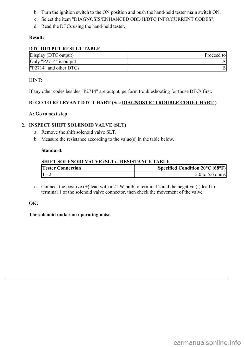
Fig. 164: Test Item Reference Chart
Courtesy of TOYOTA MOTOR SALES, U.S.A., INC.
HINT:
The pressure values in ACTIVE TEST and HYDRAULIC TEST are different from each other.
Normally, the line pressure detected in the ACTIVE TEST is approximately half of the value detected in
the HYDRAULIC TEST's stall test.
1.CHECK OTHER DTCS OUTPUT (IN ADDITION TO DTC P2714)
a. Connect the han
d-held tester to the DLC3.
Page 2860 of 4500
b. Turn the ignition switch to the ON position and push the hand-held tester main switch ON.
c. Select the item "DIAGNOSIS/ENHANCED OBD II/DTC INFO/CURRENT CODES".
d. Read the DTCs using the hand-held tester.
Result:
DTC OUTPUT RESULT TABLE
HINT:
If any other codes besides "P2714" are output, perform troubleshooting for those DTCs first.
B: GO TO RELEVANT DTC CHART (See DIAGNOSTIC TROUBLE CODE CHART
)
A: Go to next step
2.INSPECT SHIFT SOLENOID VALVE (SLT)
a. Remove the shift solenoid valve SLT.
b. Measure the resistance according to the value(s) in the table below.
Standard:
SHIFT SOLENOID VALVE (SLT) - RESISTANCE TABLE
c. Connect the positive (+) lead with a 21 W bulb to terminal 2 and the negative (-) lead to
terminal 1 of the solenoid valve connector, then check the movement of the valve.
OK:
The solenoid makes an operating noise.
Display (DTC output)Proceed to
Only "P2714" is outputA
"P2714" and other DTCsB
Tester ConnectionSpecified Condition 20°C (68°F)
1 - 25.0 to 5.6 ohms
Page 2873 of 4500
TYPICAL MALFUNCTION THRESHOLDS
Both of the following conditions are met: OFF malfunction (A) and (B)
OFF malfunction (A)
TYPICAL MALFUNCTION THRESHOLDS TABLE - OFF MALFUNCTION A
OFF malfunction (B)
TYPICAL MALFUNCTION THRESHOLDS TABLE - OFF MALFUNCTION B
ON malfunction
2 detections are necessary per driving cycle:
1st detection; temporary flag ON
2md detection; pending fault code ON
Vehicle speed must be under 10 km/h (6.2 mph) once before 2nd detection.
TYPICAL MALFUNCTION THRESHOLDS TABLE - ON MALFUNCTION
COMPONENT OPERATING RANGE
COMPONENT OPERATING RANGE TABLE
INSPECTION PROCEDURE
HINT:
Performing the ACTIVE TEST using the hand-held tester allows the relay, VSV, actuator and so on to operate
without parts removal. Performing the ACTIVE TEST as the first step of troubleshooting is one method to
shorten labor time.
It is possible to display the DATA LIST during the ACTIVE TEST.
Throttle valve opening angle9% or more
Vehicle speedLess than 60 km/h (37.3 mph)
Engine speed - Turbine speed (NE - NT)70 rpm or more
Engine speed - Turbine speed (NE - NT)Not 3.08 to 7.50
Engine speed - Turbine speed| (|NE - NT|)Less than 35 rpm
Speed sensor (NT)Input speed is equal to engine speed when lock-up
ON.
Page 2874 of 4500
a. Warm up the engine.
b. Turn the ignition switch off.
c. Connect the hand-held tester together with the CAN VIM (controller area network vehicle interface
module) to the DLC3.
d. Turn the ignition switch to the ON position.
e. Push the "ON" button of the hand-held tester.
f. Clear the DTC.
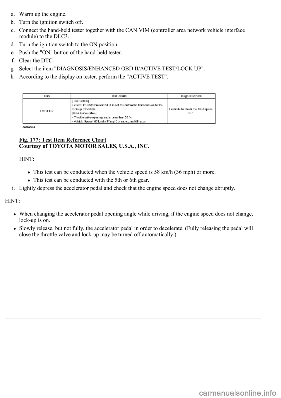
g. Select the item "DIAGNOSIS/ENHANCED OBD II/ACTIVE TEST/LOCK UP".
h. According to the display on tester, perform the "ACTIVE TEST".
Fig. 177: Test Item Reference Chart
Courtesy of TOYOTA MOTOR SALES, U.S.A., INC.
HINT:
This test can be conducted when the vehicle speed is 58 km/h (36 mph) or more.
This test can be conducted with the 5th or 6th gear.
i. Lightly depress the accelerator pedal and check that the engine speed does not change abruptly.
HINT:
When changing the accelerator pedal opening angle while driving, if the engine speed does not change,
lock-up is on.
Slowly release, but not fully, the accelerator pedal in order to decelerate. (Fully releasing the pedal will
close the throttle valve and loc
k-up may be turned off automatically.)
Page 2875 of 4500
Fig. 178: Identifying Accelerator Pedal Opening Angle Diagram
Courtesy of TOYOTA MOTOR SALES, U.S.A., INC.
1.CHECK OTHER DTCS OUTPUT (IN ADDITION TO DTC P2757)
a. Connect the hand-held tester to the DLC3.
b. Turn the ignition switch to the ON position and push the hand-held tester main switch ON.
c. Select the item "DIAGNOSIS/ENHANCED OBD II/DTC INFO/CURRENT CODES".
d. Read the DTCs using the hand-held tester.
Result:
DTC OUTPUT RESULT TABLE
HINT:
If any other codes besides "P2757" are output, perform troubleshooting for those DTCs first.
B: GO TO RELEVANT DTC CHART (See DIAGNOSTIC TROUBLE CODE CHART
)
A: Go to next step
2.INSPECT SHIFT SOLENOID VALVE (SLU)
a. Remove the shift solenoid valve SLU.
b. Measure the resistance according to the value(s) in the table below.
Display (DTC output)Proceed to
Only "P2757" is outputA
"P2757" and other DTCsB
Page 2982 of 4500
Torque: 5.5 N.m (55 kgf.cm, 48 in..lbf)
8.INSTALL ECM COVER
a. Install the ECM cover with the 3 bolts.
Torque: 5.0 N.m (51 kgf.cm, 44 in..lbf)
9.INSTALL ENGINE ROOM SIDE COVER
a. Install the engine room side cover with the 3 clips.
10.CONNECT BATTERY NEGATIVE TERMINAL
11.CONFIGURE ECM FOR OPTIONAL DYNAMIC RADAR/LASER CRUISE CONTROL
a. Be sure to perform the following procedures after replacing the ECM.
1. Turn the ignition switch ON.
2. Turn the cruise main switch ON.
3. With the brake pedal depressed, set the cruise control main switch to RES/ACC 3 times within 3
seconds. Check that the VSC buzzer sounds at this time.
4. Turn the ignition switch OFF.
5. Connect the intelligent tester II to the DLC3.
6. Turn the ignition switch ON and push the intelligent tester II main switch ON.
7. Select the item "L/C Option Flag" in the Data List.
8. Check that YES is displayed.
12.POWER WINDOW CONTROL SYSTEM INITIALIZE (See INITIALIZATION
)
13.FRONT POWER SEAT CONTROL SYSTEM INITIALIZE (See INITIALIZATION
)
REPLACEMENT
1.REMOVE ACCELERATOR PEDAL ROD ASSY
Page 3168 of 4500
A: Go to next step
5.READ DATA LIST USING HAND-HELD TESTER
a. Connect the hand-held tester to the Controller Area Network Vehicle Interface Module (CAN
VIM). Then connect the CAN VIM to the DLC3.
b. Turn the ignition switch ON and push the hand-held tester main switch ON.
c. Read the DATA LIST.
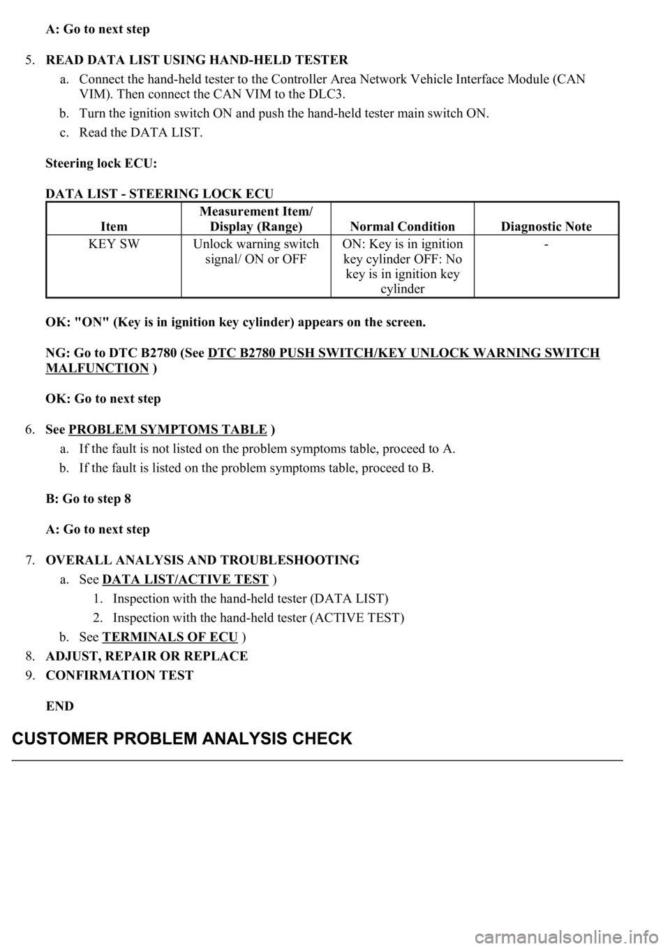
Steering lock ECU:
DATA LIST - STEERING LOCK ECU
OK: "ON" (Key is in ignition key cylinder) appears on the screen.
NG: Go to DTC B2780 (See DTC B2780 PUSH SWITCH/KEY UNLOCK WARNING SWITCH
MALFUNCTION )
OK: Go to next step
6.See PROBLEM SYMPTOMS TABLE
)
a. If the fault is not listed on the problem symptoms table, proceed to A.
b. If the fault is listed on the problem symptoms table, proceed to B.
B: Go to step 8
A: Go to next step
7.OVERALL ANALYSIS AND TROUBLESHOOTING
a. See DATA LIST/ACTIVE TEST
)
1. Inspection with the hand-held tester (DATA LIST)
2. Inspection with the hand-held tester (ACTIVE TEST)
b. See TERMINALS OF ECU
)
8.ADJUST, REPAIR OR REPLACE
9.CONFIRMATION TEST
END
Item
Measurement Item/
Display (Range)
Normal ConditionDiagnostic Note
KEY SWUnlock warning switch
signal/ ON or OFFON: Key is in ignition
key cylinder OFF: No
key is in ignition key
cylinder-
Page 3195 of 4500
Fig. 24: Checking DLC3
Courtesy of TOYOTA MOTOR SALES, U.S.A., INC.
DLC3
If the result is not as specified, the DLC3 may have a malfunction. Repair or replace the harness and
connector.
HINT:
Connect the cable of the hand-held tester (with CAN VIM) to the DLC3, turn the ignition switch ON and
attempt to use the hand-held tester. If the screen displays the message UNABLE TO CONNECT TO
VEHICLE, there is a problem either with the vehicle or with the tester.
Symbols (Terminals
No.)
Terminal DescriptionConditionSpecified Condition
SIL (7) - SG (5)Bus "+" lineDuring transmissionPulse generation
CG (4) - Body groundChassis groundAlwaysBelow 1 ohms
SG (5) - Body groundSignal groundAlwaysBelow 1 ohms
BAT (16) - Body groundBattery positiveAlways11 to 14 V