Page 4445 of 4500

HINT:
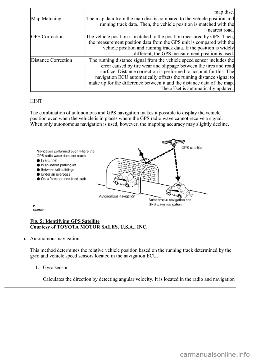
The combination of autonomous and GPS navigation makes it possible to display the vehicle
position even when the vehicle is in places where the GPS radio wave cannot receive a signal.
<003a004b00480051000300520051004f005c000300440058005700520051005200500052005800560003005100440059004c004a00440057004c005200510003004c005600030058005600480047000f0003004b0052005a0048005900480055000f000300
57004b004800030050004400530053004c0051004a00030044[ccuracy may slightly decline.
Fig. 5: Identifying GPS Satellite
Courtesy of TOYOTA MOTOR SALES, U.S.A., INC.
b. Autonomous navigation
This method determines the relative vehicle position based on the running track determined by the
gyro and vehicle speed sensors located in the navigation ECU.
1. Gyro sensor
Calculates the direction b
y detecting angular velocity. It is located in the radio and navigation
map disc.
Map MatchingThe map data from the map disc is compared to the vehicle position and
running track data. Then, the vehicle position is matched with the
nearest road.
GPS CorrectionThe vehicle position is matched to the position measured by GPS. Then,
the measurement position data from the GPS unit is compared with the
vehicle position and running track data. If the position is widely
different, the GPS measurement position is used.
Distance CorrectionThe running distance signal from the vehicle speed sensor includes the
error caused by tire wear and slippage between the tires and road
surface. Distance correction is performed to account for this. The
navigation ECU automatically offsets the running distance signal to
make up for the difference between it and the distance data of the map.
The offset is automatically updated.
Page 4447 of 4500

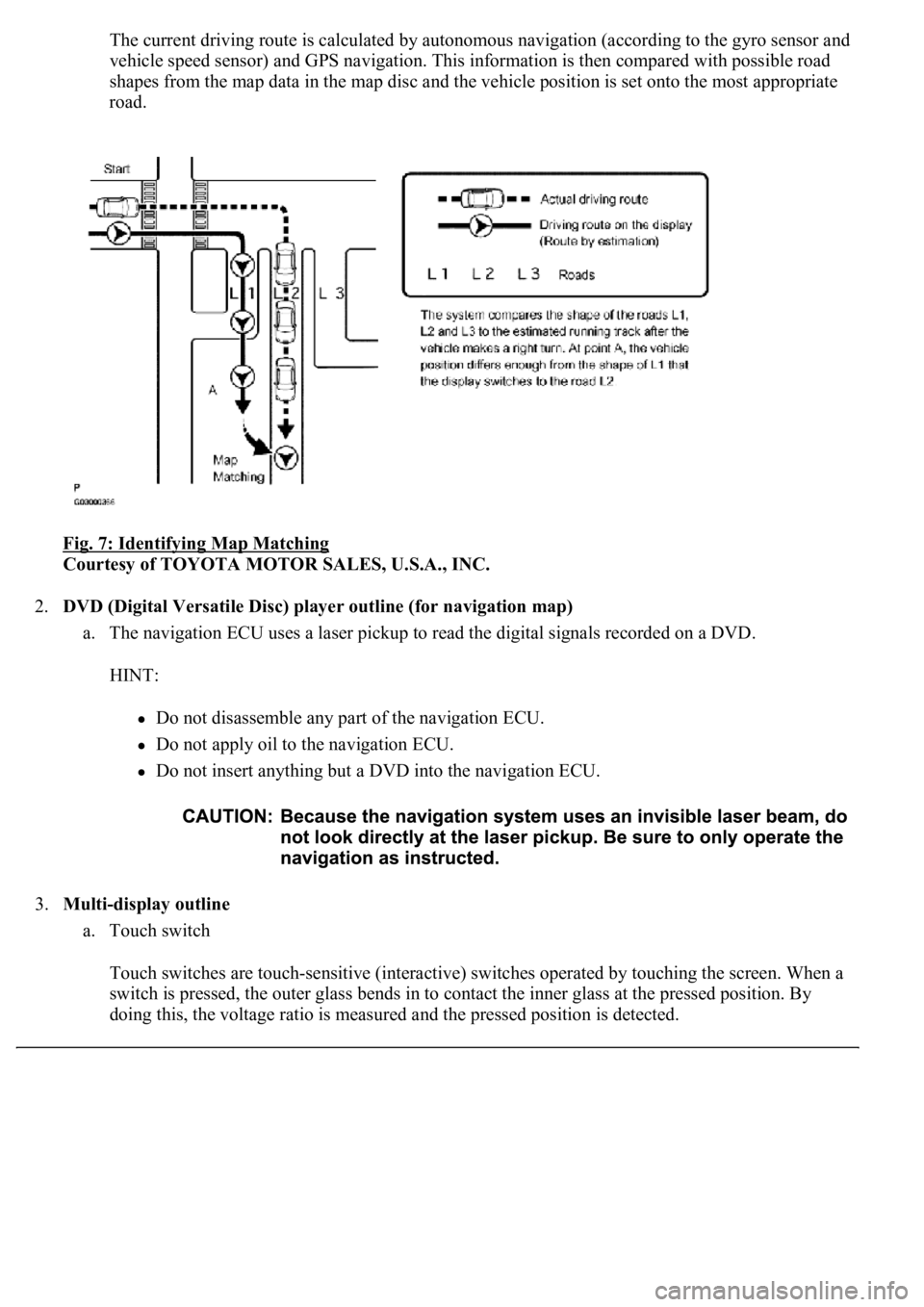
The current driving route is calculated by autonomous navigation (according to the gyro sensor and
vehicle speed sensor) and GPS navigation. This information is then compared with possible road
shapes from the map data in the map disc and the vehicle position is set onto the most appropriate
road.
Fig. 7: Identifying Map Matching
Courtesy of TOYOTA MOTOR SALES, U.S.A., INC.
2.DVD (Digital Versatile Disc) player outline (for navigation map)
a. The navigation ECU uses a laser pickup to read the digital signals recorded on a DVD.
HINT:
Do not disassemble any part of the navigation ECU.
Do not apply oil to the navigation ECU.
Do not insert anything but a DVD into the navigation ECU.
3.Multi-display outline
a. Touch switch
Touch switches are touch-sensitive (interactive) switches operated by touching the screen. When a
switch is pressed, the outer glass bends in to contact the inner glass at the pressed position. By
doing this, the voltage ratio is measured and the pressed position is detected.
Page 4448 of 4500
Fig. 8: Identifying Multi-Display Outline
Courtesy of TOYOTA MOTOR SALES, U.S.A., INC.
4.AVC-LAN Description
a. What is AVC-LAN?
AVC-LAN, an abbreviation for "Audio Visual Communication Local Area Network", is a united
standard developed by the manufacturers in affiliation with Toyota Motor Corporation. This
standard pertains to audio and visual signals as well as switch and communication signals.
Fig. 9: Identifying Avc
-Lan System
Courtesy of TOYOTA MOTOR SALES, U.S.A., INC.
b. Purpose:
Recently, car audio systems have rapidly developed and the functions vastly changed. The
conventional car audio system is being integrated with multi-media interfaces similar to those in
navigation systems. At the same time, customers are demanding higher quality from their audio
s
ystems. This is merely an overview of the standardization background. The specific purposes are
Page 4449 of 4500

as follows.
1. To solve sound problems, etc. caused by using components of different manufacturers
through signal standardization.
2. To allow each manufacturer to concentrate on developing products they do best. From this,
reasonably priced products can be produced.
HINT:
If a +B or GND short is detected in the AVC-LAN circuit, communication is interrupted and
the audio system will stop functioning.
If an audio system is equipped with a navigation system, the multi-display unit acts as the
master unit.
If the navigation system is not equipped, the audio head unit acts as the master unit instead. I
f
the radio and navigation assy is equipped, it is the master unit.
The radio receiver assy provides resistance to make communication possible.
The car audio system with an AVC-LAN circuit has a diagnostic function.
Each component has a specified number (3-digit) called a physical address. Each function
has a number (2-digit) called a logical address.
5.Communication system outline
a. Components of the navigation system communicate with each other via the AVC-LAN.
b. Radio receiver assy has enough resistance (60 to 80 ohms) necessary for transmitting the
communication. This is essential for communication.
c. If a short circuit or open circuit occurs in the AVC-LAN circuit, communication is interrupted and
the navigation system will stop functioning.
6.Diagnostic function outline
a. The audio system has a diagnostic function (the result is indicated on the master unit).
b. A 3-digit hexadecimal component code (physical address) is allocated to each component on the
AVC-LAN. Using this code, the component in the diagnostic function can be displayed.
7.Bluetooth outline
a. BLUETOOTH is a new wireless connection technology that uses the 2.4 GHz frequency band. This
makes it possible to connect a cellular phone (BLUETOOTH capable phone*1) to the multi-display
(BLUETOOTH system is built in), and use a hands-free function with the cellular phone in a
pocket or bag. As a result, it is not necessary to use a connector for the cellular phone.
*1: Some versions of BLUETOOTH capable cellular phone may not function.
HINT:
The communication performance of BLUETOOTH may vary depending on obstructions or radio
wave conditions between communication devices, electromagnetic radiation, communication
device sensitivit
y, or antenna capacity.
Page 4450 of 4500
Fig. 10: Identifying Bluetooth Capable Cellular
Courtesy of TOYOTA MOTOR SALES, U.S.A., INC.
1.Vehicle brought into a workshop
2.Diagnostic questioning and symptom confirmation (see CUSTOMER PROBLEM ANALYSIS
CHECK )
Ask the customer about symptoms and confirm malfunctions. Fill out the Customer Problem Analysis
check sheet.
The screen displays nothing (go to step 6, proceed to "BLACK SCREEN (NO IMAGE APPEARS
ON NAVIGATION/AUDIO SCREEN)")
Other symptoms (go to step 3)
3.Confirm the system normal condition (see SYSTEM NORMAL CONDITION CHECK
)
Applicable (This is not a malfunction.)
Not applicable (go to step 4)
4.Check the diagnostic trouble codes (see DIAGNOSTIC TROUBLE CODE CHART
)
HINT:
If the system cannot enter the diagnosis mode, inspect each AVC-LAN communication signal and
Page 4451 of 4500

repair or replace problem parts (see AVC-LAN CIRCUIT (NAVIGATION ECU -STEREO
COMPONENT TUNER) - AVC-LAN CIRCUIT (NAVIGATION ECU - TELEVISION
CAMERA ECU) ).
Even if the malfunction symptom is not confirmed, check the diagnostic trouble codes. This is
because the system stores past diagnostic trouble codes.
Refer to the detailed description on the diagnostic screen, as necessary (see DIAGNOSIS
DISPLAY DETAILED DESCRIPTION ).
Check and clear the past diagnostic trouble code. Check the diagnostic trouble code and inspect the
area the code indicates.
A code is output (go to step 5)
A code is not output (go to step 6)
5.(see DIAGNOSTIC TROUBLE CODE CHART
)
Find the output code on the diagnostic trouble code chart.
Output the diagnostic trouble code (go to step 8)
6.(see PROBLEM SYMPTOMS TABLE
)
Find the applicable symptom code in the problem symptoms table.
HINT:
If the symptom does not recur and no code is output, perform the symptom reproduction method (see
HOW TO PROCEED WITH TROUBLESHOOTING
).
There is an applicable symptom code in the table (go to step 8)
There is no applicable symptom code in the table (go to step 7)
7.Check the ECU terminal arrangement based on the malfunction symptom (see TERMINALS OF
ECU )
8.Check the circuit
Adjust, repair or replace as necessary.
9.Recheck the DIAGNOSTIC TROUBLE CODE CHART
HINT:
After deleting the DTC, recheck the diagnostic trouble code.
10.Perform confirmation test
Page 4453 of 4500
HINT:
<0037004b004c00560003005000520047004800030046004b00480046004e005600030057004b0048000300460052004f0052005500030047004c00560053004f0044005c00030052005100030057004b0048000300500058004f0057004c00100047004c00
560053004f0044005c001100030003[
Illustrations may differ from the actual vehicle depending on the device settings and options. Therefore,
some detailed areas may not be shown exactly the same as on the actual vehicle.
1.Enter diagnostic mode (see DIAGNOSTIC START
-UP/FINISH ).
Fig. 12: Display Diagnostic Menu
Courtesy of TOYOTA MOTOR SALES, U.S.A., INC.
2.Select "Display Check" from the "Diagnosis MENU" screen.
Page 4454 of 4500
Fig. 13: Display Checking Menu
Courtesy of TOYOTA MOTOR SALES, U.S.A., INC.
3.Select "Color Bar Check" from the "Display Check" screen.