Page 4368 of 4500
c. Disconnect the connectors.
32.REMOVE INSTRUMENT CLUSTER FINISH PANEL SUB-ASSY CENTER (W/O LEXUS
NAVIGATION SYSTEM)
a. Remove the 2 bolts.
HINt:
Be careful not to drop the bolts when removing them from the display.
b. Using a moulding remover, disengage the 4 clips and remove the instrument cluster finish panel
sub-assy center.
Fig. 20: Removing Instrument Cluster Finish Panel Sub
-Assy Center (W/O Lexus Navigation
System)
Courtesy of TOYOTA MOTOR SALES, U.S.A., INC.
HINt:
Remove the multi-display together with instrument cluster finish panel sub-assy center.
Use a screwdriver if a moulding remover is not available.
Page 4392 of 4500
Fig. 43: Removing Combination Meter Cover No.1
Courtesy of TOYOTA MOTOR SALES, U.S.A., INC.
8.REMOVE METER DISPLAY PANEL
a. Remove the 8 screws.
b. Remove the meter display panel.
Page 4393 of 4500
Fig. 44: Removing Meter Display Panel
Courtesy of TOYOTA MOTOR SALES, U.S.A., INC.
9.REMOVE COMBINATION METER ECU
a. Remove the 4 screws.
b. Disconnect the connectors.
c. Using a screwdriver, disengage the claw and remove the combination meter ECU.
HINT:
Tape up the screwdriver tip before use.
Page 4419 of 4500
Fig. 5: Customer Problem Analysis Check Sheet
Courtesy of TOYOTA MOTOR SALES, U.S.A., INC.
HINT:
The following items can be customized.
Meter ECU:
CUSTOMIZE PARAMETERS
Display (Item)DefaultContentsSetting
KEY REMND
VOLUMLARGEFunction that changes key reminder
buzzer's volumeLARGE/MEDIUM/SMALL
Page 4425 of 4500

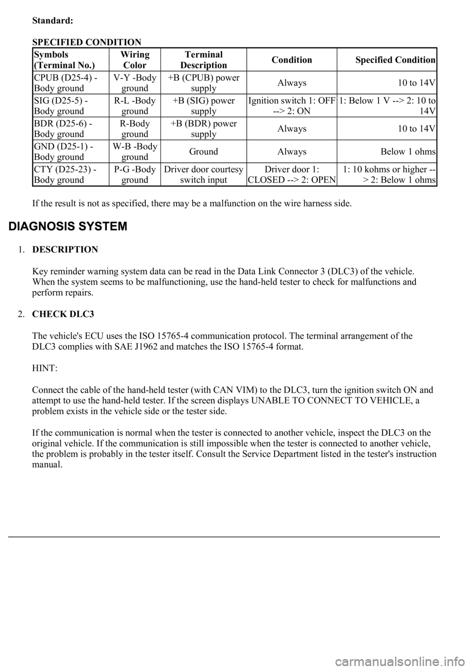
Standard:
SPECIFIED CONDITION
If the result is not as specified, there may be a malfunction on the wire harness side.
1.DESCRIPTION
Key reminder warning system data can be read in the Data Link Connector 3 (DLC3) of the vehicle.
When the system seems to be malfunctioning, use the hand-held tester to check for malfunctions and
perform repairs.
2.CHECK DLC3
The vehicle's ECU uses the ISO 15765-4 communication protocol. The terminal arrangement of the
DLC3 complies with SAE J1962 and matches the ISO 15765-4 format.
HINT:
Connect the cable of the hand-held tester (with CAN VIM) to the DLC3, turn the ignition switch ON and
attempt to use the hand-held tester. If the screen displays UNABLE TO CONNECT TO VEHICLE, a
problem exists in the vehicle side or the tester side.
If the communication is normal when the tester is connected to another vehicle, inspect the DLC3 on the
original vehicle. If the communication is still impossible when the tester is connected to another vehicle,
the problem is probably in the tester itself. Consult the Service Department listed in the tester's instruction
manual.
Symbols
(Terminal No.)Wiring
ColorTerminal
DescriptionConditionSpecified Condition
CPUB (D25-4) -
Body groundV-Y -Body
ground+B (CPUB) power
supplyAlways10 to 14V
SIG (D25-5) -
Body groundR-L -Body
ground+B (SIG) power
supplyIgnition switch 1: OFF
--> 2: ON1: Below 1 V --> 2: 10 to
14V
BDR (D25-6) -
Body groundR-Body
ground+B (BDR) power
supplyAlways10 to 14V
GND (D25-1) -
Body groundW-B -Body
groundGroundAlwaysBelow 1 ohms
CTY (D25-23) -
Body groundP-G -Body
groundDriver door courtesy
switch inputDriver door 1:
CLOSED --> 2: OPEN1: 10 kohms or higher --
> 2: Below 1 ohms
Page 4428 of 4500
to save time. The DATA LIST can be displayed during the ACTIVE TEST.
a. Connect the hand-held tester (with CAN VIM) to the DLC3.
b. Turn the ignition switch ON.
c. Perform the ACTIVE TEST according to the display on the tester.
Meter ECU:
ACTIVE TEST - METER ECU
CIRCUIT DESCRIPTION
This circuit supplies power to operate the driver door ECU.
WIRING DIAGRAM
ItemTest DetailsDiagnostic Note
KEY REMINDER BUZZERCombination meter warning buzzer OFF/ON-
Page 4443 of 4500
Courtesy of TOYOTA MOTOR SALES, U.S.A., INC.
1.Navigation system outline
a. Vehicle position tracking methods
It is essential that the navigation system correctly tracks the current vehicle position and displays it
on the map. There are 2 methods to track the current vehicle position: autonomous (dead
reckoning) and GPS* (satellite) navigation. Both navigation methods are used in conjunction with
each other.
* GPS (Global Positionin
g System)
Page 4444 of 4500
Fig. 4: Identifying Navigation System Outline
Courtesy of TOYOTA MOTOR SALES, U.S.A., INC.
OPERATION DESCRIPTION CHART
OperationDescription
Vehicle Position
CalculationThe navigation ECU calculates the current vehicle position (direction
and current position) using the direction deviation signal from the gyro
sensor and the running distance signal from the vehicle speed sensor and
creates the driving route.
Map Display processingThe navigation ECU displays the vehicle track on the map by processing
the vehicle position data, vehicle running track, and map data from the