Page 3925 of 4500
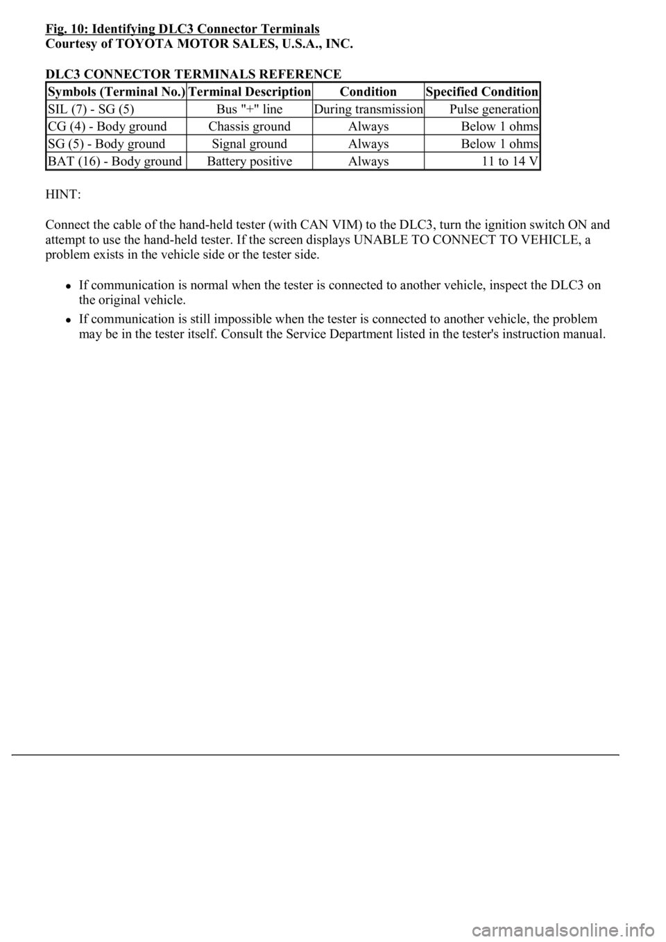
Fig. 10: Identifying DLC3 Connector Terminals
Courtesy of TOYOTA MOTOR SALES, U.S.A., INC.
DLC3 CONNECTOR TERMINALS REFERENCE
HINT:
Connect the cable of the hand-held tester (with CAN VIM) to the DLC3, turn the ignition switch ON and
attempt to use the hand-held tester. If the screen displays UNABLE TO CONNECT TO VEHICLE, a
problem exists in the vehicle side or the tester side.
If communication is normal when the tester is connected to another vehicle, inspect the DLC3 on
the original vehicle.
If communication is still impossible when the tester is connected to another vehicle, the problem
may be in the tester itself. Consult the Service Department listed in the tester's instruction manual.
Symbols (Terminal No.)Terminal DescriptionConditionSpecified Condition
SIL (7) - SG (5)Bus "+" lineDuring transmissionPulse generation
CG (4) - Body groundChassis groundAlwaysBelow 1 ohms
SG (5) - Body groundSignal groundAlwaysBelow 1 ohms
BAT (16) - Body groundBattery positiveAlways11 to 14 V
Page 3930 of 4500
time. The DATA LIST can be displayed during the ACTIVE TEST.
a. Connect the hand-held tester (with CAN VIM) to the DLC3.
b. Turn the ignition switch ON.
c. Perform the ACTIVE TEST by following the directions on the tester screen.
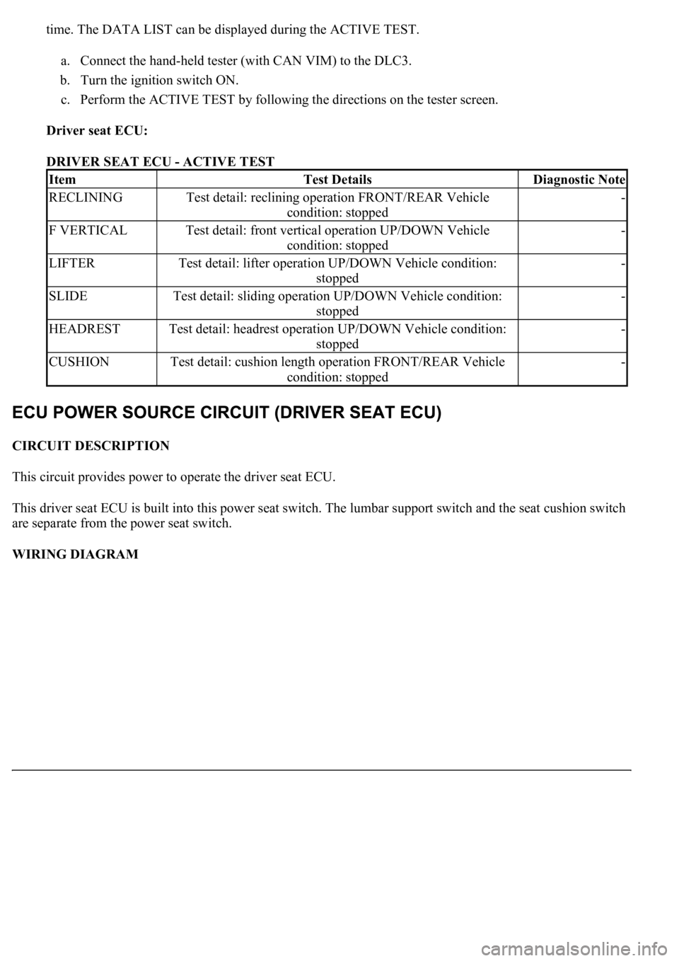
Driver seat ECU:
DRIVER SEAT ECU - ACTIVE TEST
CIRCUIT DESCRIPTION
This circuit provides power to operate the driver seat ECU.
This driver seat ECU is built into this power seat switch. The lumbar support switch and the seat cushion switch
are separate from the power seat switch.
WIRING DIAGRAM
ItemTest DetailsDiagnostic Note
RECLININGTest detail: reclining operation FRONT/REAR Vehicle
condition: stopped-
F VERTICALTest detail: front vertical operation UP/DOWN Vehicle
condition: stopped-
LIFTERTest detail: lifter operation UP/DOWN Vehicle condition:
stopped-
SLIDETest detail: sliding operation UP/DOWN Vehicle condition:
stopped-
HEADRESTTest detail: headrest operation UP/DOWN Vehicle condition:
stopped-
CUSHIONTest detail: cushion length operation FRONT/REAR Vehicle
condition: stopped-
Page 3944 of 4500
INSPECTION PROCEDURE
1.READ VALUE OF HAND-HELD TESTER
a. Connect the hand-held tester (with CAN VIM) to the DLC3.
b. Turn the ignition switch ON and press the hand-held tester main switch ON.
c. Select the items below in the DATA LIST, and read the hand-held tester's screen.
d. Watch the hand-held tester screen while adjusting the seat with the power seat control switches.
Check that the position sensor value changes.
e. Watch the hand-held tester screen while adjusting the seat with the power seat control switches.
Check that the motor status changes from STANDBY to MOVING.
HINT:
When the seat is at an extreme position (for example, seatback position fully forward or sliding position
fully rearward) and the power seat control switch is held down, the motor status should read LOCK.
When the switch is released, the motor status should change to STANDBY.
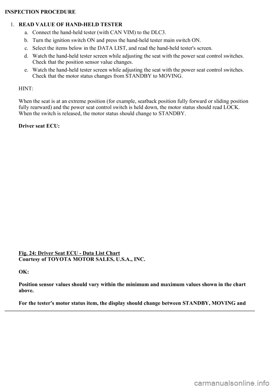
Driver seat ECU:
Fig. 24: Driver Seat ECU
- Data List Chart
Courtesy of TOYOTA MOTOR SALES, U.S.A., INC.
OK:
Position sensor values should vary within the minimum and maximum values shown in the chart
above.
For the tester's motor status item, the display should change between STANDBY, MOVING and
Page 3961 of 4500
Driver seat ECU:
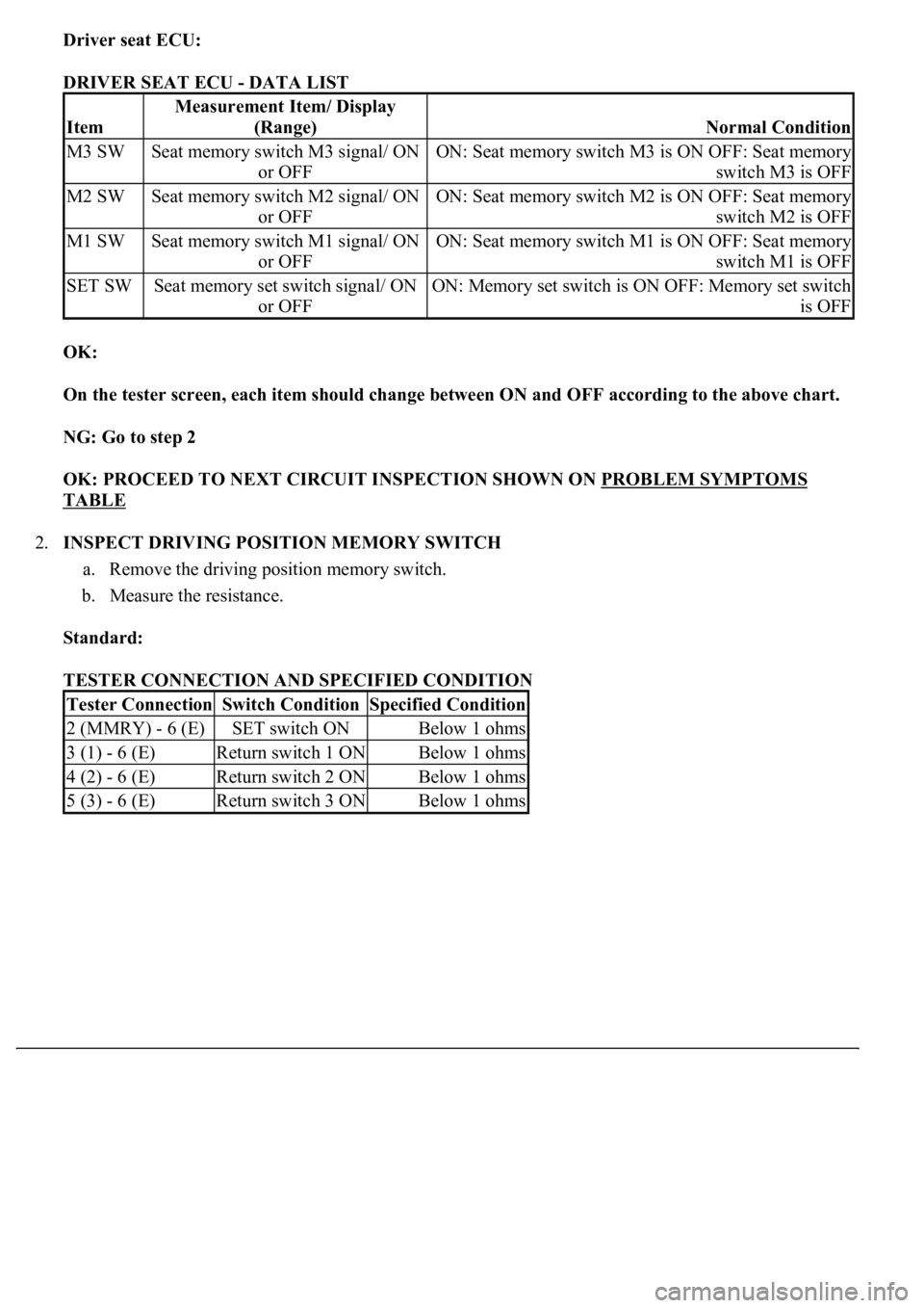
DRIVER SEAT ECU - DATA LIST
OK:
On the tester screen, each item should change between ON and OFF according to the above chart.
NG: Go to step 2
OK: PROCEED TO NEXT CIRCUIT INSPECTION SHOWN ON PROBLEM SYMPTOMS
TABLE
2.INSPECT DRIVING POSITION MEMORY SWITCH
a. Remove the driving position memory switch.
b. Measure the resistance.
Standard:
TESTER CONNECTION AND SPECIFIED CONDITION
Item
Measurement Item/ Display
(Range)
Normal Condition
M3 SWSeat memory switch M3 signal/ ON
or OFFON: Seat memory switch M3 is ON OFF: Seat memory
switch M3 is OFF
M2 SWSeat memory switch M2 signal/ ON
or OFFON: Seat memory switch M2 is ON OFF: Seat memory
switch M2 is OFF
M1 SWSeat memory switch M1 signal/ ON
or OFFON: Seat memory switch M1 is ON OFF: Seat memory
switch M1 is OFF
SET SWSeat memory set switch signal/ ON
or OFFON: Memory set switch is ON OFF: Memory set switch
is OFF
Tester ConnectionSwitch ConditionSpecified Condition
2 (MMRY) - 6 (E)SET switch ONBelow 1 ohms
3 (1) - 6 (E)Return switch 1 ONBelow 1 ohms
4 (2) - 6 (E)Return switch 2 ONBelow 1 ohms
5 (3) - 6 (E)Return switch 3 ONBelow 1 ohms
Page 4081 of 4500
Fig. 11: Identifying Terminals Of DLC3
Courtesy of TOYOTA MOTOR SALES, U.S.A., INC.
2.CHECK DLC3
The vehicle's ECU uses the ISO 15765-4 communication protocol. The terminal arrangement of the
DLC3 complies with SAE J1962 and matches the ISO 15765-4 format.
HINT:
Connect the cable of the hand-held tester (with CAN VIM) to the DLC3, turn the ignition switch ON and
attempt to use the hand-held tester. If the screen displays UNABLE TO CONNECT TO VEHICLE, a
problem exists in the vehicle side or the tester side.
If the communication is normal when the tester is connected to another vehicle, inspect the DLC3 on the
original vehicle.
If the communication is still impossible when the tester is connected to another vehicle, the problem is
probably in the tester itself. Consult the Service Department listed in the tester's instruction manual.
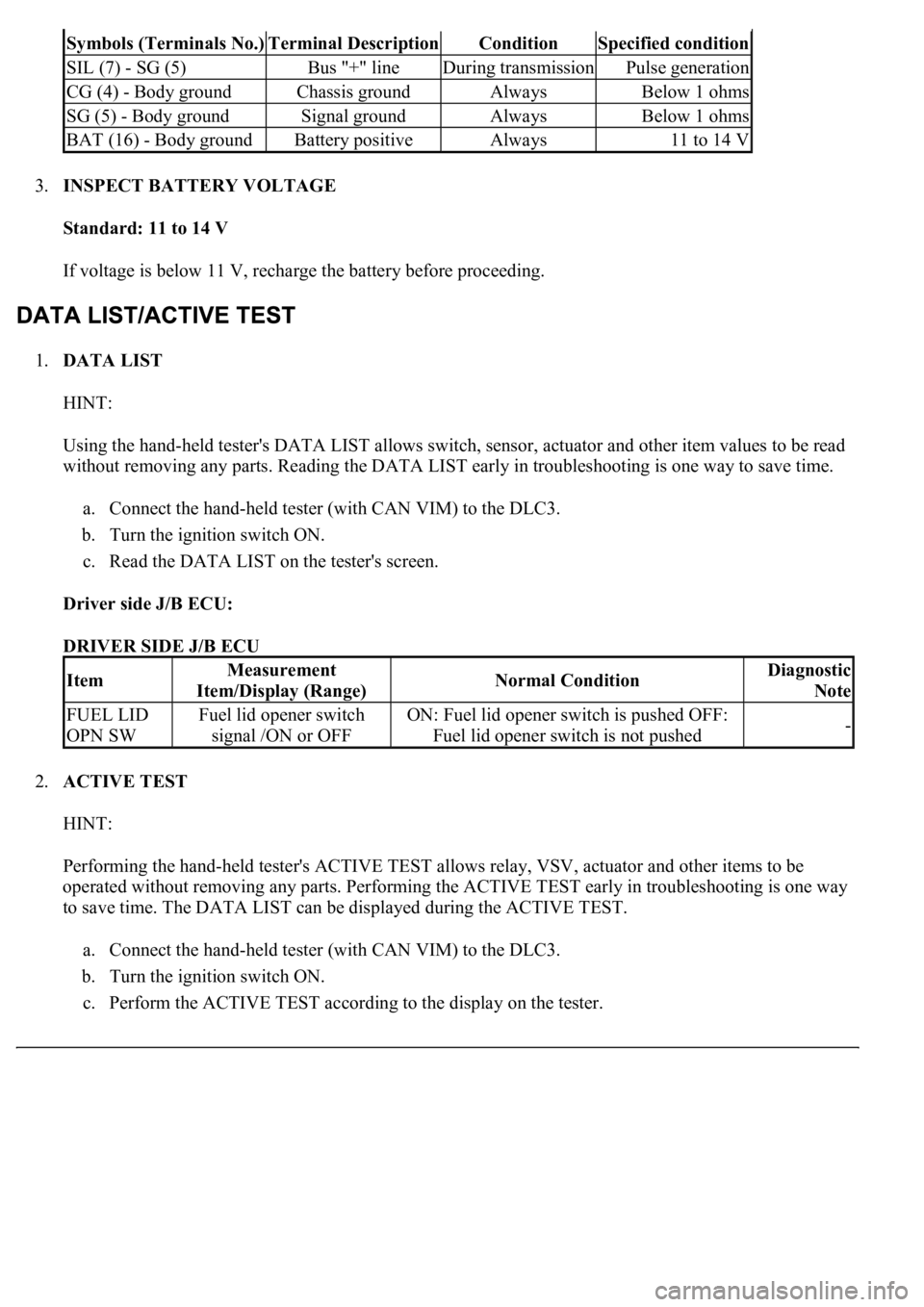
TERMINAL DESCRIPTION AND SPECIFIED CONDITION
Page 4082 of 4500
3.INSPECT BATTERY VOLTAGE
Standard: 11 to 14 V
If voltage is below 11 V, recharge the battery before proceeding.
1.DATA LIST
HINT:
Using the hand-held tester's DATA LIST allows switch, sensor, actuator and other item values to be read
without removing any parts. Reading the DATA LIST early in troubleshooting is one way to save time.
a. Connect the hand-held tester (with CAN VIM) to the DLC3.
b. Turn the ignition switch ON.
c. Read the DATA LIST on the tester's screen.
Driver side J/B ECU:
DRIVER SIDE J/B ECU
2.ACTIVE TEST
HINT:
Performing the hand-held tester's ACTIVE TEST allows relay, VSV, actuator and other items to be
operated without removing any parts. Performing the ACTIVE TEST early in troubleshooting is one way
to save time. The DATA LIST can be displayed during the ACTIVE TEST.
a. Connect the hand-held tester (with CAN VIM) to the DLC3.
b. Turn the ignition switch ON.
c. Perform the ACTIVE TEST accordin
g to the display on the tester.
Symbols (Terminals No.)Terminal DescriptionConditionSpecified condition
SIL (7) - SG (5)Bus "+" lineDuring transmissionPulse generation
CG (4) - Body groundChassis groundAlwaysBelow 1 ohms
SG (5) - Body groundSignal groundAlwaysBelow 1 ohms
BAT (16) - Body groundBattery positiveAlways11 to 14 V
ItemMeasurement
Item/Display (Range)Normal ConditionDiagnostic
Note
FUEL LID
OPN SWFuel lid opener switch
signal /ON or OFFON: Fuel lid opener switch is pushed OFF:
Fuel lid opener switch is not pushed-
Page 4088 of 4500
DRIVER SIDE J/B ECU
OK: "ON" (fuel lid opener switch is pulled) appears on the screen.
NG: Go to step 2
OK: PROCEED TO NEXT CIRCUIT INSPECTION SHOWN ON PROBLEM SYMPTOMS
TABLE
2.INSPECT LUGGAGE DOOR OPENING SWITCH ASSY (FUEL LID OPENER SWITCH)
a. Measure the resistance of the switch.
Standard:
TESTER CONNECTION AND SPECIFIED CONDITION
NG: REPLACE LUGGAGE DOOR OPENING SWITCH ASSY
ItemMeasurement
Item/Display (Range)Normal ConditionDiagnostic
Note
FUEL LID
OPN SWFuel lid opener switch
signal /ON or OFFON: Fuel lid opener switch is pulled OFF:
Fuel lid opener switch is not pulled-
Tester ConnectionSwitch ConditionSpecified Condition
A-1 - A-2OFF (not pulled)10 kohms or higher
A-1 - A-2ON (pulled)Below 1 ohms
Page 4367 of 4500
Fig. 19: Removing Instrument Cluster Finish Panel Sub-Assy Center (W/ Lexus Navigation
System)
Courtesy of TOYOTA MOTOR SALES, U.S.A., INC.
31.REMOVE INSTRUMENT CLUSTER FINISH PANEL SUB-ASSY CENTER (W/ LEXUS
NAVIGATION SYSTEM)
a. Remove the 4 bolts.
HINt:
Be careful not to drop the bolts when removing them from the display.
b. Using a moulding remover, disengage the 4 clips and remove the instrument cluster finish panel
sub-assy center.
HINt:
Remove the multi-display together with instrument cluster finish panel sub-assy center.
Use a screwdriver if a moulding remover is not available.
tape up the screwdriver tip before use.