Page 2713 of 4500
Fig. 35: DTC Freeze Frame Specification
Courtesy of TOYOTA MOTOR SALES, U.S.A., INC.
DLC3 (Data Link Connector 3)
The vehicle's ECM uses the ISO 15765-4 for communication protocol. The terminal arrangement of the DLC3
complies with SAE J1962 and matches the ISO 15765-4 format.
HINT:
Connect the cable of the hand-held tester to the DLC3, turn the ignition switch ON and attempt to use the hand-
held tester. If the screen displays UNABLE TO CONNECT TO VEHICLE, a problem exists in the vehicle side
or the tester side.
If the communication is normal when the tool is connected to another vehicle, inspect the DLC3 on the original
vehicle.
If the communication is still impossible when the tool is connected to another vehicle, the problem is probably
in the tool itself. Consult the Service Department listed in the tool's instruction manual.
Page 2715 of 4500

CHECK BATTERY VOLTAGE
Battery voltage: 11 to 14 V
If voltage is below 11 V, replace the battery before proceeding.
CHECK MIL
a. Check that the MIL illuminates when turning the ignition switch ON.
If the MIL does not illuminate, there is a problem in the MIL circuit (refer to MIL CIRCUIT
)
b. When the engine is started, the MIL should turn off.
ALL READINESS
For this vehicle, using the hand-held tester allows readiness codes corresponding to all DTCs to be read. When
diagnosis (normal or malfunctioning) has been complete, readiness codes are set. Enter the following menus:
ENHANCED OBD II/ MONITOR STATUS on the hand-held tester.
DTC CHECK/CLEAR
1.CHECK DTC
DTCs which are stored in the ECM can be displayed with the hand-held tester or generic OBD II scan-
tool.
These scan tools can display pending DTCs and current DTCs. Some DTC aren't stored if the ECM
doesn't detect a malfunction during consecutive driving. However, the detected malfunction during once
driving is stored as pending DTC.
1. Connect the hand-held tester to the Controller Area Network Vehicle Interface Module (CAN
VIM). Then connect the CAN VIM to the Data Link Connector 3 (DLC3).
2. Turn the ignition switch ON.
3. Enter the following menus: DIAGNOSIS/ ENHANCED OBD II/ DTC INFO/ CURRENT CODES
(or PENDING CODE).
4. Confirm the DTCs and freeze frame data and then write them down.
5. See DIAGNOSTIC TROUBLE CODE CHART
to confirm the details of the DTCs.
CAN bus linehigher
Page 2722 of 4500
b. Fail-safe operation for mechanically malfunction:
HINT:
Fail-safe operation in the event of a mechanical system malfunction.
Fail safe function:
The ECM controls the gear position as shown in the table below when malfunctions occur.
Fig. 43: Identifying Mechanical Malfunction Chart
Courtesy of TOYOTA MOTOR SALES, U.S.A., INC.
DATA LIST/ACTIVE TEST
1.DATA LIST
HINT:
According to the DATA LIST displayed by the hand-held tester, you can read the value of the switch,
sensor, actuator and so on without parts removal. Reading the DATA LIST as the first step of
troubleshooting is one method to shorten labor time.
Page 2723 of 4500
a. Warm up the engine.
b. Turn the ignition switch off.
c. Connect the hand-held tester together with the CAN VIM (controller area network vehicle interface
module) to the DLC3.
d. Turn the ignition switch to the ON position.
e. Push the "ON" button of the hand-held tester.
f. Select the item "DIAGNOSIS/ENHANCED OBD II/DATA LIST".
g. According to the display on tester, read the "DATA LIST".
Fig. 44: Identifying Data List Reference (1 Of 2)
Courtesy of TOYOTA MOTOR SALES, U.S.A., INC.
Page 2724 of 4500
Fig. 45: Identifying Data List Reference (2 Of 2)
Courtesy of TOYOTA MOTOR SALES, U.S.A., INC.
2.ACTIVE TEST
HINT:
Performing the ACTIVE TEST using the hand-held tester allows the relay, VSV, actuator and so on to
operate without parts removal. Performing the ACTIVE TEST as the first step of troubleshooting is one
method to shorten labor time.
It is possible to display the DATA LIST during the ACTIVE TEST.
a. Warm up the engine.
b. Turn the ignition switch off.
c. Connect the hand-held tester together with the CAN VIM (controller area network vehicle interface
module) to the DLC3.
d. Turn the ignition switch to the ON position.
e. Push the "ON" button of the hand-held tester.
f. Select the item "DIAGNOSIS/ENHANCED OBD II/ACTIVE TEST".
g. According to the display on tester, perform the "ACTIVE TEST".
Page 2725 of 4500
Fig. 46: Test Item Reference Chart
Courtesy of TOYOTA MOTOR SALES, U.S.A., INC.
HINT:
The pressure values in ACTIVE TEST and HYDRAULIC TEST are different from each other.
DIAGNOSTIC TROUBLE CODE CHART
If a DTC is displayed during the DTC check, check the parts listed in the table below.
DTC LIST
DTCDescription
DTC P0705, P0850TRANSMISSION RANGE SENSOR CIRCUIT
MALFUNCTION (PRNDL INPUT),
PARK/NEUTRAL SWITCH INPUT CIRCUIT
DTC P0710, P0712, P0713TRANSMISSION FLUID TEMPERATURE
SENSOR "A" CIRCUIT LOW/HIGH INPUT
DTC P0711TRANSMISSION FLUID TEMPERATURE
SENSOR "A" PERFORMANCE
DTC P0717TURBINE SPEED SENSOR CIRCUIT NO SIGNAL
DTC P0724BRAKE SWITCH "B" CIRCUIT HIGH
DTC P0729GEAR 6 INCORRECT RATIO
DTC P0748PRESSURE CONTROL SOLENOID "A"
ELECTRICAL (SHIFT SOLENOID VALVE SL1)
Page 2734 of 4500
According to the DATA LIST displayed by the hand-held tester, you can read the value of the switch, sensor,
actuator and so on without parts removal. Reading the DATA LIST as the first step of troubleshooting is one
method to shorten labor time.
a. Turn the ignition switch off.
b. Connect the hand-held tester together with the CAN VIM (controller area network vehicle interface
module) to the DLC3.
c. Turn the ignition switch to the ON position.
d. Push the "ON" button of the OBD II scan tool or the hand-held tester.
e. Select the item "DIAGNOSIS/ENHANCED OBD II/DATA LIST".
f. According to the display on tester, read the "DATA LIST".
Fig. 51: Test Item Reference Chart
Courtesy of TOYOTA MOTOR SALES, U.S.A., INC.
1.INSPECT PARK/NEUTRAL POSITION SWITCH ASSY
a. Disconnect the park/neutral position switch connector.
b. Measure resistance according to the value(s) in the table below when the shift lever is moved to
each position.
Page 2742 of 4500

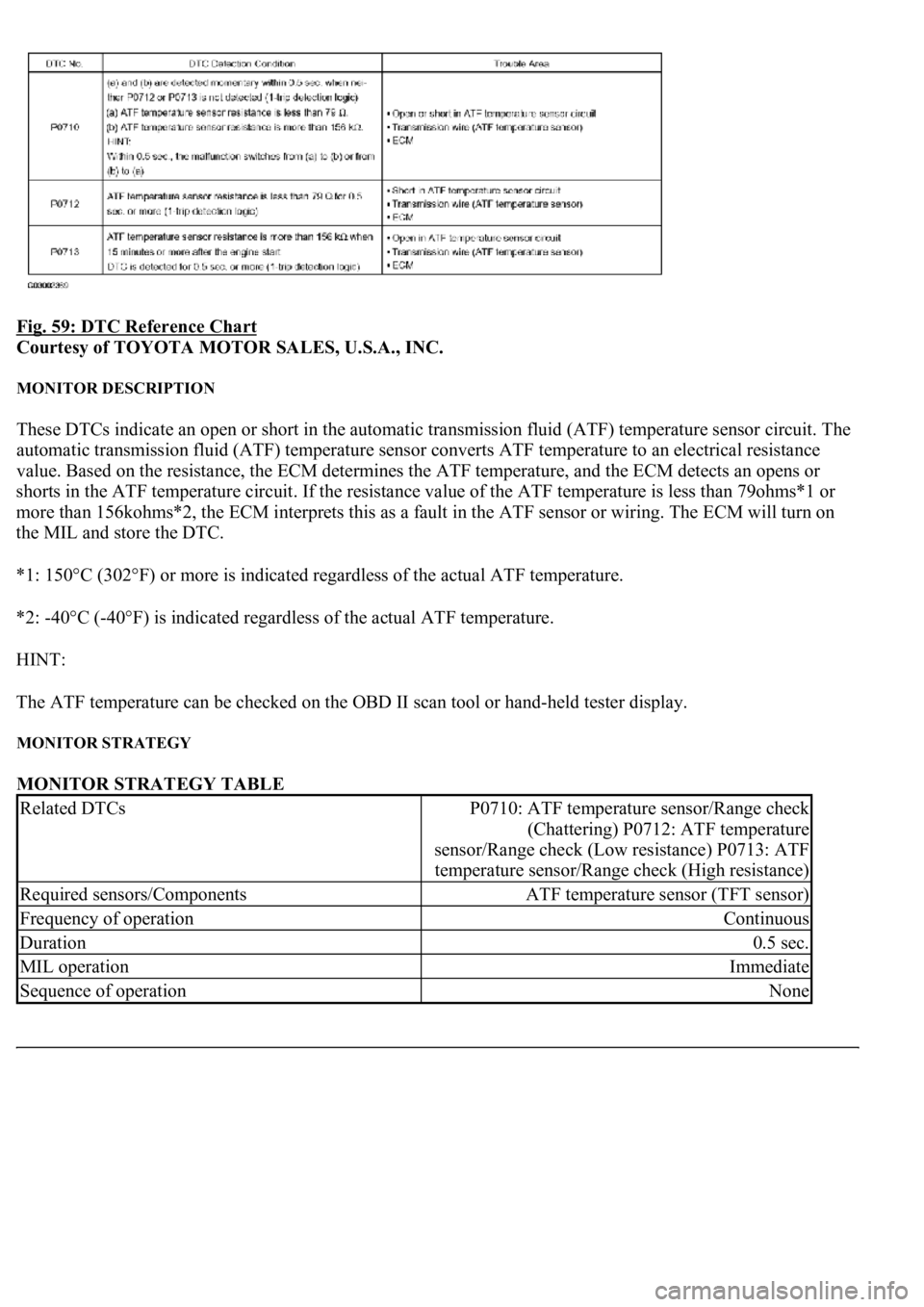
Fig. 59: DTC Reference Chart
Courtesy of TOYOTA MOTOR SALES, U.S.A., INC.
MONITOR DESCRIPTION
These DTCs indicate an open or short in the automatic transmission fluid (ATF) temperature sensor circuit. The
automatic transmission fluid (ATF) temperature sensor converts ATF temperature to an electrical resistance
value. Based on the resistance, the ECM determines the ATF temperature, and the ECM detects an opens or
shorts in the ATF temperature circuit. If the resistance value of the ATF temperature is less than 79ohms*1 or
more than 156kohms*2, the ECM interprets this as a fault in the ATF sensor or wiring. The ECM will turn on
the MIL and store the DTC.
*1: 150°C (302°F) or more is indicated regardless of the actual ATF temperature.
*2: -40°C (-40°F) is indicated regardless of the actual ATF temperature.
HINT:
The ATF temperature can be checked on the OBD II scan tool or hand-held tester display.
MONITOR STRATEGY
MONITOR STRATEGY TABLE
Related DTCsP0710: ATF temperature sensor/Range check
(Chattering) P0712: ATF temperature
sensor/Range check (Low resistance) P0713: ATF
temperature sensor/Range check (High resistance)
Required sensors/ComponentsATF temperature sensor (TFT sensor)
Frequency of operationContinuous
Duration0.5 sec.
MIL operationImmediate
Sequence of operationNone