Page 2031 of 4500
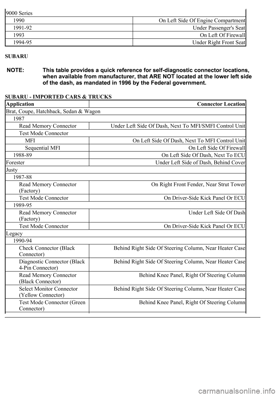
SUBARU
SUBARU - IMPORTED CARS & TRUCKS
9000 Series
1990On Left Side Of Engine Compartment
1991-92Under Passenger's Seat
1993On Left Of Firewall
1994-95Under Right Front Seat
ApplicationConnector Location
Brat, Coupe, Hatchback, Sedan & Wagon
1987
Read Memory ConnectorUnder Left Side Of Dash, Next To MFI/SMFI Control Unit
Test Mode Connector
MFIOn Left Side Of Dash, Next To MFI Control Unit
Sequential MFIOn Left Side Of Firewall
1988-89On Left Side Of Dash, Next To ECU
ForesterUnder Left Side of Dash, Behind Cover
Justy
1987-88
Read Memory Connector
(Factory)On Right Front Fender, Near Strut Tower
Test Mode ConnectorOn Driver-Side Kick Panel Or ECU
1989-95
Read Memory Connector
(Factory)Under Left Side Of Dash
Test Mode ConnectorOn Driver-Side Kick Panel Or ECU
Legacy
1990-94
Check Connector (Black
Connector)Behind Right Side Of Steering Column, Near Heater Case
Diagnostic Connector (Black
4-Pin Connector)Behind Right Side Of Steering Column, Near Heater Case
Read Memory Connector
(Black Connector)Behind Knee Panel, Right Of Steering Column
Select Monitor Connector
(Yellow Connector)Behind Right Side Of Steering Column, Near Heater Case
Test Mode Connector (Green
Connector)Behind Knee Panel, Right Of Steering Column
Page 2032 of 4500
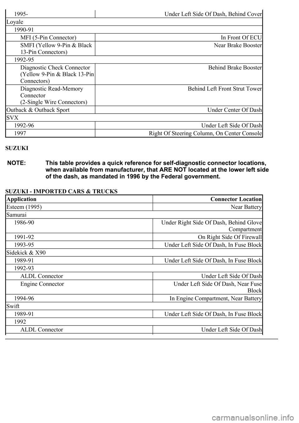
SUZUKI
SUZUKI - IMPORTED CARS & TRUCKS
1995-Under Left Side Of Dash, Behind Cover
Loyale
1990-91
MFI (5-Pin Connector)In Front Of ECU
SMFI (Yellow 9-Pin & Black
13-Pin Connectors)Near Brake Booster
1992-95
Diagnostic Check Connector
(Yellow 9-Pin & Black 13-Pin
Connectors)Behind Brake Booster
Diagnostic Read-Memory
Connector
(2-Single Wire Connectors)Behind Left Front Strut Tower
Outback & Outback SportUnder Center Of Dash
SVX
1992-96Under Left Side Of Dash
1997Right Of Steering Column, On Center Console
ApplicationConnector Location
Esteem (1995)Near Battery
Samurai
1986-90Under Right Side Of Dash, Behind Glove
Compartment
1991-92On Right Side Of Firewall
1993-95Under Left Side Of Dash, In Fuse Block
Sidekick & X90
1989-91Under Left Side Of Dash, In Fuse Block
1992-93
ALDL ConnectorUnder Left Side Of Dash
Engine ConnectorUnder Left Side Of Dash, Near Fuse
Block
1994-96In Engine Compartment, Near Battery
Swift
1989-91Under Left Side Of Dash, In Fuse Block
1992
ALDL ConnectorUnder Left Side Of Dash
Page 2033 of 4500
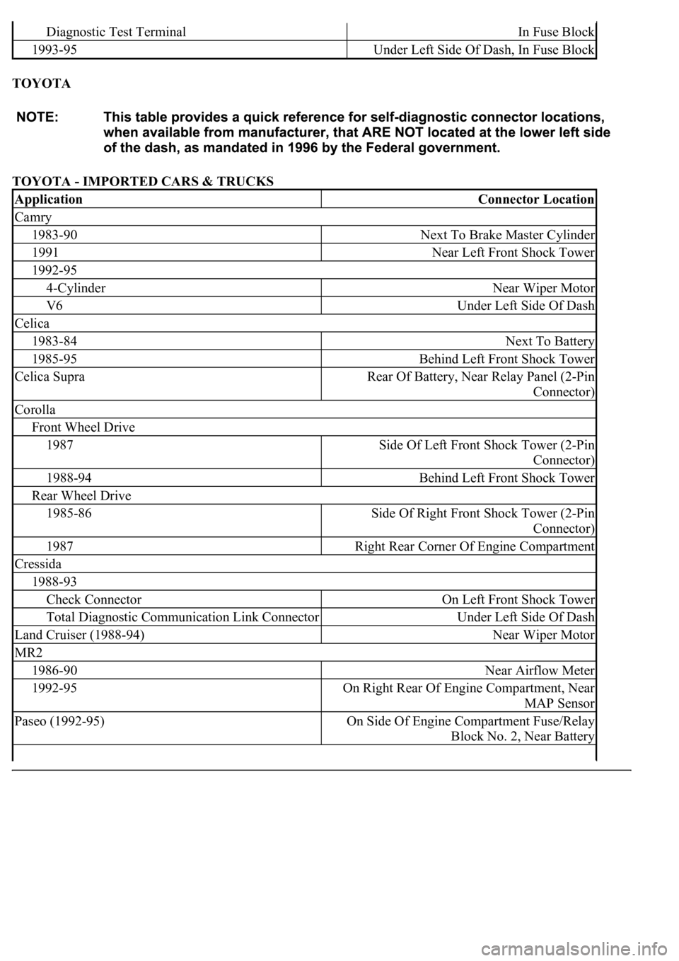
TOYOTA
TOYOTA - IMPORTED CARS & TRUCKS
Diagnostic Test TerminalIn Fuse Block
1993-95Under Left Side Of Dash, In Fuse Block
ApplicationConnector Location
Camry
1983-90Next To Brake Master Cylinder
1991Near Left Front Shock Tower
1992-95
4-CylinderNear Wiper Motor
V6Under Left Side Of Dash
Celica
1983-84Next To Battery
1985-95Behind Left Front Shock Tower
Celica SupraRear Of Battery, Near Relay Panel (2-Pin
Connector)
Corolla
Front Wheel Drive
1987Side Of Left Front Shock Tower (2-Pin
Connector)
1988-94Behind Left Front Shock Tower
Rear Wheel Drive
1985-86Side Of Right Front Shock Tower (2-Pin
Connector)
1987Right Rear Corner Of Engine Compartment
Cressida
1988-93
Check ConnectorOn Left Front Shock Tower
Total Diagnostic Communication Link ConnectorUnder Left Side Of Dash
Land Cruiser (1988-94)Near Wiper Motor
MR2
1986-90Near Airflow Meter
1992-95On Right Rear Of Engine Compartment, Near
MAP Sensor
Paseo (1992-95)On Side Of Engine Compartment Fuse/Relay
Block No. 2, Near Battery
Page 2450 of 4500
Fig. 18: Multi-Information Display Chart On Combination Meter
Courtesy of TOYOTA MOTOR SALES, U.S.A., INC.
HINT:
The indication is immediately set to "LONG" each time the engine is started.
If a normal system code is displayed during the DTC check but the problem still occurs, check the suspected
areas for each problem symptom in the order given in the table below and proceed to the relevant
troubleshooting page.
HINT:
Inspect the "Fuse" and "Relay" before confirming the suspected areas as shown in the chart below. Inspect each
suspected area for the correspondin
g symptom in numerical order.
Page 2550 of 4500
Fig. 18: Multi-Information Display Chart On Combination Meter
Courtesy of TOYOTA MOTOR SALES, U.S.A., INC.
HINT:
The indication is immediately set to "LONG" each time the engine is started.
If a normal system code is displayed during the DTC check but the problem still occurs, check the suspected
areas for each problem symptom in the order given in the table below and proceed to the relevant
troubleshooting page.
HINT:
Inspect the "Fuse" and "Relay" before confirming the suspected areas as shown in the Fig. 19
below. Inspect
each suspected area for the correspondin
g symptom in numerical order.
Page 2676 of 4500
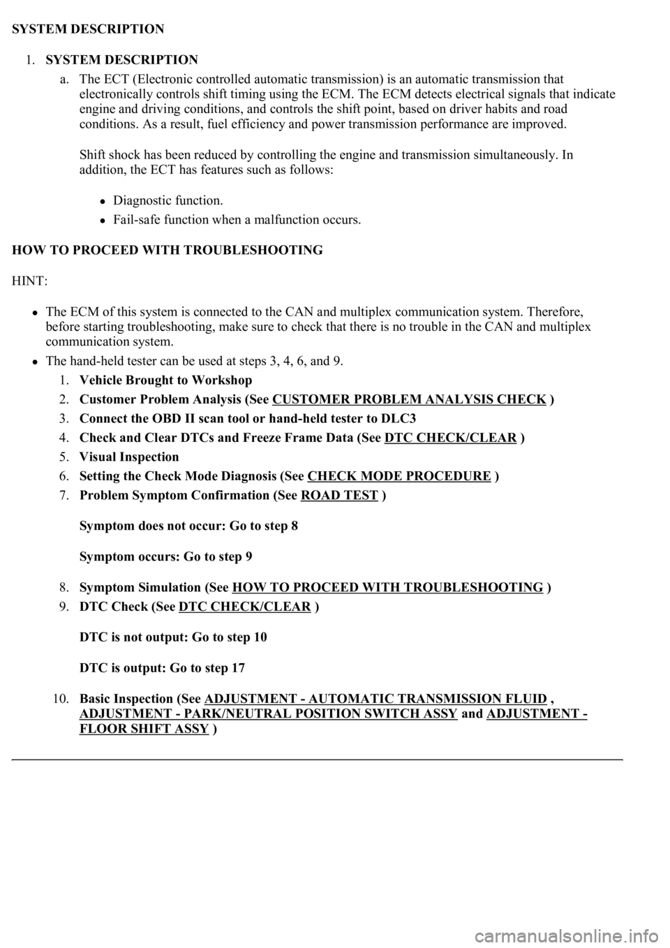
SYSTEM DESCRIPTION
1.SYSTEM DESCRIPTION
a. The ECT (Electronic controlled automatic transmission) is an automatic transmission that
electronically controls shift timing using the ECM. The ECM detects electrical signals that indicate
engine and driving conditions, and controls the shift point, based on driver habits and road
conditions. As a result, fuel efficiency and power transmission performance are improved.
<0036004b004c0049005700030056004b00520046004e0003004b00440056000300450048004800510003005500480047005800460048004700030045005c0003004600520051005700550052004f004f004c0051004a00030057004b004800030048005100
4a004c00510048000300440051004700030057005500440051[smission simultaneously. In
addition, the ECT has features such as follows:
Diagnostic function.
Fail-safe function when a malfunction occurs.
HOW TO PROCEED WITH TROUBLESHOOTING
HINT:
The ECM of this system is connected to the CAN and multiplex communication system. Therefore,
before starting troubleshooting, make sure to check that there is no trouble in the CAN and multiplex
communication system.
<0037004b00480003004b0044005100470010004b0048004f0047000300570048005600570048005500030046004400510003004500480003005800560048004700030044005700030056005700480053005600030016000f00030017000f00030019000f00
030044005100470003001c00110003[
1.Vehicle Brought to Workshop
2.Customer Problem Analysis (See CUSTOMER PROBLEM ANALYSIS CHECK
)
3.Connect the OBD II scan tool or hand-held tester to DLC3
4.Check and Clear DTCs and Freeze Frame Data (See DTC CHECK/CLEAR
)
5.Visual Inspection
6.Setting the Check Mode Diagnosis (See CHECK MODE PROCEDURE
)
7.Problem Symptom Confirmation (See ROAD TEST
)
Symptom does not occur: Go to step 8
Symptom occurs: Go to step 9
8.Symptom Simulation (See HOW TO PROCEED WITH TROUBLESHOOTING
)
9.DTC Check (See DTC CHECK/CLEAR
)
DTC is not output: Go to step 10
DTC is output: Go to step 17
10.Basic Inspection (See ADJUSTMENT
- AUTOMATIC TRANSMISSION FLUID ,
ADJUSTMENT
- PARK/NEUTRAL POSITION SWITCH ASSY and ADJUSTMENT -
FLOOR SHIFT ASSY
)
Page 2679 of 4500
a. D position test:
Shift into the D position and fully depress the accelerator pedal and check the following points.
1. Check up-shift operation.
Check that 1 --> 2,2 --> 3,3 --> 4,4 --> 5 and 5 --> 6th up-shifts take place, and that the shift
points conform to the automatic shift schedule (see SERVICE DATA
).
HINT:
6th and 5th Gear Up-shift Prohibition Control
Engine coolant temperature is 55 °C (131 °F) or less and vehicle speed is at 51 km/h
(32 mph) or less. 4th Gear Up-shift Prohibition Control
Engine coolant temperature is 47 °C (117 °F) or less and vehicle speed is at 49 km/h
(30 mph) or less. Lock-up Prohibition Control
Brake pedal is depressed.
Accelerator pedal is released.
<00280051004a004c005100480003004600520052004f0044005100570003005700480050005300480055004400570058005500480003004c00560003001900130003008300260003000b001400170013000300830029000c0003005200550003004f004800
560056001100030003[
2. Check for shift shock and slip.
Check for shock and slip at the 1 --> 2,2 --> 3, 3 --> 4, 4 --> 5 and 5 --> 6th up-shifts.
3. Check for abnormal noise and vibration.
Check for abnormal noise and vibration when up-shifting from 1 --> 2, 2 --> 3, 3 --> 4, 4 -->
5 and 5 --> 6 while driving with the shift lever in the D position, and also check while driving
in the lock-up condition.
HINT:
The check for the cause of abnormal noise and vibration must be done thoroughly as it could
also be due to loss of balance in the differential, torque converter clutch, etc.
4. Check kick-down operation.
<0026004b00480046004e000300590048004b004c0046004f004800030056005300480048004700560003005a004b0048005100030057004b004800030015005100470003005700520003001400560057000f00030016005500470003005700520003001500
510047000f000300170057004b000300570052000300160055[d, 5th to 4th, and 6th to 5th
kick-downs take place while driving with the shift lever in the D position. Confirm that each
speed is within the applicable vehicle speed range indicated in the automatic shift schedule
(see SERVICE DATA
).
5. Check for abnormal shock and slip at kic
k-down.
Page 2680 of 4500
6. Check the lock-up mechanism.
Drive in the D position (4th, 5th or 6th gear), at a steady speed (lock-up ON).
Lightly depress the accelerator pedal and check that the engine speed does not change
abruptly.
HINT:
There is no lock-up function in the 1st, 2nd and 3rd gears.
If there is a big jump in engine speed, there is no lock-up.
b. S position test
Shift to the S position, depress the accelerator pedal and check the following points:
1. Check shift operation.
While driving in the D position and 6th gear, shift into the S position and back to the D
position. Check that the gear change 6 --> 5 down-shift and 5 --> 6 up-shift can be
performed.
With the shift lever in the S position (while the vehicle is stopped), shift into the "+"
position to check that the shift position on the combination meter changes as follows: 1
--> 2, 2 --> 3, 3 --> 4, 4 --> 5 and 5 --> 6.
While driving in the 5(S) position and 4th gear (at a vehicle speed of approximately 55
to 65 km/h (34 to 40 mph)), shift into the "-" position and check if the 4th gear down-
shift occurs and the engine brake performs properly.
While driving in the 4(S) position and 4th gear (at a vehicle speed of approximately 30
to 40 km/h (19 to 25 mph)), shift into the "-" position and check if the 3rd gear down-
shift occurs and the engine brake performs properly.
While driving in the 3(S) position and 3rd gear (at a vehicle speed of approximately 20
to 30 km/h (12 to 19 mph)), shift into the "-" position and check if the 2nd gear down-
shift occurs and the engine brake performs properly.
<003a004b004c004f0048000300470055004c0059004c0051004a0003004c005100030057004b004800030015000b0036000c0003005300520056004c0057004c00520051000300440051004700030015005100470003004a0048004400550003000b004400
5700030044000300590048004b004c0046004f004800030056[peed of approximately 10
to 20 km/h (6 to 12 mph)), shift into the "-" position and check if the 1st gear down-
shift occurs and the engine brake performs properly.
HINT:
Manual shift (S position) is prohibited under either of the following conditions:
Down-shifting may cause engine overrun.
The driver continuously down-shifts. (Down-shifting to 1st gear may not be performed.)
c. R position test:
Shift into the R position, lightly depress the accelerator pedal, and check that the vehicle moves
backward without any abnormal noise or vibration.