Page 2681 of 4500
d. P position test:
Stop the vehicle on a grade (more than 5°) and after shifting into the P position, release the parking
brake. Then, check that the parking lock pawl holds the vehicle in place.
MECHANICAL SYSTEM TESTS
1.PERFORM MECHANICAL SYSTEM TESTS
a. Measure the stall speed.
The object of this test is to check the overall performance of the transmission and engine by
measuring the stall speeds in the D and R positions.
1. Chock the 4 wheels.
2. Connect an OBD II scan tool or hand-held tester to the DLC3.
3. Fully apply the parking brake.
4. Keep your left foot pressed firmly on the brake pedal.
5. Start the engine.
6. Shift into the D position. Press all the way down on the accelerator pedal with your right
foot.
7. Quickly read the stall speed at this time.
Stall speed: 2,400 +/- 150 rpm
8. Do the same test in the R position.
Stall speed: 2,400 +/- 150 rpm
Evaluation:
Page 2682 of 4500
Fig. 7: Mechanical Systems Problem Symptoms Chart
Courtesy of TOYOTA MOTOR SALES, U.S.A., INC.
b. Measure the time lag.
1. When the shift lever is shifted while the engine is idling, there will be a certain time lapse or
lag before the shock can be felt. This is used for checking the condition of the direct clutch,
forward clutch, and 1st and reverse brake.
2. Connect an OBD II scan tool or hand-held tester to the DLC3.
3. Fully apply the parking brake.
4. Start and warm up the engine and check idle speed.
Idle speed: approx. 700 rpm (In N position and A/C OFF)
5. Shift the lever from N to D position. Using a stop watch, measure the time from when the
lever is shifted until the shock is felt.
Time lag: N --> D less than 1.2 seconds
6. In the same way, measure the time lag for N --> R.
Time lag: N --> R less than 1.5 seconds
Evaluation (If N --> D or N --> R time lag is longer than the specified):
Page 2683 of 4500
Fig. 8: Time Lag Problem Symptoms Chart
Courtesy of TOYOTA MOTOR SALES, U.S.A., INC.
HYDRAULIC TEST
1.PERFORM HYDRAULIC TEST
a. Measure the line pressure.
1. Warm up the ATF (Automatic Transmission Fluid).
2. Lift the vehicle up.
3. Remove the test plug on the transmission case center right side and connect SST.
SST 09992-00095 (09992-00231, 09992-00271)
4. Fully apply the parking brake and chock the 4 wheels.
5. Start the engine and check idling speed.
6. Keep your left foot pressing firmly on the brake pedal and shift into D position.
7. Measure the line pressure when the engine is idling.
8. Depress the accelerator pedal all the way down. Quickly read the highest line pressure when
en
gine speed reaches stall speed.
Page 2710 of 4500
2. The powertrain control components (which affect vehicle emissions)
3. The computer.
In addition, the applicable Diagnostic Trouble Codes (DTCs) prescribed by SAE J2012 are recorded in the
ECM memory. If the malfunction does not reoccur in 3 consecutive trips, the MIL turns off automatically but
the DTCs remain recorded in the ECM memory.
Fig. 32: Identifying Malfunction Indicator Lamp
Courtesy of TOYOTA MOTOR SALES, U.S.A., INC.
To check DTCs, connect the scan tool to the Data Link Connector 3 (DLC3) of the vehicle. The scan tool
displays DTCs, the freeze frame data and a variety of the engine data.
Page 2715 of 4500

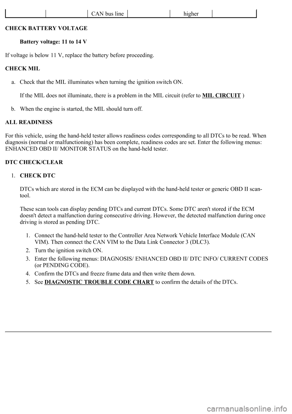
CHECK BATTERY VOLTAGE
Battery voltage: 11 to 14 V
If voltage is below 11 V, replace the battery before proceeding.
CHECK MIL
a. Check that the MIL illuminates when turning the ignition switch ON.
If the MIL does not illuminate, there is a problem in the MIL circuit (refer to MIL CIRCUIT
)
b. When the engine is started, the MIL should turn off.
ALL READINESS
For this vehicle, using the hand-held tester allows readiness codes corresponding to all DTCs to be read. When
diagnosis (normal or malfunctioning) has been complete, readiness codes are set. Enter the following menus:
ENHANCED OBD II/ MONITOR STATUS on the hand-held tester.
DTC CHECK/CLEAR
1.CHECK DTC
DTCs which are stored in the ECM can be displayed with the hand-held tester or generic OBD II scan-
tool.
These scan tools can display pending DTCs and current DTCs. Some DTC aren't stored if the ECM
doesn't detect a malfunction during consecutive driving. However, the detected malfunction during once
driving is stored as pending DTC.
1. Connect the hand-held tester to the Controller Area Network Vehicle Interface Module (CAN
VIM). Then connect the CAN VIM to the Data Link Connector 3 (DLC3).
2. Turn the ignition switch ON.
3. Enter the following menus: DIAGNOSIS/ ENHANCED OBD II/ DTC INFO/ CURRENT CODES
(or PENDING CODE).
4. Confirm the DTCs and freeze frame data and then write them down.
5. See DIAGNOSTIC TROUBLE CODE CHART
to confirm the details of the DTCs.
CAN bus linehigher
Page 2718 of 4500
f. Change the ECM to check mode. Make sure the MIL flashes as shown in the illustration.
g. Start the engine. The MIL should turn off after the engine starts.
h. Perform "MONITOR DRIVE PATTERN" for the ECT test (see MONITOR DRIVE PATTERN
).
(Or, simulate the conditions of the malfunction described by the customer).
i. After simulating the malfunction conditions, use the hand-held tester diagnosis selector to check the DTC
and freeze frame data.
Fig. 39: Identifying MIL Blinking Pattern
Courtesy of TOYOTA MOTOR SALES, U.S.A., INC.
FAIL-SAFE CHART
1.FAIL-SAFE
Page 2743 of 4500

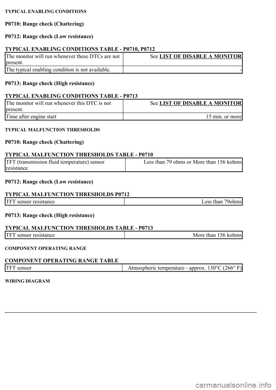
TYPICAL ENABLING CONDITIONS
P0710: Range check (Chattering)
P0712: Range check (Low resistance)
TYPICAL ENABLING CONDITIONS TABLE - P0710, P0712
P0713: Range check (High resistance)
TYPICAL ENABLING CONDITIONS TABLE - P0713
TYPICAL MALFUNCTION THRESHOLDS
P0710: Range check (Chattering)
TYPICAL MALFUNCTION THRESHOLDS TABLE - P0710
P0712: Range check (Low resistance)
TYPICAL MALFUNCTION THRESHOLDS P0712
P0713: Range check (High resistance)
TYPICAL MALFUNCTION THRESHOLDS TABLE - P0713
COMPONENT OPERATING RANGE
COMPONENT OPERATING RANGE TABLE
WIRING DIAGRAM
The monitor will run whenever these DTCs are not
present.See LIST OF DISABLE A MONITOR
The typical enabling condition is not available.-
The monitor will run whenever this DTC is not
present.See LIST OF DISABLE A MONITOR
Time after engine start15 min. or more
TFT (transmission fluid temperature) sensor
resistanceLess than 79 ohms or More than 156 kohms
TFT sensor resistanceLess than 79ohms
TFT sensor resistanceMore than 156 kohms
TFT sensorAtmospheric temperature - approx. 130°C (266° F)
Page 2749 of 4500

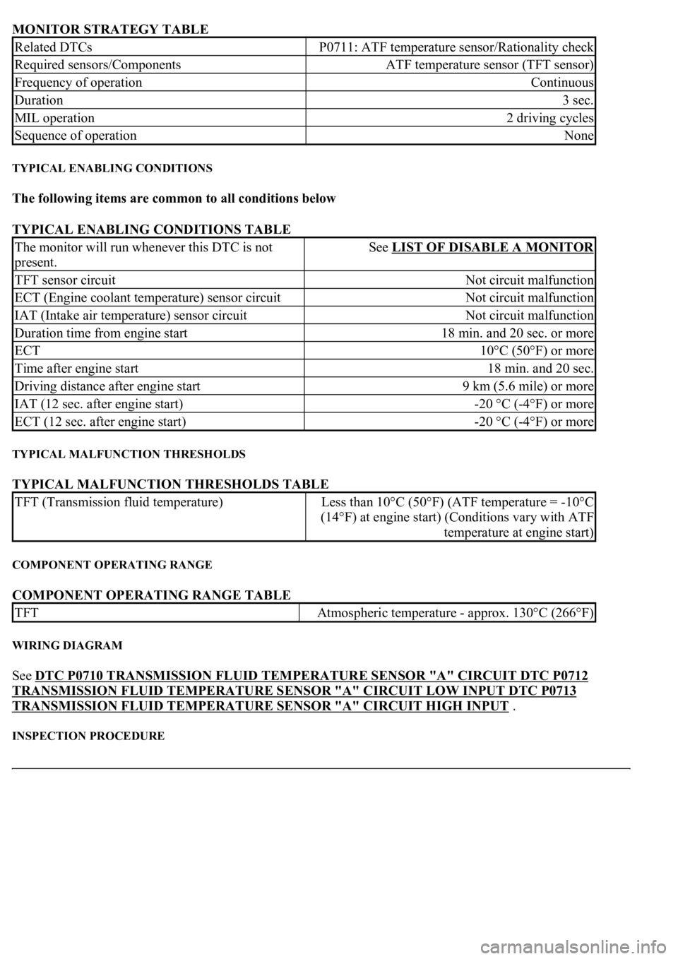
MONITOR STRATEGY TABLE
TYPICAL ENABLING CONDITIONS
The following items are common to all conditions below
TYPICAL ENABLING CONDITIONS TABLE
TYPICAL MALFUNCTION THRESHOLDS
TYPICAL MALFUNCTION THRESHOLDS TABLE
COMPONENT OPERATING RANGE
COMPONENT OPERATING RANGE TABLE
WIRING DIAGRAM
See DTC P0710 TRANSMISSION FLUID TEMPERATURE SENSOR "A" CIRCUIT DTC P0712
TRANSMISSION FLUID TEMPERATURE SENSOR "A" CIRCUIT LOW INPUT DTC P0713
TRANSMISSION FLUID TEMPERATURE SENSOR "A" CIRCUIT HIGH INPUT .
INSPECTION PROCEDURE
Related DTCsP0711: ATF temperature sensor/Rationality check
Required sensors/ComponentsATF temperature sensor (TFT sensor)
Frequency of operationContinuous
Duration3 sec.
MIL operation2 driving cycles
Sequence of operationNone
The monitor will run whenever this DTC is not
present.See LIST OF DISABLE A MONITOR
TFT sensor circuitNot circuit malfunction
ECT (Engine coolant temperature) sensor circuitNot circuit malfunction
IAT (Intake air temperature) sensor circuitNot circuit malfunction
Duration time from engine start18 min. and 20 sec. or more
ECT10°C (50°F) or more
Time after engine start18 min. and 20 sec.
Driving distance after engine start9 km (5.6 mile) or more
IAT (12 sec. after engine start)-20 °C (-4°F) or more
ECT (12 sec. after engine start)-20 °C (-4°F) or more
TFT (Transmission fluid temperature)Less than 10°C (50°F) (ATF temperature = -10°C
(14°F) at engine start) (Conditions vary with ATF
temperature at engine start)
TFTAtmospheric temperature - approx. 130°C (266°F)