Page 1077 of 4500
1.CONNECT HAND-HELD TESTER:
a. Connect the hand-held tester to the DLC3.
b. Start the engine and run at idle.
c. Select the ACTIVE TEST mode on the hand-held tester.
HINT:
Please refer to the hand-held tester operators manual for further details.
Fig. 109: Connecting Hand
-Held Tester To DLC3
Courtesy of TOYOTA MOTOR SALES, U.S.A., INC.
2.INSPECT ACTUATOR MOTOR OPERATION
a. With the motor relay on, check the actuator motor operation noise.
b. Turn the motor relay off.
c. Depress the brake pedal and hold it for approximately 15 seconds. Check that the brake pedal
cannot be depressed.
d. With the motor rela
y on, check that the pedal does not pulsate.
Page 1223 of 4500

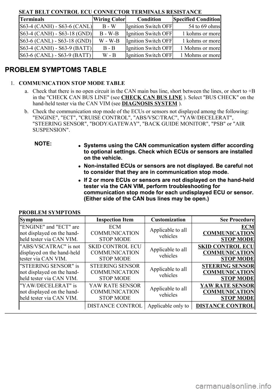
SEAT BELT CONTROL ECU CONNECTOR TERMINALS RESISTANCE
1.COMMUNICATION STOP MODE TABLE
a. Check that there is no open circuit in the CAN main bus line, short between the lines, or short to +B
in the "CHECK CAN BUS LINE" (see CHECK CAN BUS LINE
). Select "BUS CHECK" on the
hand-held tester via the CAN VIM (see DIAGNOSIS SYSTEM
).
b. Check the communication stop mode of the ECUs or sensors not displayed among the following:
"ENGINE", "ECT", "CRUISE CONTROL", "ABS/VSC/TRAC", "YAW/DECELERAT",
"STEERING SENSOR", "BODY/GATEWAY", "BACK GUIDE MONITOR", "PSB" or "AIR
SUSPENSION".
PROBLEM SYMPTOMS
TerminalsWiring ColorConditionSpecified Condition
S63-4 (CANH) - S63-6 (CANL)B - WIgnition Switch OFF54 to 69 ohms
S63-4 (CANH) - S63-18 (GND)B - W-BIgnition Switch OFF1 kohms or more
S63-6 (CANL) - S63-18 (GND)W - W-BIgnition Switch OFF1 kohms or more
S63-4 (CANH) - S63-9 (BATT)B - BIgnition Switch OFF1 Mohms or more
S63-6 (CANL) - S63-9 (BATT)W - BIgnition Switch OFF1 Mohms or more
SymptomInspection ItemCustomizationSee Procedure
"ENGINE" and "ECT" are
not displayed on the hand-
held tester via CAN VIM.ECM
COMMUNICATION
STOP MODEApplicable to all
vehiclesECM
COMMUNICATION
STOP MODE
"ABS/VSCATRAC" is not
displayed on the hand-held
tester via CAN VIM.SKID CONTROL ECU
COMMUNICATION
STOP MODEApplicable to all
vehiclesSKID CONTROL ECU
COMMUNICATION
STOP MODE
"STEERING SENSOR" is
not displayed on the hand-
held tester via CAN VIM.STEERING SENSOR
COMMUNICATION
STOP MODEApplicable to all
vehiclesSTEERING SENSOR
COMMUNICATION
STOP MODE
"YAW/DECELERAT" is
not displayed on the hand-
held tester via CAN VIM.YAW RATE SENSOR
COMMUNICATION
STOP MODEApplicable to all
vehiclesYAW RATE SENSOR
COMMUNICATION
STOP MODE
DISTANCE CONTROL Applicable only to DISTANCE CONTROL
Page 1503 of 4500

a. This system uses ultrasonic sensors to detect any obstacles at the corners, the front or the rear of the
vehicle. The system then informs the driver of the distance between the sensors and the obstacles,
as well as their positions by displaying them on the multi-information display in the combination
meter and by sounding a buzzer. This information also appears on the multi-display on the models
equipped with a LEXUS navigation system.
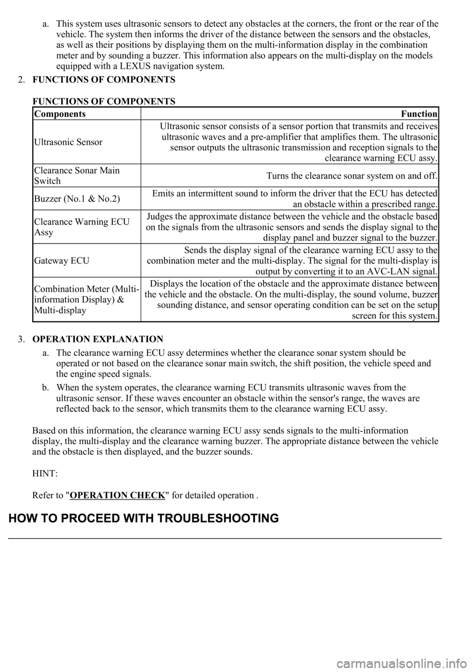
2.FUNCTIONS OF COMPONENTS
FUNCTIONS OF COMPONENTS
3.OPERATION EXPLANATION
a. The clearance warning ECU assy determines whether the clearance sonar system should be
operated or not based on the clearance sonar main switch, the shift position, the vehicle speed and
the engine speed signals.
b. When the system operates, the clearance warning ECU transmits ultrasonic waves from the
ultrasonic sensor. If these waves encounter an obstacle within the sensor's range, the waves are
reflected back to the sensor, which transmits them to the clearance warning ECU assy.
Based on this information, the clearance warning ECU assy sends signals to the multi-information
display, the multi-display and the clearance warning buzzer. The appropriate distance between the vehicle
and the obstacle is then displayed, and the buzzer sounds.
HINT:
Refer to "OPERATION CHECK
" for detailed operation .
ComponentsFunction
Ultrasonic Sensor
Ultrasonic sensor consists of a sensor portion that transmits and receives
ultrasonic waves and a pre-amplifier that amplifies them. The ultrasonic
sensor outputs the ultrasonic transmission and reception signals to the
clearance warning ECU assy.
Clearance Sonar Main
SwitchTurns the clearance sonar system on and off.
Buzzer (No.1 & No.2)Emits an intermittent sound to inform the driver that the ECU has detected
an obstacle within a prescribed range.
Clearance Warning ECU
AssyJudges the approximate distance between the vehicle and the obstacle based
on the signals from the ultrasonic sensors and sends the display signal to the
display panel and buzzer signal to the buzzer.
Gateway ECU
Sends the display signal of the clearance warning ECU assy to the
combination meter and the multi-display. The signal for the multi-display is
output by converting it to an AVC-LAN signal.
Combination Meter (Multi-
information Display) &
Multi-displayDisplays the location of the obstacle and the approximate distance between
the vehicle and the obstacle. On the multi-display, the sound volume, buzzer
sounding distance, and sensor operating condition can be set on the setup
screen for this system.
Page 1514 of 4500
Fig. 8: Identifying Clearance Sonar Display
Courtesy of TOYOTA MOTOR SALES, U.S.A., INC.
2.INITIAL CHECK FUNCTION CHECK
a. Turn the ignition switch to the ON position.
b. Drive the engine at 2,500 RPM or less with the shift lever in any position except N, or at 1,500
RPM or less with the shift lever in the N position.
Page 1762 of 4500
Fig. 26: Identifying Terminals Of ECU (Combination Meter Assy)
Courtesy of TOYOTA MOTOR SALES, U.S.A., INC.
COMBINATION METER ASSY CONNECTOR TERMINALS REFERENCE
Symbols
(Terminals No.)Wiring
ColorTerminal DescriptionConditionSpecified
Condition
IG + (C12-1) -
Body groundY - Body
groundIgnition switch signal
(ON)Ignition switch OFF -->
ONBelow 1 V --> 10
to 14 V
MPX + (C12-2) -
Body groundGR-B -
Body groundMultiplex
communication signal--
MPX- (C12-3) -
Body groundGR-B -
Body groundMultiplex
communication signal--
S (C12-4) - Body
groundB-Y - Body
groundTachometer signalEngine runningPulse generation
(See waveform 1)
CHECK (C12-5) -
Body groundY-R - Body
groundCHECK ENGINE
signalCHECK ENGINE warning
light ON --> OFFBelow 1 V --> 10
to 14 V
TEMS (C12-6) -
Body groundY - Body
groundTEMS SPORT signalTEMS SPORT indicator
light ON --> OFFBelow 1 V --> 10
to 14 V
A/B (C12-7) - V-R (W) - ODO/TRIP signalIgnition switch ON,
ODO/TRIP switch ON -->
Below 1 V --> 4.5
Page 1781 of 4500

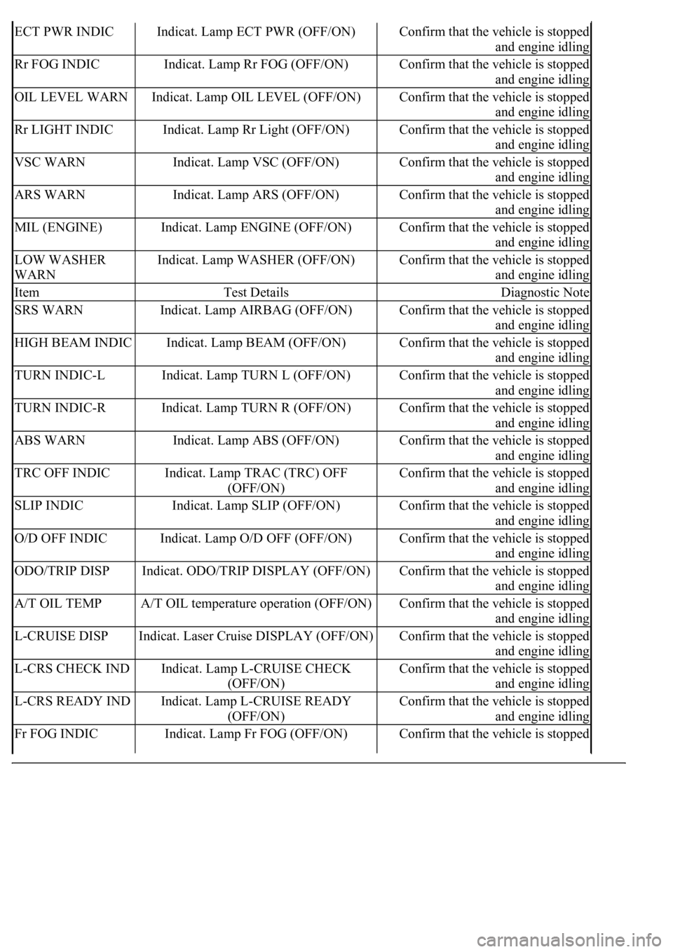
ECT PWR INDICIndicat. Lamp ECT PWR (OFF/ON)Confirm that the vehicle is stopped
and engine idling
Rr FOG INDICIndicat. Lamp Rr FOG (OFF/ON)Confirm that the vehicle is stopped
and engine idling
OIL LEVEL WARNIndicat. Lamp OIL LEVEL (OFF/ON)Confirm that the vehicle is stopped
and engine idling
Rr LIGHT INDICIndicat. Lamp Rr Light (OFF/ON)Confirm that the vehicle is stopped
and engine idling
VSC WARNIndicat. Lamp VSC (OFF/ON)Confirm that the vehicle is stopped
and engine idling
ARS WARNIndicat. Lamp ARS (OFF/ON)Confirm that the vehicle is stopped
and engine idling
MIL (ENGINE)Indicat. Lamp ENGINE (OFF/ON)Confirm that the vehicle is stopped
and engine idling
LOW WASHER
WARNIndicat. Lamp WASHER (OFF/ON)Confirm that the vehicle is stopped
and engine idling
ItemTest DetailsDiagnostic Note
SRS WARNIndicat. Lamp AIRBAG (OFF/ON)Confirm that the vehicle is stopped
and engine idling
HIGH BEAM INDICIndicat. Lamp BEAM (OFF/ON)Confirm that the vehicle is stopped
and engine idling
TURN INDIC-LIndicat. Lamp TURN L (OFF/ON)Confirm that the vehicle is stopped
and engine idling
TURN INDIC-RIndicat. Lamp TURN R (OFF/ON)Confirm that the vehicle is stopped
and engine idling
ABS WARNIndicat. Lamp ABS (OFF/ON)Confirm that the vehicle is stopped
and engine idling
TRC OFF INDICIndicat. Lamp TRAC (TRC) OFF
(OFF/ON)Confirm that the vehicle is stopped
and engine idling
SLIP INDICIndicat. Lamp SLIP (OFF/ON)Confirm that the vehicle is stopped
and engine idling
O/D OFF INDICIndicat. Lamp O/D OFF (OFF/ON)Confirm that the vehicle is stopped
and engine idling
ODO/TRIP DISPIndicat. ODO/TRIP DISPLAY (OFF/ON)Confirm that the vehicle is stopped
and engine idling
A/T OIL TEMPA/T OIL temperature operation (OFF/ON)Confirm that the vehicle is stopped
and engine idling
L-CRUISE DISPIndicat. Laser Cruise DISPLAY (OFF/ON)Confirm that the vehicle is stopped
and engine idling
L-CRS CHECK INDIndicat. Lamp L-CRUISE CHECK
(OFF/ON)Confirm that the vehicle is stopped
and engine idling
L-CRS READY INDIndicat. Lamp L-CRUISE READY
(OFF/ON)Confirm that the vehicle is stopped
and engine idling
Fr FOG INDICIndicat. Lamp Fr FOG (OFF/ON)Confirm that the vehicle is stopped
Page 1793 of 4500

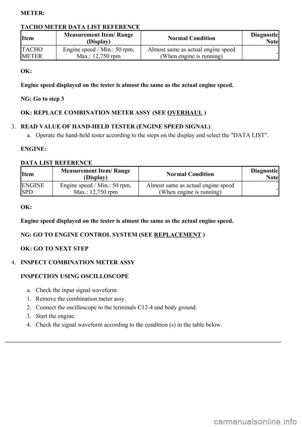
METER:
TACHO METER DATA LIST REFERENCE
OK:
Engine speed displayed on the tester is almost the same as the actual engine speed.
NG: Go to step 3
OK: REPLACE COMBINATION METER ASSY (SEE OVERHAUL
)
3.READ VALUE OF HAND-HELD TESTER (ENGINE SPEED SIGNAL)
a. Operate the hand-held tester according to the steps on the display and select the "DATA LIST".
ENGINE:
DATA LIST REFERENCE
OK:
Engine speed displayed on the tester is almost the same as the actual engine speed.
NG: GO TO ENGINE CONTROL SYSTEM (SEE REPLACEMENT
)
OK: GO TO NEXT STEP
4.INSPECT COMBINATION METER ASSY
INSPECTION USING OSCILLOSCOPE
a. Check the input signal waveform.
1. Remove the combination meter assy.
2. Connect the oscilloscope to the terminals C12-4 and body ground.
3. Start the engine.
4. Check the si
gnal waveform according to the condition (s) in the table below.
ItemMeasurement Item/ Range
(Display)Normal ConditionDiagnostic
Note
TACHO
METEREngine speed / Min.: 50 rpm,
Max.: 12,750 rpmAlmost same as actual engine speed
(When engine is running)-
ItemMeasurement Item/ Range
(Display)Normal ConditionDiagnostic
Note
ENGINE
SPDEngine speed / Min.: 50 rpm,
Max.: 12,750 rpmAlmost same as actual engine speed
(When engine is running)-
Page 1843 of 4500
c. Check the deflection width of the speedometer indicator.
Reference: Below 0.5 km/h (0.3 mph)
2.INSPECT OUTPUT OF VEHICLE SPEED
a. Check the output signal waveform.
1. Remove the combination meter assy.
2. Connect the oscilloscope to terminal C12-19 and body ground.
3. Start the engine.
Fig. 87: Identifying Terminal C12
-19
Courtesy of TOYOTA MOTOR SALES, U.S.A., INC.
4. Check the signal waveform according to the condition (s) in the table below.
SIGNAL WAVEFORM CONDITIONS
ItemCondition
Tool setting5 V/DIV, 20 ms/DIV