Page 735 of 4500
![LEXUS LS430 2003 Factory Repair Manual Fig. 28: DTC Detecting Condition Chart (Physical address: 17D) [TEL])
Courtesy of TOYOTA MOTOR SALES, U.S.A., INC.
HINT:
*1: Even if no failure is detected, a trouble code may be recorded depending LEXUS LS430 2003 Factory Repair Manual Fig. 28: DTC Detecting Condition Chart (Physical address: 17D) [TEL])
Courtesy of TOYOTA MOTOR SALES, U.S.A., INC.
HINT:
*1: Even if no failure is detected, a trouble code may be recorded depending](/manual-img/36/57050/w960_57050-734.png)
Fig. 28: DTC Detecting Condition Chart (Physical address: 17D) [TEL])
Courtesy of TOYOTA MOTOR SALES, U.S.A., INC.
HINT:
*1: Even if no failure is detected, a trouble code may be recorded depending on the battery
condition or engine start voltage.
*2: If the power connector is disconnected after the engine starts, this code is recorded after
180 seconds.
*3: This code may be stored if the ignition key is turned again after the engine starts.
*4: This code may be stored if the ignition key is held in the START position for one minute
or more before returning to the ON position.
*5: If the device is reported as not existing during verification, check the power source circuit
and AVC-LAN circuit for the device.
b. Logical address: 57 (telephone information drawing): 68 (TEL)
HINT:
Methods used to verify the cause of the problem are listed in order of probability in the verification
column.
Fig. 29: DTC Detecting Condition Chart
Courtesy of TOYOTA MOTOR SALES, U.S.A., INC.
3.AUDIO AND REAR A/C CONTROL SW (Physical address: 1CO) [Rr-CONT]
a. Logical address: 01 (Communication control)
HINT:
Methods used to verify the cause of the problem are listed in order of probability in the verification
column.
Page 737 of 4500

Fig. 30: DTC Detecting Condition Chart (Audio And Rear A/C Control SW)
Courtesy of TOYOTA MOTOR SALES, U.S.A., INC.
HINT:
*1: Even if no failure is detected, a trouble code may be recorded depending on the battery
condition or engine start voltage.
*2: If the power connector is disconnected after the engine starts, this code is recorded after
180 seconds.
*3: This code may be stored if the ignition key is turned again after the engine starts.
*4: This code may be stored if the ignition key is held in the START position for one minute
or more before returning to the ON position.
*5: If the device is reported as not existing during verification, check the power source circuit
and AVC-LAN circuit for the device.
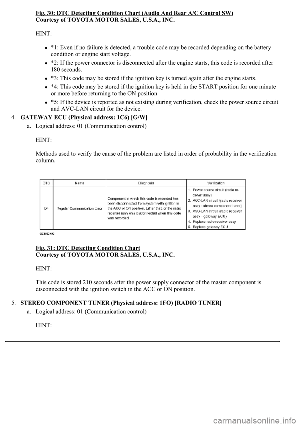
4.GATEWAY ECU (Physical address: 1C6) [G/W]
a. Logical address: 01 (Communication control)
HINT:
Methods used to verify the cause of the problem are listed in order of probability in the verification
column.
Fig. 31: DTC Detecting Condition Chart
Courtesy of TOYOTA MOTOR SALES, U.S.A., INC.
HINT:
This code is stored 210 seconds after the power supply connector of the master component is
disconnected with the ignition switch in the ACC or ON position.
5.STEREO COMPONENT TUNER (Physical address: 1FO) [RADIO TUNER]
a. Logical address: 01 (Communication control)
HINT:
Page 739 of 4500
HINT:
*1: Even if no failure is detected, a trouble code may be recorded depending on the battery
condition or engine start voltage.
*2: If the power connector is disconnected after the engine starts, this code is recorded after
180 seconds.
*3: This code may be stored if the ignition key is turned again after the engine starts.
*4: This code may be stored if the ignition key is held in the START position for one minute
or more before returning to the ON position.
*5: If the device is reported as not existing during verification, check the power source circuit
and AVC-LAN circuit for the device.
b. Logical address: 60 (Radio)
HINT:
Methods used to verify the cause of the problem are listed in order of probability in the verification
column.
Fig. 33: DTC Detecting Condition Chart
Courtesy of TOYOTA MOTOR SALES, U.S.A., INC.
Page 742 of 4500

Fig. 34: DTC Detecting Condition Chart Physical (Address: 440)
Courtesy of TOYOTA MOTOR SALES, U.S.A., INC.
HINT:
*1: Even if no failure is detected, a trouble code may be recorded depending on the battery
condition or engine start voltage.
*2: If the power connector is disconnected after the engine starts, this code is recorded after
180 seconds.
*3: This code may be stored if the ignition key is turned again after the engine starts.
*4: This code may be stored if the ignition key is held in the START position for one minute
or more before returning to the ON position.
*5: If the device is reported as not existing during verification, check the power source circuit
and AVC-LAN circuit for the device.
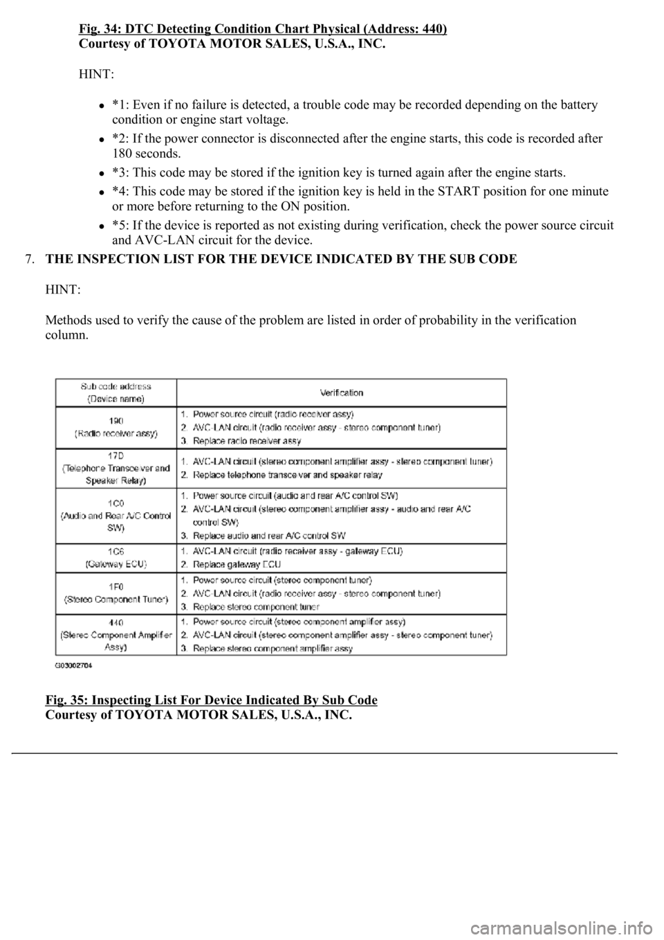
7.THE INSPECTION LIST FOR THE DEVICE INDICATED BY THE SUB CODE
HINT:
Methods used to verify the cause of the problem are listed in order of probability in the verification
column.
Fig. 35: Inspecting List For Device Indicated By Sub Code
Courtesy of TOYOTA MOTOR SALES, U.S.A., INC.
Page 749 of 4500

NG: REPLACE THE CD
OK: Go to next step
3.CHECK RADIO RECEIVER ASSY
a. Insert another CD and check if it is ejected.
OK: The disc is ejected.
NG: REPLACE RADIO RECEIVER ASSY (SEE REPLACEMENT
)
OK: NORMAL OPERATION
INSPECTION PROCEDURE
1.CHECK SPEAKERS
a. Check the speaker unit installed condition.
1. Check that each speaker is securely installed.
OK: The problem goes away.
HINT:
The radio has a noise prevention function to reduce noise when listening to the radio. If a loud noise
occurs, check whether the ground at the antenna mounting base and the noise prevention unit are installed
and wired correctly.
NOISE CONDITION CHART
Noise ConditionsNoise Source
Depressing the accelerator pedal makes the noise louder. However, the noise
stops immediately when the engine is stopped.Alternator
Noise occurs while the A/C or heater is in operation.Blower motor
Noise can be heard during sudden acceleration on an unpaved road, or after the
ignition switch is turned ON.Fuel pump
Noise can be heard when the horn is pressed and released, or held down
continuously.Horn
<00340058004c00480057000300510052004c0056004800030046004400510003004500480003004b00480044005500470003005a004b004c004f004800030057004b0048000300480051004a004c0051004800030055005800510056000f00030045005800
570003005600570052005300560003005a004b004800510003[the engine is
stopped.Ignition
Noise can be heard when the turn signal blinks.Flasher
Noise can be heard while window washer is in operation.Washer
Noise can be heard while the engine is running and continues after it is stopped.Water temperature
sensor
Noise can be heard while the wiper system is in operation.Wiper
Page 822 of 4500
HINT:
If you cannot add the listed amount of fluid, do the following:
1. Install the refill plug.
2. Allow the engine to idle with air conditioning OFF.
3. Move the shift lever through entire gear range to circulate fluid.
4. Wait for 30 seconds with the engine idling.
5. Stop the engine.
6. Remove the refill plug and add fluid.
7. Reinstall the refill plug.
4.FLUID CIRCULATION
a. Allow the engine to idle with the air conditioning OFF.
b. Move the shift lever through entire gear range to circulate fluid.
5.FLUID TEMPERATURE CHECK
a. With hand-held tester
1. Connect the han
d-held tester to the DLC3.
Output shaft oil seal replacement0.4 liters (0.42 US qts, 0.35 Imp. qts)
Transmission pan and drain plug removal1.3 liters (1.37 US qts, 1.14 Imp. qts)
Transmission valve body removal3.9 liters (4.12 US qts, 3.43 Imp. qts)
Torque converter replacement5.3 liters (5.60 US qts, 4.66 Imp. qts)
Entire transmission assembly7.2 liters (7.61 US qts, 6.34 Imp. qts)
Page 823 of 4500

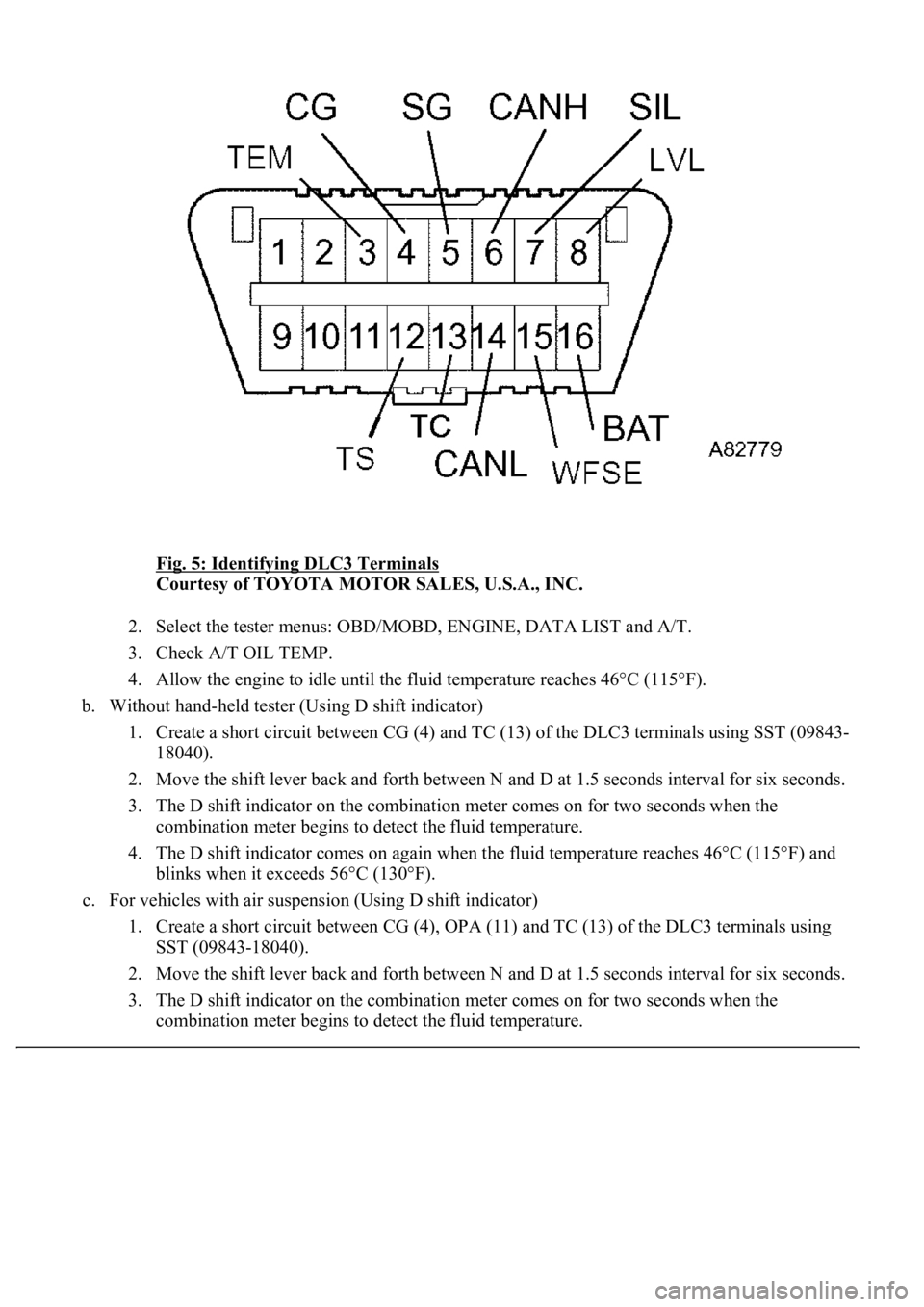
Fig. 5: Identifying DLC3 Terminals
Courtesy of TOYOTA MOTOR SALES, U.S.A., INC.
2. Select the tester menus: OBD/MOBD, ENGINE, DATA LIST and A/T.
3. Check A/T OIL TEMP.
4. Allow the engine to idle until the fluid temperature reaches 46°C (115°F).
b. Without hand-held tester (Using D shift indicator)
1. Create a short circuit between CG (4) and TC (13) of the DLC3 terminals using SST (09843-
18040).
2. Move the shift lever back and forth between N and D at 1.5 seconds interval for six seconds.
3. The D shift indicator on the combination meter comes on for two seconds when the
combination meter begins to detect the fluid temperature.
4. The D shift indicator comes on again when the fluid temperature reaches 46°C (115°F) and
blinks when it exceeds 56°C (130°F).
c. For vehicles with air suspension (Using D shift indicator)
1. Create a short circuit between CG (4), OPA (11) and TC (13) of the DLC3 terminals using
SST (09843-18040).
2. Move the shift lever back and forth between N and D at 1.5 seconds interval for six seconds.
3. The D shift indicator on the combination meter comes on for two seconds when the
combination meter begins to detect the fluid temperature.
Page 824 of 4500
4. The D shift indicator comes on again when the fluid temperature reaches 46°C (115°F) and
blinks when it exceeds 56°C (130°F).
5. Allow the engine to idle until the fluid temperature reaches 46°C (115°F).
HINT:
The fluid temperature should be less than 30°C (86°F) before check the fluid temperature.
6.FLUID LEVEL CHECK
a. Remove the overflow plug with the engine idling.
b. Check that the fluid comes out of the overflow tube.
If fluid does not come out, proceed to step 7
If fluid comes out, wait until the over-flow slows to a trickle and proceed to step 8.
Fig. 6: Removing Overflow Plug
Courtesy of TOYOTA MOTOR SALES, U.S.A., INC.