Page 1881 of 4500

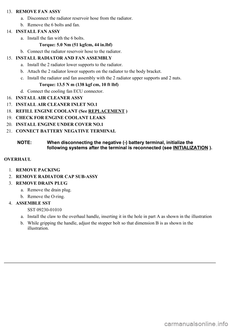
13.REMOVE FAN ASSY
a. Disconnect the radiator reservoir hose from the radiator.
b. Remove the 6 bolts and fan.
14.INSTALL FAN ASSY
a. Install the fan with the 6 bolts.
Torque: 5.0 Nm (51 kgfcm, 44 in.lbf)
b. Connect the radiator reservoir hose to the radiator.
15.INSTALL RADIATOR AND FAN ASSEMBLY
a. Install the 2 radiator lower supports to the radiator.
b. Attach the 2 radiator lower supports on the radiator to the body bracket.
c. Install the radiator and fan assembly with the 2 radiator upper supports and 2 nuts.
Torque: 13.5 N m (138 kgf cm, 10 ft lbf)
d. Connect the cooling fan ECU connector.
16.INSTALL AIR CLEANER ASSY
17.INSTALL AIR CLEANER INLET NO.1
18.REFILL ENGINE COOLANT (See REPLACEMENT
)
19.CHECK FOR ENGINE COOLANT LEAKS
20.INSTALL ENGINE UNDER COVER NO.1
21.CONNECT BATTERY NEGATIVE TERMINAL
OVERHAUL
1.REMOVE PACKING
2.REMOVE RADIATOR CAP SUB-ASSY
3.REMOVE DRAIN PLUG
a. Remove the drain plug.
b. Remove the O-ring.
4.ASSEMBLE SST
SST 09230-01010
a. Install the claw to the overhaul handle, inserting it in the hole in part A as shown in the illustration
b. While gripping the handle, adjust the stopper bolt so that dimension B is as shown in the
illustration.
Page 1948 of 4500
3. With the brake pedal depressed, push the cruise control main switch to RES/ACC 3 times within 3
seconds. Check that the VSC buzzer sounds at this time.
REPLACEMENT
1.SEPARATE BATTERY NEGATIVE TERMINAL
2.REMOVE ENGINE UNDER COVER NO. 1 (See REPLACEMENT
)
3.REMOVE FRONT WHEEL OPENING EXTENSION PAD LH (See REPLACEMENT
)
4.REMOVE FRONT FENDER LINER LH (See REPLACEMENT
)
5.REMOVE FRONT WHEEL OPENING EXTENSION PAD RH (See REPLACEMENT
)
6.REMOVE FRONT FENDER LINER RH (See REPLACEMENT
)
7.REMOVE FRONT BUMPER COVER (See step 5 in REPLACEMENT
)
8.REMOVE FRONT BUMPER REINFORCEMENT SUB-ASSY (See step 9 in REPLACEMENT
)
9.REMOVE LASER SENSOR
a. Disconnect the connector and remove the laser sensor.
Page 2000 of 4500

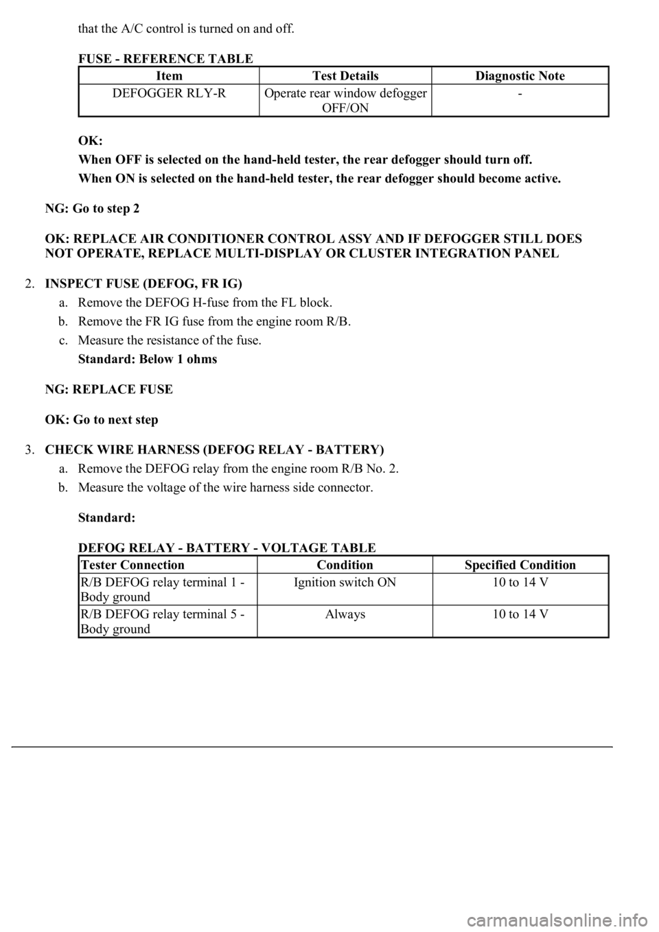
that the A/C control is turned on and off.
FUSE - REFERENCE TABLE
OK:
When OFF is selected on the hand-held tester, the rear defogger should turn off.
When ON is selected on the hand-held tester, the rear defogger should become active.
NG: Go to step 2
OK: REPLACE AIR CONDITIONER CONTROL ASSY AND IF DEFOGGER STILL DOES
NOT OPERATE, REPLACE MULTI-DISPLAY OR CLUSTER INTEGRATION PANEL
2.INSPECT FUSE (DEFOG, FR IG)
a. Remove the DEFOG H-fuse from the FL block.
b. Remove the FR IG fuse from the engine room R/B.
c. Measure the resistance of the fuse.
Standard: Below 1 ohms
NG: REPLACE FUSE
OK: Go to next step
3.CHECK WIRE HARNESS (DEFOG RELAY - BATTERY)
a. Remove the DEFOG relay from the engine room R/B No. 2.
b. Measure the voltage of the wire harness side connector.
Standard:
DEFOG RELAY - BATTERY - VOLTAGE TABLE
ItemTest DetailsDiagnostic Note
DEFOGGER RLY-ROperate rear window defogger
OFF/ON-
Tester ConnectionConditionSpecified Condition
R/B DEFOG relay terminal 1 -
Body groundIgnition switch ON10 to 14 V
R/B DEFOG relay terminal 5 -
Body groundAlways10 to 14 V
Page 2001 of 4500
Fig. 9: Checking Wire Harness (Defog Relay - Battery)
Courtesy of TOYOTA MOTOR SALES, U.S.A., INC.
NG: REPAIR OR REPLACE HARNESS AND CONNECTOR
OK: Go to next step
4.INSPECT RELAY (Marking: DEFOG)
a. Remove the DEFOG relay from the engine room R/B No. 2.
b. Measure the resistance of the relay.
Standard:
RELAY (Marking: DEFOG) - RESISTANCE TABLE
Tester ConnectionSpecified Condition
3-4Below 1 ohms
3-510 kohms or higher
3-5Below 1 ohms (when battery voltage is applied
to terminals 1 and 2)
Page 2002 of 4500
Fig. 10: Inspecting Relay
Courtesy of TOYOTA MOTOR SALES, U.S.A., INC.
NG: REPLACE RELAY
OK: Go to next step
5.CHECK WIRE HARNESS (REAR WINDOW DEFOGGER - DEFOG RELAY AND BODY
GROUND)
a. Disconnect the R22 and R23 defogger connectors.
b. Disconnect the DEFOG relay from the engine room R/B No. 2.
c. Measure the resistance of the wire harness side connectors.
Standard:
REAR WINDOW DEFOGGER - DEFOG RELAY AND BODY GROUND - RESISTANCE
TABLE
Tester ConnectionSpecified Condition
R22-1 - R/B DEFOG relay terminal 3Below 1 ohms
R23-1 - Body groundBelow 1 ohms
Page 2004 of 4500
OK: Go to next step
6.CHECK WIRE HARNESS (DEFOG RELAY - A/C CONTROL ASSY)
a. Remove the DEFOG relay from the engine room R/B No. 2.
b. Disconnect the A11 A/C control connector.
c. Measure the resistance of the wire harness side connector.
Standard:
DEFOG RELAY - A/C CONTROL ASSY - RESISTANCE TABLE
Tester ConnectionSpecified Connection
A11-8 (RDFGR) - R/B DEFOG relay terminal 2Below 1 ohms
Page 2025 of 4500

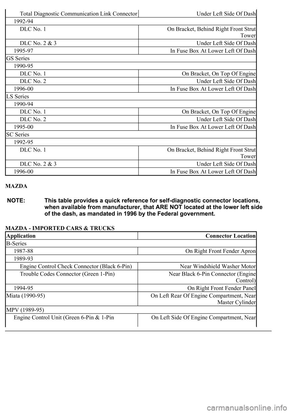
MAZDA
MAZDA - IMPORTED CARS & TRUCKS
Total Diagnostic Communication Link ConnectorUnder Left Side Of Dash
1992-94
DLC No. 1On Bracket, Behind Right Front Strut
Tower
DLC No. 2 & 3Under Left Side Of Dash
1995-97In Fuse Box At Lower Left Of Dash
GS Series
1990-95
DLC No. 1On Bracket, On Top Of Engine
DLC No. 2Under Left Side Of Dash
1996-00In Fuse Box At Lower Left Of Dash
LS Series
1990-94
DLC No. 1On Bracket, On Top Of Engine
DLC No. 2Under Left Side Of Dash
1995-00In Fuse Box At Lower Left Of Dash
SC Series
1992-95
DLC No. 1On Bracket, Behind Right Front Strut
Tower
DLC No. 2 & 3Under Left Side Of Dash
1996-00In Fuse Box At Lower Left Of Dash
ApplicationConnector Location
B-Series
1987-88On Right Front Fender Apron
1989-93
Engine Control Check Connector (Black 6-Pin)Near Windshield Washer Motor
Trouble Codes Connector (Green 1-Pin)Near Black 6-Pin Connector (Engine
Control)
1994-95On Right Front Fender Panel
Miata (1990-95)On Left Rear Of Engine Compartment, Near
Master Cylinder
MPV (1989-95)
Engine Control Unit (Green 6-Pin & 1-Pin On Left Side Of Engine Compartment, Near
Page 2026 of 4500

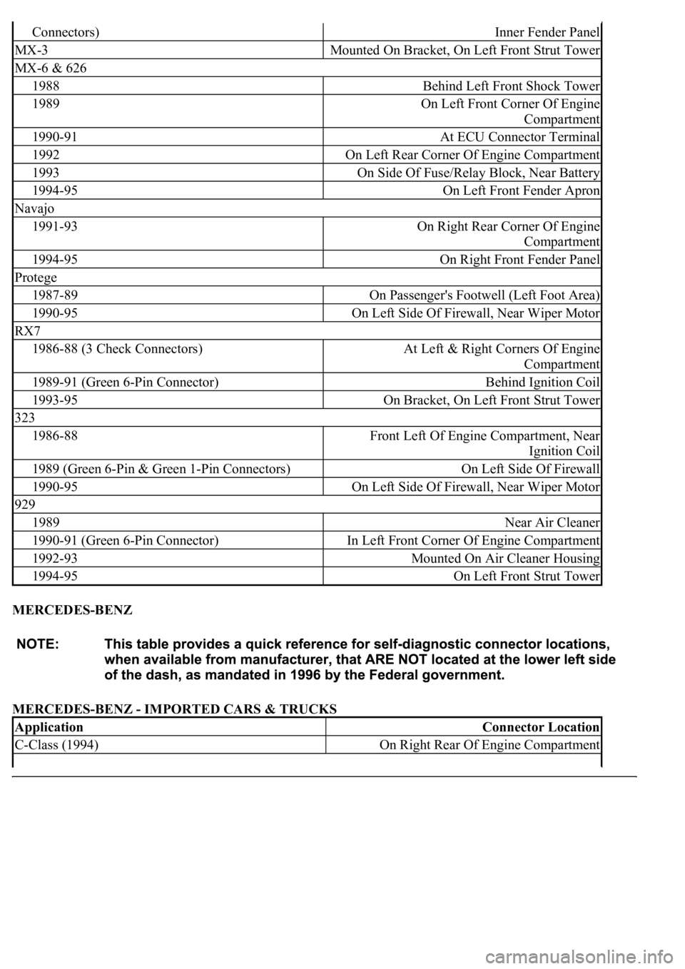
MERCEDES-BENZ
MERCEDES-BENZ - IMPORTED CARS & TRUCKS
Connectors)Inner Fender Panel
MX-3Mounted On Bracket, On Left Front Strut Tower
MX-6 & 626
1988Behind Left Front Shock Tower
1989On Left Front Corner Of Engine
Compartment
1990-91At ECU Connector Terminal
1992On Left Rear Corner Of Engine Compartment
1993On Side Of Fuse/Relay Block, Near Battery
1994-95On Left Front Fender Apron
Navajo
1991-93On Right Rear Corner Of Engine
Compartment
1994-95On Right Front Fender Panel
Protege
1987-89On Passenger's Footwell (Left Foot Area)
1990-95On Left Side Of Firewall, Near Wiper Motor
RX7
1986-88 (3 Check Connectors)At Left & Right Corners Of Engine
Compartment
1989-91 (Green 6-Pin Connector)Behind Ignition Coil
1993-95On Bracket, On Left Front Strut Tower
323
1986-88Front Left Of Engine Compartment, Near
Ignition Coil
1989 (Green 6-Pin & Green 1-Pin Connectors)On Left Side Of Firewall
1990-95On Left Side Of Firewall, Near Wiper Motor
929
1989Near Air Cleaner
1990-91 (Green 6-Pin Connector)In Left Front Corner Of Engine Compartment
1992-93Mounted On Air Cleaner Housing
1994-95On Left Front Strut Tower
ApplicationConnector Location
C-Class (1994)On Right Rear Of Engine Compartment